Page 107 of 3924

AT-34
< SERVICE INFORMATION >
A/T CONTROL SYSTEM
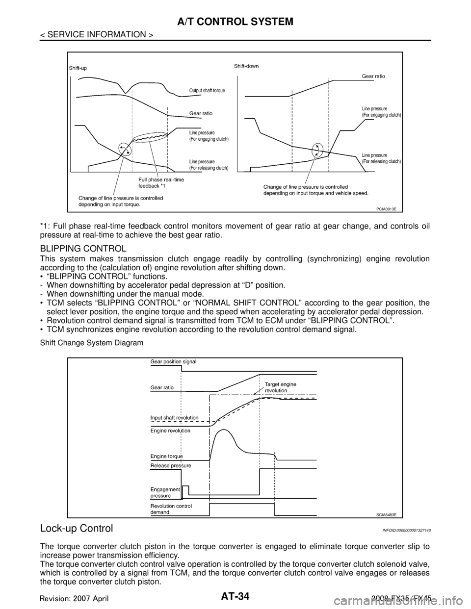
*1: Full phase real-time feedback control monitors movement of gear ratio at gear change, and controls oil
pressure at real-time to achieve the best gear ratio.
BLIPPING CONTROL
This system makes transmission clutch engage readily by controlling (synchronizing) engine revolution
according to the (calculation of) engine revolution after shifting down.
“BLIPPING CONTROL” functions.
- When downshifting by accelerator pedal depression at “D” position.
- When downshifting under the manual mode.
TCM selects “BLIPPING CONTROL” or “NORMAL SHIFT CONTROL” according to the gear position, the
select lever position, the engine torque and the speed when accelerating by accelerator pedal depression.
Revolution control demand signal is transmitted from TCM to ECM under “BLIPPING CONTROL”.
TCM synchronizes engine revolution according to the revolution control demand signal.
Shift Change System Diagram
Lock-up ControlINFOID:0000000001327140
The torque converter clutch piston in the torque conv erter is engaged to eliminate torque converter slip to
increase power transmission efficiency.
The torque converter clutch control valve operation is c ontrolled by the torque converter clutch solenoid valve,
which is controlled by a signal from TCM, and the to rque converter clutch control valve engages or releases
the torque converter clutch piston.
PCIA0013E
SCIA6483E
3AA93ABC3ACD3AC03ACA3AC03AC63AC53A913A773A893A873A873A8E3A773A983AC73AC93AC03AC3
3A893A873A873A8F3A773A9D3AAF3A8A3A8C3A863A9D3AAF3A8B3A8C
Page 108 of 3924

A/T CONTROL SYSTEMAT-35
< SERVICE INFORMATION >
DE
F
G H
I
J
K L
M A
B
AT
N
O P
Lock-up Operation Condition Table
TORQUE CONVERTER CLUTCH CONTROL VALVE CONTROL
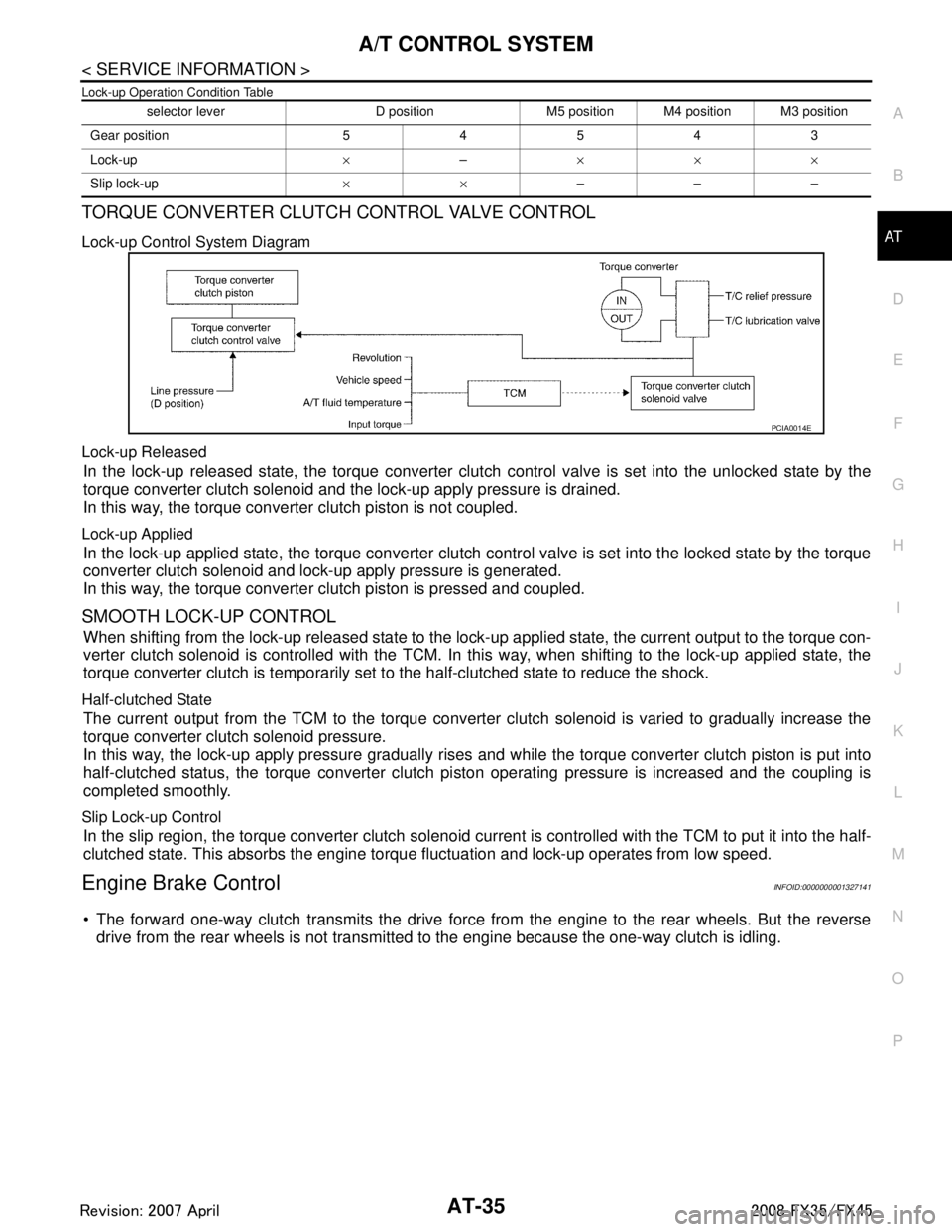
Lock-up Control System Diagram
Lock-up Released
In the lock-up released state, the torque converter clutch control valve is set into the unlocked state by the
torque converter clutch solenoid and the lock-up apply pressure is drained.
In this way, the torque converter clutch piston is not coupled.
Lock-up Applied
In the lock-up applied state, the torque converter clutch control valve is set into the locked state by the torque
converter clutch solenoid and lock-up apply pressure is generated.
In this way, the torque converter clutch piston is pressed and coupled.
SMOOTH LOCK-UP CONTROL
When shifting from the lock-up released state to the lock- up applied state, the current output to the torque con-
verter clutch solenoid is controlled with the TCM. In this way, when shifting to the lock-up applied state, the
torque converter clutch is temporarily set to the half-clutched state to reduce the shock.
Half-clutched State
The current output from the TCM to the torque converte r clutch solenoid is varied to gradually increase the
torque converter clutch solenoid pressure.
In this way, the lock-up apply pressure gradually rises and while the torque converter clutch piston is put into
half-clutched status, the torque converter clutch pi ston operating pressure is increased and the coupling is
completed smoothly.
Slip Lock-up Control
In the slip region, the torque converter clutch solenoid cu rrent is controlled with the TCM to put it into the half-
clutched state. This absorbs the engine torque fluctuation and lock-up operates from low speed.
Engine Brake ControlINFOID:0000000001327141
The forward one-way clutch transmits the drive force from the engine to the rear wheels. But the reverse
drive from the rear wheels is not transmitted to the engine because the one-way clutch is idling.
selector lever D position M5 position M4 position M3 position
Gear position 54543
Lock-up ×– ×××
Slip lock-up ××–––
PCIA0014E
3AA93ABC3ACD3AC03ACA3AC03AC63AC53A913A773A893A873A873A8E3A773A983AC73AC93AC03AC3
3A893A873A873A8F3A773A9D3AAF3A8A3A8C3A863A9D3AAF3A8B3A8C
Page 122 of 3924
TROUBLE DIAGNOSISAT-49
< SERVICE INFORMATION >
DE
F
G H
I
J
K L
M A
B
AT
N
O P
Circuit DiagramINFOID:0000000001327152
Inspections Before Trouble DiagnosisINFOID:0000000001327153
A/T FLUID CHECK
A/T Fluid Leakage and A/T Fluid Level Check
Check for A/T fluid leakage and check the A/T fluid level. Refer to AT- 11 , "Checking A/T Fluid".
TCWM0495E
3AA93ABC3ACD3AC03ACA3AC03AC63AC53A913A773A893A873A873A8E3A773A983AC73AC93AC03AC3
3A893A873A873A8F3A773A9D3AAF3A8A3A8C3A863A9D3AAF3A8B3A8C
Page 168 of 3924
DTC U1000 CAN COMMUNICATION LINEAT-95
< SERVICE INFORMATION >
DE
F
G H
I
J
K L
M A
B
AT
N
O P
Wiring Diagram - AT - CANINFOID:0000000001327169
TCWM0496E
3AA93ABC3ACD3AC03ACA3AC03AC63AC53A913A773A893A873A873A8E3A773A983AC73AC93AC03AC3
3A893A873A873A8F3A773A9D3AAF3A8A3A8C3A863A9D3AAF3A8B3A8C
Page 171 of 3924
AT-98
< SERVICE INFORMATION >
DTC P0615 START SIGNAL CIRCUIT
Wiring Diagram - AT - STSIG
INFOID:0000000001327176
TCM terminals and data are re ference value. Measured betwe en each terminal and ground.
TCWM0247E
Te r m i n a lWire
color Item Condition Data (Approx.)
9 GY Starter relay Selector lever in “N” and “P
” positions. Battery voltage
Selector lever in other positions. 0 V
3AA93ABC3ACD3AC03ACA3AC03AC63AC53A913A773A893A873A873A8E3A773A983AC73AC93AC03AC3
3A893A873A873A8F3A773A9D3AAF3A8A3A8C3A863A9D3AAF3A8B3A8C
Page 176 of 3924
DTC P0705 PARK/NEUTRAL POSITION SWITCHAT-103
< SERVICE INFORMATION >
DE
F
G H
I
J
K L
M A
B
AT
N
O P
Wiring Diagram - AT - PNP/SWINFOID:0000000001327188
Diagnosis ProcedureINFOID:0000000001327189
1.CHECK PNP SW CIRCUIT
With CONSULT-III
1. Turn ignition switch ON.
TCWM0248E
3AA93ABC3ACD3AC03ACA3AC03AC63AC53A913A773A893A873A873A8E3A773A983AC73AC93AC03AC3
3A893A873A873A8F3A773A9D3AAF3A8A3A8C3A863A9D3AAF3A8B3A8C
Page 182 of 3924
DTC P0720 VEHICLE SPEED SENSOR A/T (REVOLUTION SENSOR)
AT-109
< SERVICE INFORMATION >
D E
F
G H
I
J
K L
M A
B
AT
N
O P
8. If DTC is detected, go to AT-110, "Diagnosis Procedure".
WITH GST
Follow the procedure “WITH CONSULT-III”.
Wiring Diagram - AT - VSSA/TINFOID:0000000001327201
TCWM0249E
3AA93ABC3ACD3AC03ACA3AC03AC63AC53A913A773A893A873A873A8E3A773A983AC73AC93AC03AC3
3A893A873A873A8F3A773A9D3AAF3A8A3A8C3A863A9D3AAF3A8B3A8C
Page 206 of 3924
DTC P1710 A/T FLUID TEMPERATURE SENSOR CIRCUIT
AT-133
< SERVICE INFORMATION >
D E
F
G H
I
J
K L
M A
B
AT
N
O P
Wiring Diagram - AT - FTSINFOID:0000000001327238
Diagnosis ProcedureINFOID:0000000001327239
1.CHECK A/T FLUID TEMPERATURE SENSOR 1 SIGNAL
With CONSULT-III
1. Start engine.
TCWM0251E
3AA93ABC3ACD3AC03ACA3AC03AC63AC53A913A773A893A873A873A8E3A773A983AC73AC93AC03AC3
3A893A873A873A8F3A773A9D3AAF3A8A3A8C3A863A9D3AAF3A8B3A8C