2008 INFINITI FX35 engine oil
[x] Cancel search: engine oilPage 2868 of 3924
GI-6
< SERVICE INFORMATION >
PRECAUTIONS
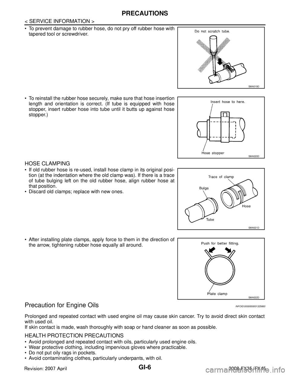
To prevent damage to rubber hose, do not pry off rubber hose withtapered tool or screwdriver.
To reinstall the rubber hose securely, make sure that hose insertion length and orientation is correct. (If tube is equipped with hose
stopper, insert rubber hose into tube until it butts up against hose
stopper.)
HOSE CLAMPING
If old rubber hose is re-used, install hose clamp in its original posi-tion (at the indentation where the old clamp was). If there is a trace
of tube bulging left on the old rubber hose, align rubber hose at
that position.
Discard old clamps; replace with new ones.
After installing plate clamps, apply force to them in the direction of the arrow, tightening rubber hose equally all around.
Precaution for Engine OilsINFOID:0000000001325660
Prolonged and repeated contact with used engine oil may cause skin cancer. Try to avoid direct skin contact
with used oil.
If skin contact is made, wash thoroughly with soap or hand cleaner as soon as possible.
HEALTH PROTECTION PRECAUTIONS
Avoid prolonged and repeated contact with oils, particularly used engine oils.
Wear protective clothing, including impervious gloves where practicable.
Do not put oily rags in pockets.
Avoid contaminating clothes, pa rticularly underpants, with oil.
SMA019D
SMA020D
SMA021D
SMA022D
3AA93ABC3ACD3AC03ACA3AC03AC63AC53A913A773A893A873A873A8E3A773A983AC73AC93AC03AC3
3A893A873A873A8F3A773A9D3AAF3A8A3A8C3A863A9D3AAF3A8B3A8C
Page 3107 of 3924
HEADLAMP - XENON TYPE -LT-5
< SERVICE INFORMATION >
C
DE
F
G H
I
J
L
M A
B
LT
N
O P
HEADLAMP - XENON TYPE -
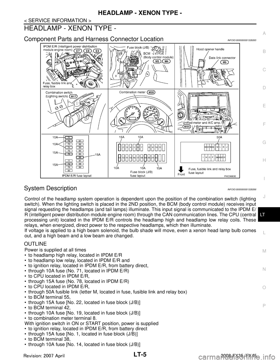
Component Parts and Har ness Connector LocationINFOID:0000000001328265
System DescriptionINFOID:0000000001328266
Control of the headlamp system operation is dependent upon t he position of the combination switch (lighting
switch). When the lighting switch is placed in the 2ND position, the BCM (body control module) receives input
signal requesting the headlamps (and tail lamps) illuminate. This input signal is communicated to the IPDM E/
R (intelligent power distribution module engine room) through the CAN communication lines. The CPU (central
processing unit) located in the IPDM E/R contro ls the headlamp high and headlamp low relay coils. These
relays, when energized, direct power to the respective headlamps, which then illuminate.
If voltage is applied to a high beam solenoid, the bulb shade will move, even a xenon head lamp bulb comes
out, and a high beam and a low beam are changed.
OUTLINE
Power is supplied at all times
to headlamp high relay, located in IPDM E/R
to headlamp low relay, located in IPDM E/R and
to ignition relay, located in IPDM E/R, from battery direct,
through 10A fuse (No. 71, located in IPDM E/R)
to CPU located in IPDM E/R,
through 15A fuse (No. 78, located in IPDM E/R)
to CPU located in IPDM E/R,
through 50A fusible link (letter M, located in fuse, fusible link and relay box)
to BCM terminal 55,
through 15A fuse [No. 22, located in fuse block (J/B)]
to BCM terminal 42,
through 10A fuse [No. 19, located in fuse block (J/B)]
to combination meter terminal 8.
With ignition switch in ON or START position, power is supplied
to ignition relay, located in IPDM E/R, from battery direct
through 15A fuse [No. 1, located in fuse block (J/B)]
to BCM terminal 38,
through 10A fuse [No. 14, located in fuse block (J/B)]
PKIC9683E
3AA93ABC3ACD3AC03ACA3AC03AC63AC53A913A773A893A873A873A8E3A773A983AC73AC93AC03AC3
3A893A873A873A8F3A773A9D3AAF3A8A3A8C3A863A9D3AAF3A8B3A8C
Page 3129 of 3924
HEADLAMP - XENON TYPE -LT-27
< SERVICE INFORMATION >
C
DE
F
G H
I
J
L
M A
B
LT
N
O P
Xenon Headlamp Trouble DiagnosisINFOID:0000000001328286
1.CHECK 1: XENON HEADLAMP LIGHTING
Install normal xenon bulb to corresponding xenon bulb headlamp, and check if lamp lights up.
OK or NG
OK >> Replace xenon bulb.
NG >> GO TO 2.
2.CHECK 2: XENON HEADLAMP LIGHTING
Install normal HID control unit to corresponding xenon headlamp, and check if lamp lights up.
OK or NG
OK >> Replace HID control unit.
NG >> GO TO 3.
3.CHECK 3: XENON HEADLAMP LIGHTING
Install normal xenon lamp housing assembly to corresponding xenon headlamp, and check if lamp lights up.
OK or NG
OK >> Replace xenon headlamp housing assembly. [Malfunction in starter (boosting circuit) in xenon headlamp housing]
NG >> INSPECTION END
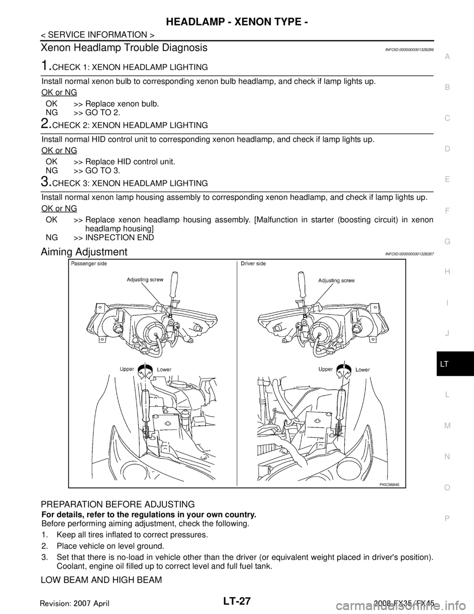
Aiming AdjustmentINFOID:0000000001328287
PREPARATION BEFORE ADJUSTING
For details, refer to the regulations in your own country.
Before performing aiming adjustment, check the following.
1. Keep all tires inflated to correct pressures.
2. Place vehicle on level ground.
3. Set that there is no-load in vehicle other than the driv er (or equivalent weight placed in driver's position).
Coolant, engine oil filled up to correct level and full fuel tank.
LOW BEAM AND HIGH BEAM
PKIC9684E
3AA93ABC3ACD3AC03ACA3AC03AC63AC53A913A773A893A873A873A8E3A773A983AC73AC93AC03AC3
3A893A873A873A8F3A773A9D3AAF3A8A3A8C3A863A9D3AAF3A8B3A8C
Page 3168 of 3924
LT-66
< SERVICE INFORMATION >
FRONT FOG LAMP
FRONT FOG LAMP
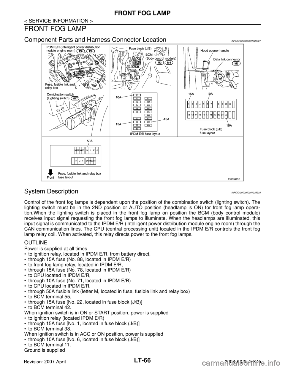
Component Parts and Harness Connector LocationINFOID:0000000001328327
System DescriptionINFOID:0000000001328328
Control of the front fog lamps is dependent upon the position of the combination switch (lighting switch). The
lighting switch must be in the 2ND position or AUTO position (headlamp is ON) for front fog lamp opera-
tion.When the lighting switch is placed in the front fog lamp on position the BCM (body control module)
receives input signal requesting the front fog lamps to illuminate. When the headlamps are illuminated, this
input signal is communicated to the IPDM E/R (inte lligent power distribution module engine room) through the
CAN communication lines. The CPU (central processing unit) located in the IPDM E/R controls the front fog
lamp relay coil. When activated, this relay directs power to the front fog lamps.
OUTLINE
Power is supplied at all times
to ignition relay, located in IP DM E/R, from battery direct,
through 15A fuse (No. 88, located in IPDM E/R)
to front fog lamp relay, located in IPDM E/R,
through 15A fuse (No. 78, located in IPDM E/R)
to CPU located in IPDM E/R,
through 10A fuse (No. 71, located in IPDM E/R)
to CPU located in IPDM E/R.
through 50A fusible link (letter M, located in fuse, fusible link and relay box)
to BCM terminal 55,
through 15A fuse [No. 22, located in fuse block (J/B)]
to BCM terminal 42.
When ignition switch is in ON or START position, power is supplied
to ignition relay (located IPDM E/R)
through 15A fuse [No. 1, located in fuse block (J/B)]
to BCM terminal 38.
When ignition switch is in ACC or ON position, power is supplied
through 10A fuse [No. 6, located in fuse block (J/B)]
to BCM terminal 11.
Ground is supplied
PKIB3475E
3AA93ABC3ACD3AC03ACA3AC03AC63AC53A913A773A893A873A873A8E3A773A983AC73AC93AC03AC3
3A893A873A873A8F3A773A9D3AAF3A8A3A8C3A863A9D3AAF3A8B3A8C
Page 3177 of 3924
FRONT FOG LAMPLT-75
< SERVICE INFORMATION >
C
DE
F
G H
I
J
L
M A
B
LT
N
O P
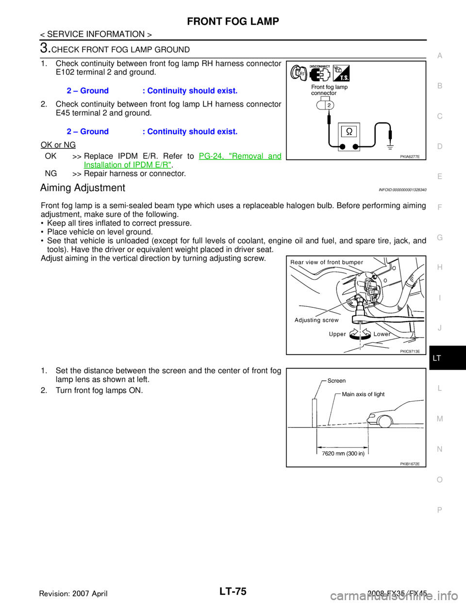
3.CHECK FRONT FOG LAMP GROUND
1. Check continuity between front fog lamp RH harness connector E102 terminal 2 and ground.
2. Check continuity between front fog lamp LH harness connector E45 terminal 2 and ground.
OK or NG
OK >> Replace IPDM E/R. Refer to PG-24, "Removal and
Installation of IPDM E/R".
NG >> Repair harness or connector.
Aiming AdjustmentINFOID:0000000001328340
Front fog lamp is a semi-sealed beam type which uses a replaceable halogen bulb. Before performing aiming
adjustment, make sure of the following.
Keep all tires inflated to correct pressure.
Place vehicle on level ground.
See that vehicle is unloaded (except for full levels of coolant, engine oil and fuel, and spare tire, jack, and tools). Have the driver or equivalent weight placed in driver seat.
Adjust aiming in the vertical direction by turning adjusting screw.
1. Set the distance between the scr een and the center of front fog
lamp lens as shown at left.
2. Turn front fog lamps ON. 2 – Ground : Continuity should exist.
2 – Ground : Continuity should exist.
PKIA6277E
PKIC9713E
PKIB1672E
3AA93ABC3ACD3AC03ACA3AC03AC63AC53A913A773A893A873A873A8E3A773A983AC73AC93AC03AC3
3A893A873A873A8F3A773A9D3AAF3A8A3A8C3A863A9D3AAF3A8B3A8C
Page 3220 of 3924
LT-118
< SERVICE INFORMATION >
PARKING, LICENSE PLATE AND TAIL LAMPS
PARKING, LICENSE PLATE AND TAIL LAMPS
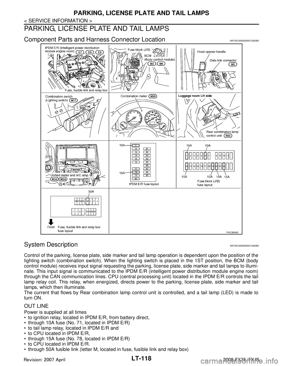
Component Parts and Harness Connector LocationINFOID:0000000001328382
System DescriptionINFOID:0000000001328383
Control of the parking, license plate, side marker and tail lamp operation is dependent upon the position of the
lighting switch (combination switch). When the lighting switch is placed in the 1ST position, the BCM (body
control module) receives input signal requesting the parki ng, license plate, side marker and tail lamps to illumi-
nate. This input signal is communicated to the IPDM E/R (intelligent power distribution module engine room)
through the CAN communication lines. CPU (central processi ng unit) located in the IPDM E/R controls the tail
lamp relay coil. This relay, when energized, directs pow er to the parking, license plate, side marker and tail
lamps, which then illuminate.
The current that flows by Rear combination lamp cont rol unit is controlled, and a tail lamp (LED) is made to
turn ON.
OUT LINE
Power is supplied at all times
to ignition relay, located in IP DM E/R, from battery direct,
through 10A fuse (No. 71, located in IPDM E/R)
to tail lamp relay, located in IPDM E/R and
to CPU located in IPDM E/R,
through 15A fuse (No. 78, located in IPDM E/R)
to CPU located in IPDM E/R.
through 50A fusible link (letter M, located in fuse, fusible link and relay box)
PKIC9694E
3AA93ABC3ACD3AC03ACA3AC03AC63AC53A913A773A893A873A873A8E3A773A983AC73AC93AC03AC3
3A893A873A873A8F3A773A9D3AAF3A8A3A8C3A863A9D3AAF3A8B3A8C
Page 3271 of 3924

ILLUMINATIONLT-169
< SERVICE INFORMATION >
C
DE
F
G H
I
J
L
M A
B
LT
N
O P
ILLUMINATION
System DescriptionINFOID:0000000001328422
Control of illumination lamps operation is dependent upon position of lighting switch (combination switch).
When lighting switch is placed in the 1ST or 2ND positi on (or if auto light system is activated), BCM (body con-
trol module) receives input signal requesting illuminati on lamps to illuminate. This input signal is communi-
cated to IPDM E/R (intelligent power distribution module engine room) through the CAN communication. The
CPU (central processing unit) located in the IPDM E/R co ntrols tail lamp relay coil. This relay, when energized,
directs power to illumination lamps, which then illuminate.
Power is supplied at all times
through 10A fuse (No. 71, located in IPDM E/R)
to tail lamp relay, located in IPDM E/R, and
to CPU located in IPDM E/R.
Power is also supplied at all times
through 50A fusible link (letter M, located in fuse, fusible link and relay box)
to BCM terminal 55,
through 15A fuse [No. 22 located in fuse block (J/B)]
to BCM terminal 42,
through 15A fuse (No. 78, located in IPDM E/R)
to CPU located in IPDM E/R,
through 10A fuse [No. 19 located in fuse block (J/B)]
to unified meter and A/C amp. terminal 21 and
to combination meter terminal 8.
With ignition switch in ON or START position, power is supplied
to ignition relay, located in IPDM E/R, from battery direct,
through 15A fuse [No. 1 located in fuse block (J/B)]
to BCM terminal 38,
through 10A fuse [No. 12, located in fuse block (J/B)]
to unified meter and A/C amp. terminal 22 and
to combination meter terminal 7.
With ignition switch in ACC or ON position, power is supplied
through 10A fuse [No. 6, located in fuse block (J/B)]
to combination meter terminal 4 and
to BCM terminal 11.
Ground is supplied
to BCM terminals 49 and 52
to unified meter and A/C amp. terminals 29 and 30, and
to combination meter terminals 5, 6, and 15
through grounds M35, M45, and M85,
to IPDM E/R terminals 38 and 60
through grounds E21, E50, and E51.
ILLUMINATION OPERATION BY LIGHTING SWITCH
With lighting switch in the 1ST or 2ND position (or if auto light system is activated), BCM receives input signal
requesting illumination lamps to illuminate. This input signal is communicated to IPDM E/R through the CAN
communication. The CPU located in the IPDM E/R controls tail lamp relay coil, which, when energized, directs
power
through IPDM E/R terminal 22
to glove box lamp terminal 1
to A/T device (illumination) terminal 11
to snow mode switch (illumination) terminal 5
to VDC off switch (illumination) terminal 3
to clock (illumination) terminal 3
to hazard switch (illumination) terminal 3
to heated seat switch (driver side) (illumination) terminal 5
to heated seat switch (passenger side) (illumination) terminal 5
to door mirror remote control switch (illumination) terminal 16
to LDW switch (illumination) terminal 5
to combination switch (spiral cable) terminal 26
to microphone terminal 2 (with telephone system)
3AA93ABC3ACD3AC03ACA3AC03AC63AC53A913A773A893A873A873A8E3A773A983AC73AC93AC03AC3
3A893A873A873A8F3A773A9D3AAF3A8A3A8C3A863A9D3AAF3A8B3A8C
Page 3286 of 3924

LU-1
ENGINE
C
DE
F
G H
I
J
K L
M
SECTION LU
A
LU
N
O P
CONTENTS
ENGINE LUBRICATION SYSTEM
VQ35DE
SERVICE INFORMATION .. ..........................
2
PRECAUTIONS .............................................. .....2
Precaution for Liquid Gasket ............................... ......2
PREPARATION ...................................................3
Special Service Tool ........................................... ......3
Commercial Service Tool ..........................................3
LUBRICATION SYSTEM ....................................4
Lubrication Circuit ............................................... ......4
System Chart ............................................................4
ENGINE OIL ........................................................5
Inspection ............................................................ ......5
Changing Engine Oil .................................................7
OIL FILTER .........................................................8
Removal and Installation ..................................... ......8
OIL FILTER BRACKET (AWD) ..........................10
Component .......................................................... ....10
Removal and Installation .........................................10
OIL COOLER ......................................................12
Component .......................................................... ....12
Removal and Installation .........................................13
OIL PUMP ...........................................................15
Component .......................................................... ....15
Removal and Installation .........................................15
Disassembly and Assembly ....................................15
SERVICE DATA AND SPECIFICATIONS
(SDS) ..................................................................
18
Standard and Limit .............................................. ....18
VK45DE
SERVICE INFORMATION .. .........................
19
PRECAUTIONS .................................................19
Precaution for Liquid Gasket ............................... ....19
PREPARATION .................................................20
Special Service Tool ................................................20
Commercial Service Tool ........................................20
LUBRICATION SYSTEM ..................................21
Lubrication Circuit ....................................................21
System Chart ...........................................................22
ENGINE OIL ......................................................23
Inspection ................................................................23
Changing Engine Oil ................................................24
OIL FILTER .......................................................26
Removal and Installation .........................................26
OIL COOLER ....................................................27
Component ..............................................................27
Removal and Installation .........................................27
OIL PUMP .........................................................29
Component ..............................................................29
Removal and Installation .........................................29
Disassembly and Assembly .....................................30
SERVICE DATA AND SPECIFICATIONS
(SDS) .................................................................
32
Standard and Limit ..................................................32
3AA93ABC3ACD3AC03ACA3AC03AC63AC53A913A773A893A873A873A8E3A773A983AC73AC93AC03AC3
3A893A873A873A8F3A773A9D3AAF3A8A3A8C3A863A9D3AAF3A8B3A8C