2008 INFINITI FX35 speedometer
[x] Cancel search: speedometerPage 1133 of 3924
COMBINATION METERSDI-7
< SERVICE INFORMATION >
C
DE
F
G H
I
J
L
M A
B
DI
N
O P
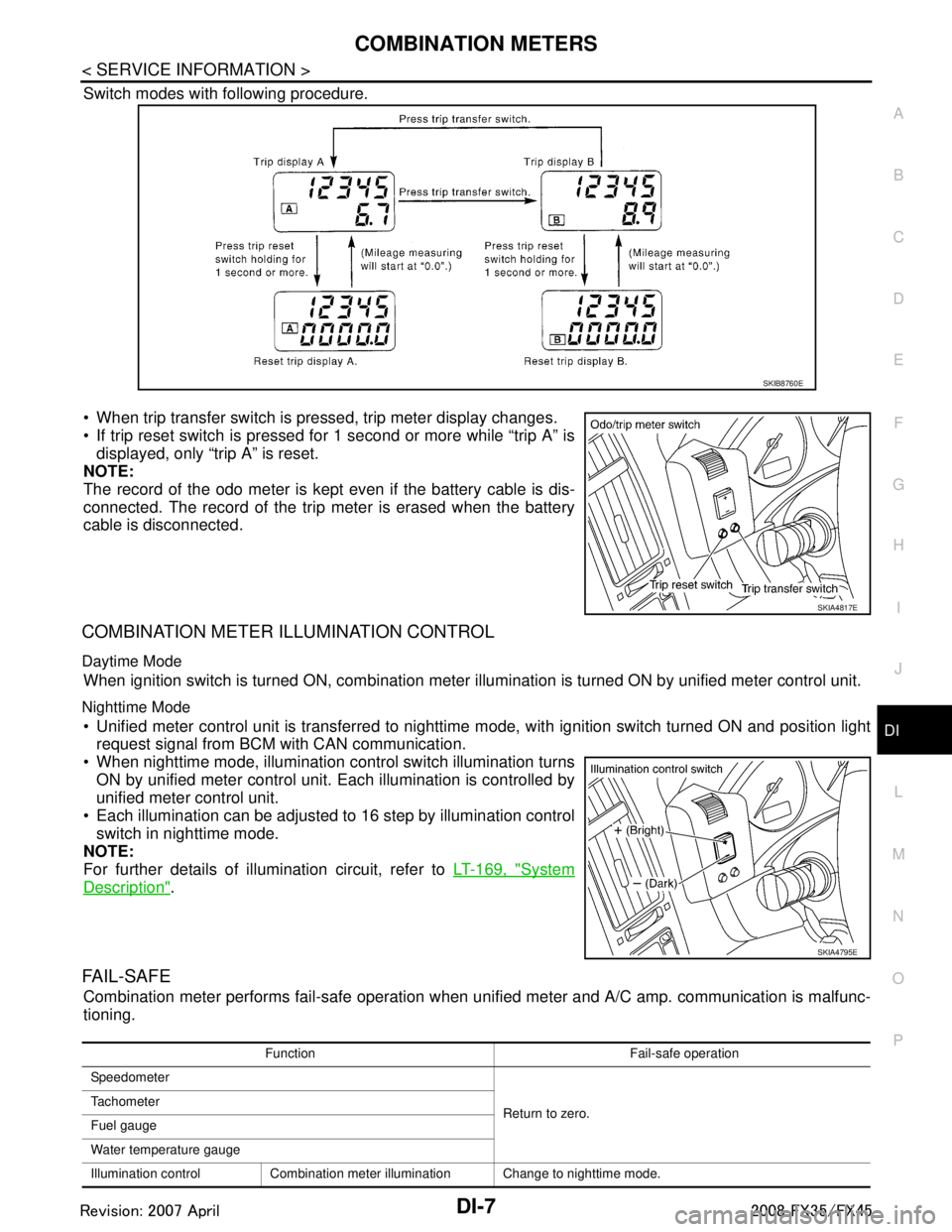
Switch modes with following procedure.
When trip transfer switch is pressed, trip meter display changes.
If trip reset switch is pressed for 1 second or more while “trip A” is displayed, only “trip A” is reset.
NOTE:
The record of the odo meter is kept even if the battery cable is dis-
connected. The record of the trip meter is erased when the battery
cable is disconnected.
COMBINATION METER ILLUMINATION CONTROL
Daytime Mode
When ignition switch is turned ON, combination meter il lumination is turned ON by unified meter control unit.
Nighttime Mode
Unified meter control unit is transferred to nighttime mode, with ignitio\
n switch turned ON and position light
request signal from BCM with CAN communication.
When nighttime mode, illumination c ontrol switch illumination turns
ON by unified meter control unit. Each illumination is controlled by
unified meter control unit.
Each illumination can be adjusted to 16 step by illumination control switch in nighttime mode.
NOTE:
For further details of illumination circuit, refer to LT-169, "
System
Description".
FA I L - S A F E
Combination meter performs fail-safe operation when unified meter and A/C amp. communication is malfunc-
tioning.
SKIB8760E
SKIA4817E
SKIA4795E
Function Fail-safe operation
Speedometer
Return to zero.
Tachometer
Fuel gauge
Water temperature gauge
Illumination control Combination meter illumination Change to nighttime mode.
3AA93ABC3ACD3AC03ACA3AC03AC63AC53A913A773A893A873A873A8E3A773A983AC73AC93AC03AC3
3A893A873A873A8F3A773A9D3AAF3A8A3A8C3A863A9D3AAF3A8B3A8C
Page 1139 of 3924
COMBINATION METERSDI-13
< SERVICE INFORMATION >
C
DE
F
G H
I
J
L
M A
B
DI
N
O P
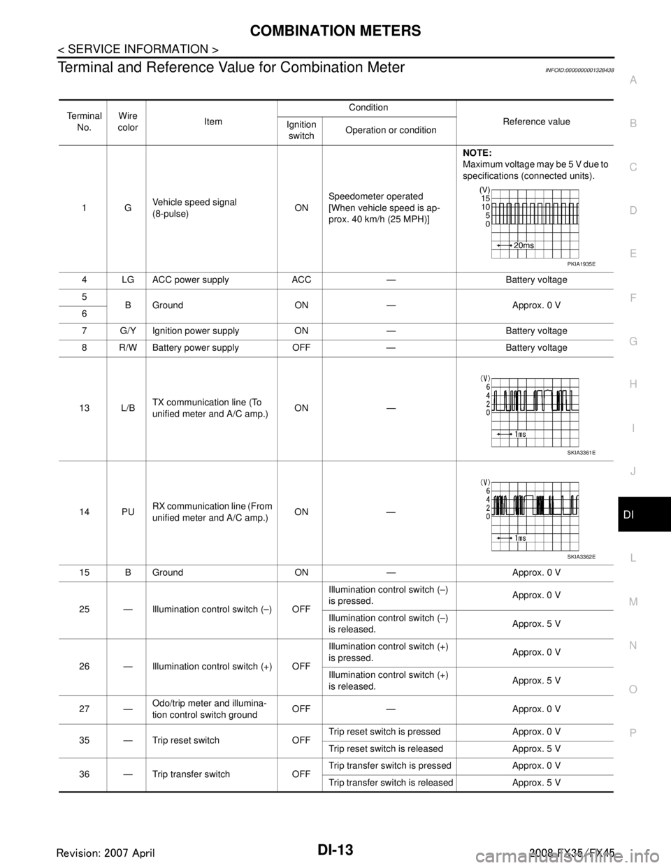
Terminal and Reference Va lue for Combination MeterINFOID:0000000001328438
Te r m i n a l
No. Wire
color Item Condition
Reference value
Ignition
switch Operation or condition
1G Vehicle speed signal
(8-pulse)
ONSpeedometer operated
[When vehicle speed is ap-
prox. 40 km/h (25 MPH)] NOTE:
Maximum voltage may be 5 V due to
specifications (connected units).
4 LG ACC power supply ACC — Battery voltage
5 B Ground ON — Approx. 0 V
6
7 G/Y Ignition power supply ON — Battery voltage
8 R/W Battery power supply OFF — Battery voltage
13 L/B TX communication line (To
unified meter and A/C amp.)
ON —
14 PU RX communication line (From
unified meter and A/C amp.) ON —
15 B Ground ON — Approx. 0 V
25 — Illumination control switch (–) OFF Illumination control switch (–)
is pressed.
Approx. 0 V
Illumination control switch (–)
is released. Approx. 5 V
26 — Illumination control switch (+) OFF Illumination control switch (+)
is pressed.
Approx. 0 V
Illumination control switch (+)
is released. Approx. 5 V
27 — Odo/trip meter and illumina-
tion control switch ground
OFF — Approx. 0 V
35 — Trip reset switch OFF Trip reset switch is pressed Approx. 0 V
Trip reset switch is released Approx. 5 V
36 — Trip transfer switch OFF Trip transfer switch is pressed Approx. 0 V
Trip transfer switch is released Approx. 5 V
PKIA1935E
SKIA3361E
SKIA3362E
3AA93ABC3ACD3AC03ACA3AC03AC63AC53A913A773A893A873A873A8E3A773A983AC73AC93AC03AC3
3A893A873A873A8F3A773A9D3AAF3A8A3A8C3A863A9D3AAF3A8B3A8C
Page 1140 of 3924
DI-14
< SERVICE INFORMATION >
COMBINATION METERS
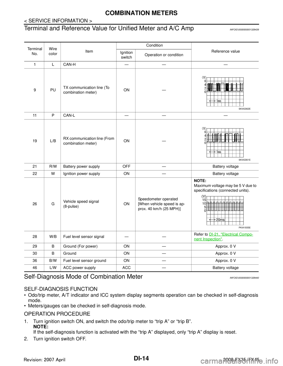
Terminal and Reference Value for Unified Meter and A/C Amp
INFOID:0000000001328439
Self-Diagnosis Mode of Combination MeterINFOID:0000000001328440
SELF-DIAGNOSIS FUNCTION
Odo/trip meter, A/T indicator and ICC system disp lay segments operation can be checked in self-diagnosis
mode.
Meters/gauges can be checked in self-diagnosis mode.
OPERATION PROCEDURE
1. Turn ignition switch ON, and switch the odo/trip meter to “trip A” or “trip B”. NOTE:
If the self-diagnosis function is activated with the “t rip A” displayed, only “trip A” display is reset.
2. Turn ignition switch OFF.
Te r m i n a l No. Wire
color Item Condition
Reference value
Ignition
switch Operation or condition
1 L CAN-H — — —
9PU TX communication line (To
combination meter) ON —
11 P C A N - L — — —
19 L/B RX communication line (From
combination meter) ON —
21 R/W Battery power supply OFF — Battery voltage
22 W Ignition power supply ON — Battery voltage
26 G Vehicle speed signal
(8-pulse)
ONSpeedometer operated
[When vehicle speed is ap-
prox. 40 km/h (25 MPH)] NOTE:
Maximum voltage may be 5 V due to
specifications (connected units).
28 W/B Fuel level sensor signal — — Refer to
DI-21, "
Electrical Compo-
nent Inspection".
29 B Ground (For power) ON — Approx. 0 V
30 B Ground ON — Approx. 0 V
36 B/W Fuel level sensor ground ON — Approx. 0 V
46 L/W ACC power supply ACC — Battery voltage
SKIA3362E
SKIA3361E
PKIA1935E
3AA93ABC3ACD3AC03ACA3AC03AC63AC53A913A773A893A873A873A8E3A773A983AC73AC93AC03AC3
3A893A873A873A8F3A773A9D3AAF3A8A3A8C3A863A9D3AAF3A8B3A8C
Page 1142 of 3924
DI-16
< SERVICE INFORMATION >
COMBINATION METERS
Perform self-diagnosis mode of combination meter. Refer to DI-14, "Self-Diagnosis Mode of Combination
Meter".
Does self-diagnosis function operate?
YES >> GO TO 2.
NO >> GO TO 3.
2.CHECK UNIFIED METER AND A/C AMP. (CONSULT-III)
Perform self-diagnosis of unified meter and A/C amp. Refer to DI-27, "
CONSULT-III Function (METER/M&A)".
Self-diagnosis results
No malfunction detected >> INSPECTION END
Malfunction detected >> Check applicable parts, and repair or replace corresponding parts.
3.CHECK POWER SUPPLY AND GROUND CIRCUIT OF COMBINATION METER
Check power supply and ground circuit of combination meter. Refer to DI-16, "
Power Supply and Ground Cir-
cuit Inspection".
OK or NG
OK >> Check odo/trip meter switch. Refer to DI-21, "Odo/Trip Meter and Illumination Control Switch
Inspection".
NG >> Repair malfunctioning part.
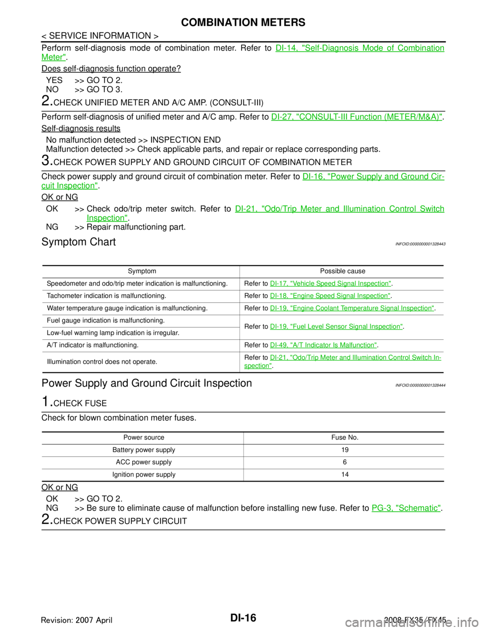
Symptom ChartINFOID:0000000001328443
Power Supply and Ground Circuit InspectionINFOID:0000000001328444
1.CHECK FUSE
Check for blown combination meter fuses.
OK or NG
OK >> GO TO 2.
NG >> Be sure to eliminate cause of malfunction before installing new fuse. Refer to PG-3, "
Schematic".
2.CHECK POWER SUPPLY CIRCUIT
Symptom Possible cause
Speedometer and odo/trip meter indication is malfunctioning. Refer to DI-17, "
Vehicle Speed Signal Inspection".
Tachometer indication is malfunctioning. Refer to DI-18, "
Engine Speed Signal Inspection".
Water temperature gauge indication is malfunctioning. Refer to DI-19, "
Engine Coolant Temperature Signal Inspection".
Fuel gauge indication is malfunctioning. Refer to DI-19, "
Fuel Level Sensor Signal Inspection".
Low-fuel warning lamp indication is irregular.
A/T indicator is malfunctioning. Refer to DI-49, "
A/T Indicator Is Malfunction".
Illumination control does not operate. Refer to
DI-21, "
Odo/Trip Meter and Illumination Control Switch In-
spection".
Power source Fuse No.
Battery power supply 19 ACC power supply 6
Ignition power supply 14
3AA93ABC3ACD3AC03ACA3AC03AC63AC53A913A773A893A873A873A8E3A773A983AC73AC93AC03AC3
3A893A873A873A8F3A773A9D3AAF3A8A3A8C3A863A9D3AAF3A8B3A8C
Page 1143 of 3924
COMBINATION METERSDI-17
< SERVICE INFORMATION >
C
DE
F
G H
I
J
L
M A
B
DI
N
O P
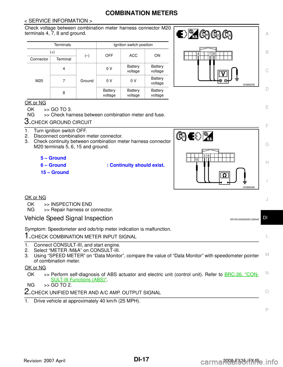
Check voltage between combination meter harness connector M20
terminals 4, 7, 8 and ground.
OK or NG
OK >> GO TO 3.
NG >> Check harness between combination meter and fuse.
3.CHECK GROUND CIRCUIT
1. Turn ignition switch OFF.
2. Disconnect combination meter connector.
3. Check continuity between combination meter harness connector M20 terminals 5, 6, 15 and ground.
OK or NG
OK >> INSPECTION END
NG >> Repair harness or connector.
Vehicle Speed Signal InspectionINFOID:0000000001328445
Symptom: Speedometer and odo/trip meter indication is malfunction.
1.CHECK COMBINATION METER INPUT SIGNAL
1. Connect CONSULT-III, and start engine.
2. Select “METER /M&A” on CONSULT-III.
3. Using “SPEED METER” on “Data Moni tor”, compare the value of “Data Monitor” with speedometer pointer
of combination meter.
OK or NG
OK >> Perform self-diagnosis of ABS actuator and electric unit (control unit). Refer to BRC-26, "CON-
SULT-III Functions (ABS)".
NG >> GO TO 2.
2.CHECK UNIFIED METER AND A/ C AMP. OUTPUT SIGNAL
1. Drive vehicle at approximately 40 km/h (25 MPH).
Terminals Ignition switch position
(+) (–) OFF ACC ON
Connector Terminal
M20 4
Ground 0 V
Battery
voltage Battery
voltage
70 V0 V Battery
voltage
8 Battery
voltage Battery
voltage Battery
voltage
SKIB8525E
5 – Ground
: Continuity should exist.
6 – Ground
15 – Ground
SKIB8526E
3AA93ABC3ACD3AC03ACA3AC03AC63AC53A913A773A893A873A873A8E3A773A983AC73AC93AC03AC3
3A893A873A873A8F3A773A9D3AAF3A8A3A8C3A863A9D3AAF3A8B3A8C
Page 1210 of 3924
DI-84
< SERVICE INFORMATION >
LANE DEPARTURE WARNING SYSTEM
Preliminary Check
INFOID:0000000001328502
1.CHECK CAMERA LENS AND WINDSHIELD
Are camera lens and windshield contaminated with foreign materials?
YES >> Clean camera lens and windshield.
NO >> GO TO 2.
2.CHECK CAMERA UNIT IN STALLATION CONDITION
Check camera unit installation condition (installat ion position, properly tightened, a bent bracket).
OK or NG
OK >> GO TO 3.
NG >> Install camera unit properly, and adjust camera aiming. Refer to DI-71, "
Camera Aiming Adjust-
ment".
3.CHECK VEHICLE HEIGHT
Check vehicle height. Refer to GI-47, "
Dimensions".
Is vehicle height appropriate?
OK >> GO TO 4.
NG >> Repair vehicle to appropriate height.
4.CHECK LDW CAMERA UNIT (CONSULT-III)
Perform self-diagnosis of LDW camera unit. Refer to DI-81, "
CONSULT-III Function (LDW)".
Self
-diagnosis results
No malfunction detected >> GO TO 5.
Malfunction detected >> Check applicable parts, and repair or replace corresponding parts.
5.CHECK COMBINATION METER
Check combination meter function.
Do speedometer and turn signal indicator normal function?
YES >> INSPECTION END
NO >> Check combination meter. Refer to DI-15, "
Trouble Diagnosis".
Power Supply and Ground Circuit InspectionINFOID:0000000001328503
1.CHECK FUSE
Check for blown LDW camera unit fuse.
Symptom Diagnoses/Service procedure
LDW system is not activated.
(LDW system ON indicator turns ON/OFF.) Perform the following inspections.
1.
DI-86, "
LDW Chime Circuit Inspection"
2.DI-90, "LDW Indicator Lamp Circuit Inspection"
Replace LDW camera unit, check function in the above inspections.
LDW system does not turn ON/OFF.
(LDW system ON indicator does not turn ON/OFF.) Perform
DI-88, "
LDW Switch Circuit Inspection".
Replace LDW camera unit, check function in the above inspection.
Warning functions are untimely. (Example)
Warning does not function when driving on lane markers.
Warning functions when driving in a lane.
Different position from actual condition functions. Perform
DI-71, "
Camera Aiming Adjustment".
Functions when changing the course to the turn signal direction. Perform
DI-91, "
Turn Signal Input Inspection".
Replace LDW camera unit, check function in the above inspection.
LDW indicator lamp does not illuminate with ignition switch ON. Perform
DI-90, "
LDW Indicator Lamp Circuit Inspection".
Replace LDW camera unit, check function in the above inspection.
3AA93ABC3ACD3AC03ACA3AC03AC63AC53A913A773A893A873A873A8E3A773A983AC73AC93AC03AC3
3A893A873A873A8F3A773A9D3AAF3A8A3A8C3A863A9D3AAF3A8B3A8C
Page 1368 of 3924
![INFINITI FX35 2008 Service Manual
EC-128
< SERVICE INFORMATION >[VQ35DE]
TROUBLE DIAGNOSIS
HO2S2 (B1)
HO2S2 (B2) Revving engine from idle to 3,000 rpm quickly after the following conditions
are met
- Engine: After warming up
- Keep INFINITI FX35 2008 Service Manual
EC-128
< SERVICE INFORMATION >[VQ35DE]
TROUBLE DIAGNOSIS
HO2S2 (B1)
HO2S2 (B2) Revving engine from idle to 3,000 rpm quickly after the following conditions
are met
- Engine: After warming up
- Keep](/manual-img/42/57017/w960_57017-1367.png)
EC-128
< SERVICE INFORMATION >[VQ35DE]
TROUBLE DIAGNOSIS
HO2S2 (B1)
HO2S2 (B2) Revving engine from idle to 3,000 rpm quickly after the following conditions
are met
- Engine: After warming up
- Keeping the engine speed between 3,500 and 4,000 rpm for 1 minute and at idle for 1 minute under no load 0 - 0.3V
←→ Approx. 0.6 - 1.0V
HO2S2 MNTR(B1)
HO2S2 MNTR(B2) LEAN
←→ RICH
VHCL SPEED SE Turn drive wheels and compare CONSULT-III value with the speedometer
indication. Almost the same speed as the
speedometer indication
BATTERY VOLT Ignition switch: ON (Engine stopped) 11 - 14V
ACCEL SEN 1 Ignition switch: ON
(Engine stopped) Accelerator pedal: Fully released 0.5 - 1.0V
Accelerator pedal: Fully depressed 4.0 - 4.8V
ACCEL SEN 2* Ignition switch: ON
(Engine stopped) Accelerator pedal: Fully released 0.3 - 1.2V
Accelerator pedal: Fully depressed 3.9 - 4.8V
TP SEN 1-B1
TP SEN 2-B1* Ignition switch: ON
(Engine stopped)
Selector lever: D Accelerator pedal:
Fully released More than 0.36V
Accelerator pedal: Fully depressed Less than 4.75V
EVAP SYS PRES Ignition switch: ON Approx. 1.8 - 4.8V
START SIGNAL Ignition switch: ON → START → ON OFF → ON → OFF
CLSD THL POS Ignition switch: ON
(Engine stopped) Accelerator pedal: Fully released ON
Accelerator pedal: Slightly depressed OFF
AIR COND SIG Engine: After warming up, idle the
engine Air conditioner switch: OFF OFF
Air conditioner switch: ON
(Compressor operates.)
ON
P/N POSI SW Ignition switch: ON Selector lever: P or N ON
Selector lever: Except above OFF
PW/ST SIGNAL Engine: After warming up, idle the
engine Steering wheel: Not being turned OFF
Steering wheel: Being turned ON
LOAD SIGNAL Ignition switch: ON Rear window defogger switch is ON
and/or lighting switch is in 2nd
ON
Rear window defogger switch is OFF
and lighting switch is OFF OFF
IGNITION SW Ignition switch: ON → OFF → ON ON → OFF → ON
HEATER FAN SW Engine: After warming up, idle the
engine Heater fan: Operating. ON
Heater fan: Not operating OFF
BRAKE SW Ignition switch: ON Brake pedal: Fully released OFF
Brake pedal: Slightly depressed ON
INJ PULSE-B1
INJ PULSE-B2 Engine: After warming up
Selector lever: P or N
Air conditioner switch: OFF
No load Idle 2.0 - 3.0 msec
2,000 rpm 1.9 - 2.9 msec
IGN TIMING Engine: After warming up
Selector lever: P or N
Air conditioner switch: OFF
No load Idle 13
° - 18 ° BTDC
2,000 rpm 25 ° - 45 ° BTDC
CAL/LD VALUE Engine: After warming up
Selector lever: P or N
Air conditioner switch: OFF
No load Idle 5% - 35%
2,500 rpm 5% - 35%
MASS AIRFLOW Engine: After warming up
Selector lever: P or N
Air conditioner switch: OFF
No load Idle 2.0 - 6.0 g·m/s
2,500 rpm 7.0 - 20.0 g·m/s
MONITOR ITEM CONDITION SPECIFICATION
3AA93ABC3ACD3AC03ACA3AC03AC63AC53A913A773A893A873A873A8E3A773A983AC73AC93AC03AC3
3A893A873A873A8F3A773A9D3AAF3A8A3A8C3A863A9D3AAF3A8B3A8C
Page 1369 of 3924
![INFINITI FX35 2008 Service Manual
TROUBLE DIAGNOSISEC-129
< SERVICE INFORMATION > [VQ35DE]
C
D
E
F
G H
I
J
K L
M A
EC
NP
O
PURG VOL C/V
Engine: After warming up
Selector lever: P or N
Air conditioner switch: OFF
No load Idle
INFINITI FX35 2008 Service Manual
TROUBLE DIAGNOSISEC-129
< SERVICE INFORMATION > [VQ35DE]
C
D
E
F
G H
I
J
K L
M A
EC
NP
O
PURG VOL C/V
Engine: After warming up
Selector lever: P or N
Air conditioner switch: OFF
No load Idle](/manual-img/42/57017/w960_57017-1368.png)
TROUBLE DIAGNOSISEC-129
< SERVICE INFORMATION > [VQ35DE]
C
D
E
F
G H
I
J
K L
M A
EC
NP
O
PURG VOL C/V
Engine: After warming up
Selector lever: P or N
Air conditioner switch: OFF
No load Idle
(Accelerator pedal is not depressed
even slightly, after engine starting)
0%
2,000 rpm —
INT/V TIM(B1)
INT/V TIM(B2) Engine: After warming up
Selector lever: P or N
Air conditioner switch: OFF
No load Idle
−5° - 5 °CA
When revving engine up to 2,000 rpm
quickly Approx. 0
° - 30 °CA
INT/V SOL(B1)
INT/V SOL(B2) Engine: After warming up
Selector lever: P or N
Air conditioner switch: OFF
No load Idle 0% - 2%
When revving engine up to 2,000 rpm
quickly
Approx. 0% - 50%
AIR COND RLY Engine: After warming up, idle the
engine Air conditioner switch: OFF OFF
Air conditioner switch: ON
(Compressor operates)
ON
FUEL PUMP RLY For 1 second after turning ignition switch ON
Engine running or cranking
ON
Except above conditions OFF
VENT CONT/V Ignition switch: ON OFF
THRTL RELAY Ignition switch: ON ON
COOLING FAN Engine: After warming up, idle the
engine
Air conditioner switch: OFF Engine coolant temperature is 97
°C
(207 °F) or less OFF
Engine coolant temperature is be-
tween 98 °C (208 °F) and 99 °C (210 °F) LOW
Engine coolant temperature is be-
tween 100 °C (212 °F) and 104 °C
(219 °F) MID
Engine coolant temperature is 105 °C
(221 °F) or more HI
HO2S2 HTR (B1)
HO2S2 HTR (B2) Engine speed is below 3,600 rpm after the following conditions are met.
- Engine: After warming up
- Keeping the engine speed between 3,500 and 4,000 rpm for 1 minute and
at idle for 1 minute under no load ON
Engine speed: Above 3,600 rpm OFF
I/P PULLY SPD Vehicle speed: More than 20 km/h (12 MPH) Almost the same speed as the
speedometer indication
VEHICLE SPEED Turn drive wheels and compare the CONSULT-III value with speedometer
indication. Almost the same speed as the
speedometer indication
TRVL AFTER MIL Ignition switch: ON Vehicle has traveled after MIL has
turned ON.0 - 65,535 km
(0 - 40,7
23 mile)
SNOW MODE SW Ignition switch: ON Snow mode switch: ON ON
Snow mode switch: OFF OFF
A/F S1 HTR(B1)
A/F S1 HTR(B2) Engine: After warming up, idle the engine 0 - 100%
AC PRESS SEN Engine: Idle
Both A/C switch and blower fan switch: ON
(Compressor operates) 1.0 - 4.0V
VHCL SPEED SE Turn drive wheels and compare speedometer indication with the CON-
SULT-III value. Almost the same speed as the
CONSULT-III value
SET VHCL SPD Engine: Running ASCD: Operating. The preset vehicle speed is dis-
played.
MAIN SW Ignition switch: ON MAIN switch: Pressed ON
MAIN switch: Released OFF
MONITOR ITEM CONDITION SPECIFICATION
3AA93ABC3ACD3AC03ACA3AC03AC63AC53A913A773A893A873A873A8E3A773A983AC73AC93AC03AC3
3A893A873A873A8F3A773A9D3AAF3A8A3A8C3A863A9D3AAF3A8B3A8C