2008 INFINITI FX35 section atc
[x] Cancel search: section atcPage 2878 of 3924

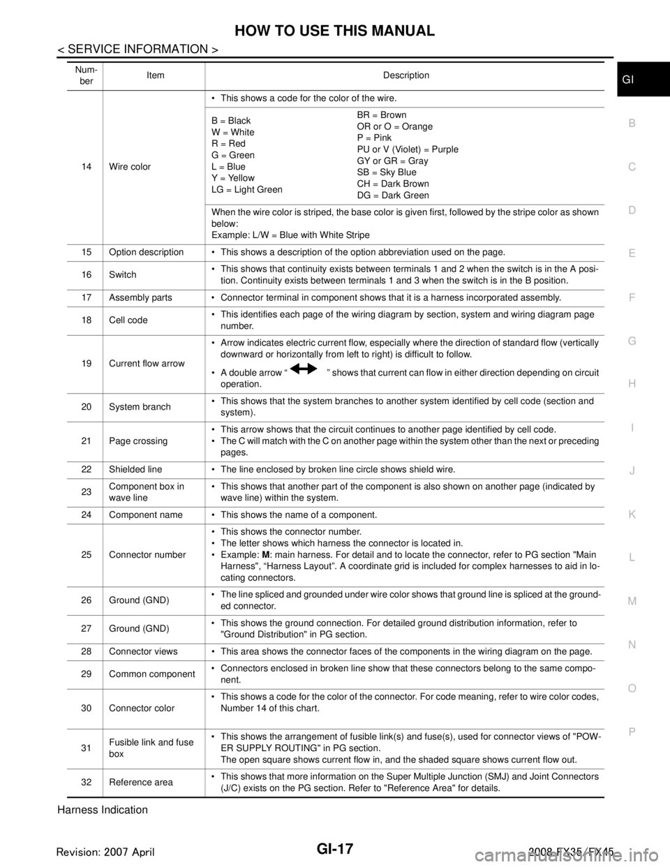
GI-16
< SERVICE INFORMATION >
HOW TO USE THIS MANUAL
Optional Splice
DESCRIPTION
SGI942
Num-ber Item Description
1 Power condition This shows the condition when the system receives battery positive voltage (can be operated).
2Fusible link The double line shows that this is a fusible link.
The open circle shows current flow in, and the shaded circle shows current flow out.
3 Fusible link/fuse loca-
tion This shows the location of the fusible link or fuse in the fusible link or fuse box. For arrange-
ment, refer to PG section, POWER SUPPLY ROUTING.
4Fuse The single line shows that this is a fuse.
The open circle shows current flow in, and the shaded circle shows current flow out.
5 Current rating This shows the current rating of the fusible link or fuse.
6 Connectors This shows that connector E3 is female and connector M1 is male.
The G/R wire is located in the 1A terminal of both connectors.
Terminal number with an alphabet (1A, 5B, etc.) indicates that the connector is SMJ connector.
Refer to PG section, SMJ (SUPER MULTIPLE JUNCTION).
7 Optional splice The open circle shows that the splice is optional depending on vehicle application.
8 Splice The shaded circle shows that the splice is always on the vehicle.
9 Page crossing This arrow shows that the circuit continues to an adjacent page.
The A will match with the A on the preceding or next page.
10 Common connector The dotted lines between terminals show that these terminals are part of the same connector. 11 Option abbreviation This shows that the circuit is optional depending on vehicle application.
12 Relay This shows an internal representation of the relay. For details, refer to PG section, STAN-
DARDIZED RELAY.
13 Connectors This shows that the connector is connected to the body or a terminal with bolt or nut.
3AA93ABC3ACD3AC03ACA3AC03AC63AC53A913A773A893A873A873A8E3A773A983AC73AC93AC03AC3
3A893A873A873A8F3A773A9D3AAF3A8A3A8C3A863A9D3AAF3A8B3A8C
Page 2879 of 3924

HOW TO USE THIS MANUALGI-17
< SERVICE INFORMATION >
C
DE
F
G H
I
J
K L
M B
GI
N
O P
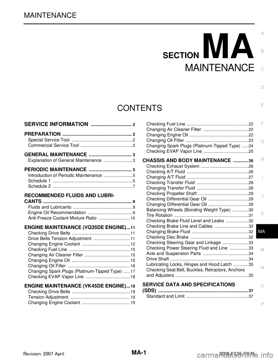
Harness Indication
14 Wire color This shows a code for the color of the wire.
B = Black
W = White
R = Red
G = Green
L = Blue
Y = Yellow
LG = Light Green BR = Brown
OR or O = Orange
P = Pink
PU or V (Violet) = Purple
GY or GR = Gray
SB = Sky Blue
CH = Dark Brown
DG = Dark Green
When the wire color is striped, the base color is given first, followed by the stripe color as shown
below:
Example: L/W = Blue with White Stripe
15 Option description This shows a description of the option abbreviation used on the page.
16 Switch This shows that continuity exists between terminals 1 and 2 when the switch is in the A posi-
tion. Continuity exists between terminals 1 and 3 when the switch is in the B position.
17 Assembly parts Connector terminal in component shows that it is a harness incorporated assembly.
18 Cell code This identifies each page of the wiring diagram by section, system and wiring diagram page
number.
19 Current flow arrow Arrow indicates electric current flow, especially where the direction of standard flow (vertically
downward or horizontally from left to right) is difficult to follow.
A double arrow “ ” shows that current can flow in either direction depending on circuit operation.
20 System branch This shows that the system branches to another system identified by cell code (section and
system).
21 Page crossing This arrow shows that the circuit continues to another page identified by cell code.
The C will match with the C on another page within the system other than the next or preceding
pages.
22 Shielded line The line enclosed by broken line circle shows shield wire.
23 Component box in
wave line This shows that another part of the component is also shown on another page (indicated by
wave line) within the system.
24 Component name This shows the name of a component.
25 Connector number This shows the connector number.
The letter shows which harness the connector is located in.
Example:
M: main harness. For detail and to locate the connector, refer to PG section "Main
Harness", “Harness Layout”. A coordinate grid is included for complex harnesses to aid in lo-
cating connectors.
26 Ground (GND) The line spliced and grounded under wire color shows that ground line is spliced at the ground-
ed connector.
27 Ground (GND) This shows the ground connection. For detailed ground distribution information, refer to
"Ground Distribution" in PG section.
28 Connector views This area shows the connector faces of the components in the wiring diagram on the page.
29 Common component Connectors enclosed in broken line show that these connectors belong to the same compo-
nent.
30 Connector color This shows a code for the color of the connector. For code meaning, refer to wire color codes,
Number 14 of this chart.
31 Fusible link and fuse
box This shows the arrangement of fusible link(s) and fuse(s), used for connector views of "POW-
ER SUPPLY ROUTING" in PG section.
The open square shows current flow in, and the shaded square shows current flow out.
32 Reference area This shows that more information on the Super Multiple Junction (SMJ) and Joint Connectors
(J/C) exists on the PG section. Refer to "Reference Area" for details.
Num-
ber Item Description
3AA93ABC3ACD3AC03ACA3AC03AC63AC53A913A773A893A873A873A8E3A773A983AC73AC93AC03AC3
3A893A873A873A8F3A773A9D3AAF3A8A3A8C3A863A9D3AAF3A8B3A8C
Page 3318 of 3924

MA-1
MAINTENANCE
C
DE
F
G H
I
J
K
M
SECTION MA
A
B
MA
N
O P
CONTENTS
MAINTENANCE
SERVICE INFORMATION .. ..........................2
PREPARATION .............................................. .....2
Special Service Tool ........................................... ......2
Commercial Service Tool ..........................................2
GENERAL MAINTENANCE ................................3
Explanation of General Maintenance .................. ......3
PERIODIC MAINTENANCE ................................5
Introduction of Periodic Maintenance .................. ......5
Schedule 1 ................................................................5
Schedule 2 ................................................................7
RECOMMENDED FLUIDS AND LUBRI-
CANTS .................................................................
9
Fluids and Lubricants .......................................... ......9
Engine Oil Recommendation ....................................9
Anti-Freeze Coolant Mixture Ratio ..........................10
ENGINE MAINTENANCE (VQ35DE ENGINE) ....11
Checking Drive Belts ........................................... ....11
Drive Belts Tension Adjustment ..............................11
Changing Engine Coolant .......................................12
Checking Fuel Line .................................................15
Changing Air Cleaner Filter .....................................15
Changing Engine Oil ...............................................15
Changing Oil Filter ..................................................16
Changing Spark Plugs (Platinum-Tipped Type) ......17
Checking EVAP Vapor Line ....................................18
ENGINE MAINTENANCE (VK45DE ENGINE) ....19
Checking Drive Belts ........................................... ....19
Tension Adjustment ................................................19
Changing Engine Coolant .......................................19
Checking Fuel Line .............................................. ....22
Changing Air Cleaner Filter .....................................22
Changing Engine Oil ................................................22
Changing Oil Filter ...................................................23
Changing Spark Plugs (Platinum-Tipped Type) ......24
Checking EVAP Vapor Line .....................................25
CHASSIS AND BODY MAINTENANCE ...........26
Checking Exhaust System ................................... ....26
Checking A/T Fluid ..................................................26
Changing A/T Fluid ..................................................27
Checking Transfer Fluid ..........................................28
Changing Transfer Fluid ..........................................28
Checking Propeller Shaft .........................................29
Checking Differential Gear Oil .................................29
Changing Differential Gear Oil .................................29
Balancing Wheels (Bonding Weight Type) ..............30
Tire Rotation ............................................................31
Checking Brake Fluid Level and Leaks ...................32
Checking Brake Line and Cables ............................32
Changing Brake Fluid ..............................................32
Checking Disc Brake ...............................................32
Checking Steering Gear and Linkage ......................33
Checking Power Steering Fluid and Line ................33
Axle and Suspension Parts .....................................34
Drive Shaft ...............................................................34
Lubricating Locks, Hinges and Hood Latch .............35
Checking Seat Belt, Buckles, Retractors, Anchors
and Adjusters ...........................................................
35
SERVICE DATA AND SPECIFICATIONS
(SDS) .................................................................
37
Standard and Limit ..................................................37
3AA93ABC3ACD3AC03ACA3AC03AC63AC53A913A773A893A873A873A8E3A773A983AC73AC93AC03AC3
3A893A873A873A8F3A773A9D3AAF3A8A3A8C3A863A9D3AAF3A8B3A8C
Page 3425 of 3924

HARNESSPG-61
< SERVICE INFORMATION >
C
DE
F
G H
I
J
L
M A
B
PG
N
O P
Code Section Wiring Diagram Name
A/C ATC Air Conditioner
AF1B1 EC Air Fuel Ratio Sensor 1 Bank 1
AF1B2 EC Air Fuel Ratio Sensor 1 Bank 2
AF1HB1 EC Air Fuel Ratio Sensor 1 Heater Bank 1
AF1HB2 EC Air Fuel Ratio Sensor 1 Heater Bank 2
APPS1 EC Accelerator Pedal Position Sensor
APPS2 EC Accelerator Pedal Position Sensor
APPS3 EC Accelerator Pedal Position Sensor
ASC/BS EC Automatic Speed Control Device (ASCD) Brake Switch
ASC/SW EC Automatic Speed Control Device (ASCD) Steering Switch
ASCBOF EC Automatic Speed Control Device (ASCD) Brake Switch
ASCIND EC Automatic Speed Contro l Device (ASCD) Indicator
AT/IND DI A/T Indicator Lamp
AUDIO AV Audio
AUT/DP SE Automatic Drive Positioner
AUTO/L LT Automatic Light System
AWD TF AWD Control System
B/CLOS BL Back Door Closure System
BACK/L LT Back-Up Lamp
BRK/SW EC Brake Switch
CAN AT CAN Communication Line
CAN EC CAN Communication Line
CAN LAN CAN System
CHARGE SC Charging System
CHIME DI Warning Chime
CLOCK DI Clock
COMBSW LT Combination Switch
COMM AV Audio Visual Communication Line
COMPAS DI Compass
COOL/F EC Cooling Fan Control
D/LOCK BL Power Door Lock
DEF GW Rear Window Defogger
DTRL LT Headlamp - With Daytime Light System
ECM/PW EC ECM Power Supply for Back-Up
ECTS EC Engine Coolant Temperature Sensor
ETC1 EC Electric Throttle Control Function
ETC2 EC Electric Throttle Control Motor Relay
ETC3 EC Electric Throttle Control Motor
F/FOG LT Front Fog Lamp
F/PUMP EC Fuel Pump
FTS AT A/T Fluid Temperature Sensor Circuit
FTTS EC Fuel Tank Temperature Sensor
FUELB1 EC Fuel Injection System Function (Bank 1)
FUELB2 EC Fuel Injection System Function (Bank 2)
3AA93ABC3ACD3AC03ACA3AC03AC63AC53A913A773A893A873A873A8E3A773A983AC73AC93AC03AC3
3A893A873A873A8F3A773A9D3AAF3A8A3A8C3A863A9D3AAF3A8B3A8C
Page 3600 of 3924

SB-1
RESTRAINTS
C
DE
F
G
I
J
K L
M
SECTION SB
A
B
SB
N
O P
CONTENTS
SEAT BELTS
SERVICE INFORMATION .. ..........................2
PRECAUTIONS .............................................. .....2
Precaution for Supplemental Restraint System
(SRS) "AIR BAG" and "SEAT BELT PRE-TEN-
SIONER" ............................................................. ......
2
Precaution for Seat Belt Service ...............................2
SEAT BELTS .......................................................3
System Description ............................................. ......3
Removal and Installation of Front Seat Belt ........ .....3
Removal and Installation of Rear Seat Belt ..............5
Seat Belt Inspection ..................................................6
LATCH (LOWER ANCHORS AND TETHER
FOR CHILDREN) SYSTEM ................................
9
Removal and Installation ..................................... .....9
TOP TETHER STRAP CHILD RESTRAINT .....10
Removal and Installation .........................................10
3AA93ABC3ACD3AC03ACA3AC03AC63AC53A913A773A893A873A873A8E3A773A983AC73AC93AC03AC3
3A893A873A873A8F3A773A9D3AAF3A8A3A8C3A863A9D3AAF3A8B3A8C