2008 INFINITI FX35 fuel cap release
[x] Cancel search: fuel cap releasePage 2645 of 3924
![INFINITI FX35 2008 Service Manual
PRECAUTIONSEM-161
< SERVICE INFORMATION > [VK45DE]
C
D
E
F
G H
I
J
K L
M A
EM
NP
O
Precaution for Assembly and InstallationINFOID:0000000001325756
Use torque wrench to tighten bolts or nuts to spec INFINITI FX35 2008 Service Manual
PRECAUTIONSEM-161
< SERVICE INFORMATION > [VK45DE]
C
D
E
F
G H
I
J
K L
M A
EM
NP
O
Precaution for Assembly and InstallationINFOID:0000000001325756
Use torque wrench to tighten bolts or nuts to spec](/manual-img/42/57017/w960_57017-2644.png)
PRECAUTIONSEM-161
< SERVICE INFORMATION > [VK45DE]
C
D
E
F
G H
I
J
K L
M A
EM
NP
O
Precaution for Assembly and InstallationINFOID:0000000001325756
Use torque wrench to tighten bolts or nuts to specification.
When tightening nuts and bolts, as a basic rule, equally tighten in several different steps starting with the
ones in center, then ones on inside and outside diagonally in this order. If the order of tightening is specified,
do exactly as specified.
Replace with new gasket, packing, oil seal or O-ring.
Thoroughly wash, clean, and air-blow each part. Carefully check engine oil or engine coolant passages for any restriction and blockage.
Guide pins are used for several parts alignment. When replacing and reassembling parts with guide pins, make sure that guide pins are installed in the original portion.
Avoid damaging sliding or mating surfaces. Completely re move foreign materials such as cloth lint or dust.
Before assembly, oil sliding surfaces well.
Release air within route when refilling after draining engine coolant.
After repairing, start engine and increase engine speed to check engine coolant, fuel, engine oil, and
exhaust gases for leakage.
Parts Requiring Angle TighteningINFOID:0000000001325757
Use angle wrench [SST: KV10112100 (BT8653-A)] for the final tightening of the following engine parts:
- Cylinder head bolts
- Main bearing cap bolts
- Connecting rod cap nuts
- Crankshaft pulley bolt (No angle wrench is required as the bolt flange is provided with notches for angletightening)
Do not use a torque value for final tightening.
The torque value for these parts are for a preliminary step.
Ensure thread and seat surfaces are clean and coated with engine oil.
Precaution for Liquid GasketINFOID:0000000001325758
REMOVAL OF LIQUID GASKET SEALING
After removing mounting nuts and bolts, separate the mating sur- face using seal cutter (SST) and remove old liquid gasket sealing.
CAUTION:
Be careful not to damage the mating surfaces.
Tap seal cutter to insert it, and then slide it by tapping on the side
as shown in the figure.
In areas where seal cutter (SST) is difficult to use, use plastic ham-
mer to lightly tap the parts, to remove it.
CAUTION:
If for some unavoidable reaso n tool such as screwdriver is
used, be careful not to damage the mating surfaces.
LIQUID GASKET APPLICATION PROCEDURE
1. Using scraper, remove old liquid gasket adhering to the liquid gasket application surface and the mating surface.
Remove liquid gasket completely from the groove of the liquid
gasket application surface, mounting bolts, and bolt holes.
2. Wipe the liquid gasket application surface and the mating sur- face with white gasoline (lighting and heating use) to remove
adhering moisture, grease and foreign materials.
PBIC0002E
PBIC0003E
3AA93ABC3ACD3AC03ACA3AC03AC63AC53A913A773A893A873A873A8E3A773A983AC73AC93AC03AC3
3A893A873A873A8F3A773A9D3AAF3A8A3A8C3A863A9D3AAF3A8B3A8C
Page 2674 of 3924
![INFINITI FX35 2008 Service Manual
EM-190
< SERVICE INFORMATION >[VK45DE]
FUEL INJECTOR AND FUEL TUBE
FUEL INJECTOR AND FUEL TUBE
ComponentINFOID:0000000001325784
Refer to
GI-8, "Component" for symbols in the figure.
CAUTION:
Do no INFINITI FX35 2008 Service Manual
EM-190
< SERVICE INFORMATION >[VK45DE]
FUEL INJECTOR AND FUEL TUBE
FUEL INJECTOR AND FUEL TUBE
ComponentINFOID:0000000001325784
Refer to
GI-8, "Component" for symbols in the figure.
CAUTION:
Do no](/manual-img/42/57017/w960_57017-2673.png)
EM-190
< SERVICE INFORMATION >[VK45DE]
FUEL INJECTOR AND FUEL TUBE
FUEL INJECTOR AND FUEL TUBE
ComponentINFOID:0000000001325784
Refer to
GI-8, "Component" for symbols in the figure.
CAUTION:
Do not remove or disassemble parts unless instructed as shown in the figure.
Removal and InstallationINFOID:0000000001325785
REMOVAL
WARNING:
Put a “CAUTION: FLAMMABLE” sign in the workshop.
Be sure to work in a well ventilate d area and furnish workshop with a CO
2 fire extinguisher.
Do not smoke while servicing fuel system. Keep open flames and sparks away from the work area.
To avoid the danger of being scalded, do no t drain engine coolant when engine is hot.
1. Remove engine cover with power tool. Refer to EM-175, "
Component".
2. Release fuel pressure. Refer to EC-665, "
Fuel Pressure Check".
1. Fuel feed hose 2. Fuel feed hose bracket 3. Centralized under-floor piping
4. Quick connector cap 5. O-ring 6. Fuel tube (RH)
7. Spacer 8. Fuel feed damper 9. Fuel damper and fuel hose assembly
10. Clip 11. O-ring (Green) 12. Fuel injector
13. O-ring (Black) 14. Fuel tube (LH)
A. Refer to EM-190
PBIC4554E
3AA93ABC3ACD3AC03ACA3AC03AC63AC53A913A773A893A873A873A8E3A773A983AC73AC93AC03AC3
3A893A873A873A8F3A773A9D3AAF3A8A3A8C3A863A9D3AAF3A8B3A8C
Page 2675 of 3924
![INFINITI FX35 2008 Service Manual
FUEL INJECTOR AND FUEL TUBEEM-191
< SERVICE INFORMATION > [VK45DE]
C
D
E
F
G H
I
J
K L
M A
EM
NP
O
3. Disconnect fuel feed hose on engine side as follows: (Perform
same procedure for the side of cent INFINITI FX35 2008 Service Manual
FUEL INJECTOR AND FUEL TUBEEM-191
< SERVICE INFORMATION > [VK45DE]
C
D
E
F
G H
I
J
K L
M A
EM
NP
O
3. Disconnect fuel feed hose on engine side as follows: (Perform
same procedure for the side of cent](/manual-img/42/57017/w960_57017-2674.png)
FUEL INJECTOR AND FUEL TUBEEM-191
< SERVICE INFORMATION > [VK45DE]
C
D
E
F
G H
I
J
K L
M A
EM
NP
O
3. Disconnect fuel feed hose on engine side as follows: (Perform
same procedure for the side of centralized under-floor piping as
well.)
a. Remove quick connector cap from quick connector connection.
b. Disconnect quick connector from fuel feed damper as follows:
CAUTION:
Disconnect quick connector by using quick connector release [S ST: J-45488], not by picking out
retainer tabs (centralized under-floor piping side).
i. With the sleeve side of quick connector release facing to quick connecto\
r, install quick connector release onto fuel tube.
ii. Insert quick connector releas e into quick connector until sleeve
contacts and goes no further. Hold quick connector release on
that position.
CAUTION:
Inserting quick connector re lease hard will not disconnect
quick connector. Hold qui ck connector release where it
contacts and goes no further.
iii. Draw and pull out quick connector straight from fuel feed damper.
CAUTION:
Pull quick connector holding “A” position as shown in thefigure.
Do not pull with lateral force applied. O-ring inside quick connector may be damaged.
Prepare container and cloth be forehand as fuel will leak out.
Avoid fire and sparks.
Keep parts away from heat source. Especially, be careful when welding is performed around
them.
Do not expose parts to battery electrolyte or other acids.
Do not bend or twist connection between quick co nnector and fuel feed hose during installation/
removal.
PBIC4552E
SBIA0354E
KBIA0702E
3AA93ABC3ACD3AC03ACA3AC03AC63AC53A913A773A893A873A873A8E3A773A983AC73AC93AC03AC3
3A893A873A873A8F3A773A9D3AAF3A8A3A8C3A863A9D3AAF3A8B3A8C
Page 2680 of 3924
![INFINITI FX35 2008 Service Manual
EM-196
< SERVICE INFORMATION >[VK45DE]
ROCKER COVER
ROCKER COVER
ComponentINFOID:0000000001325786
Removal and InstallationINFOID:0000000001325787
REMOVAL
1. Remove engine cover with power tool. Refer INFINITI FX35 2008 Service Manual
EM-196
< SERVICE INFORMATION >[VK45DE]
ROCKER COVER
ROCKER COVER
ComponentINFOID:0000000001325786
Removal and InstallationINFOID:0000000001325787
REMOVAL
1. Remove engine cover with power tool. Refer](/manual-img/42/57017/w960_57017-2679.png)
EM-196
< SERVICE INFORMATION >[VK45DE]
ROCKER COVER
ROCKER COVER
ComponentINFOID:0000000001325786
Removal and InstallationINFOID:0000000001325787
REMOVAL
1. Remove engine cover with power tool. Refer to
EM-169, "Component".
2. Release the fuel pressure. Refer to EC-665, "
Fuel Pressure Check".
3. Refer to the following for incidental works related to left bank.
a. Remove air duct (inlet), air cleaner case and mass air flow sensor assembly, air duct and resonator
assembly. Refer to EM-173, "
Component".
b. Move harness on upper rocker cover and its peripheral aside.
c. Remove harness brackets from camshaft bracket (No. 6). Refer to EM-211, "
Component".
d. Remove electric throttle control actuator. Refer to EM-175, "
Component".
e. Remove ignition coil. Refer to EM-187, "
Component".
f. Remove PCV hose from PCV valve.
4. Refer to the following for incidental works related to right bank.
a. Move harness on upper rocker cover and its peripheral aside.
b. Remove ignition coil EM-187, "
Component".
c. Remove PCV hose from PCV valve.
5. Remove PCV valves and O-rings from rocker covers (right and left bank), if necessary.
6. Remove oil filler cap and oil catcher from rocker cover (right bank), if necessary.
1. Rocker cover (left bank) 2. PCV valve 3. O-ring
4. Rocker cover gasket (left bank) 5. Rocker cover (right bank) 6. PCV valve
7. O-ring 8. Oil filler cap 9. Oil catcher
10. Rocker cover gasket (right bank)
PBIC2353E
3AA93ABC3ACD3AC03ACA3AC03AC63AC53A913A773A893A873A873A8E3A773A983AC73AC93AC03AC3
3A893A873A873A8F3A773A9D3AAF3A8A3A8C3A863A9D3AAF3A8B3A8C
Page 2835 of 3924

FUEL SYSTEMFL-3
< SERVICE INFORMATION >
C
DE
F
G H
I
J
K L
M A
FL
NP
O
FUEL SYSTEM
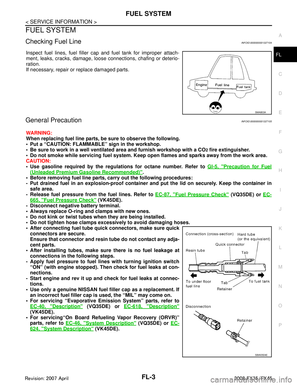
Checking Fuel LineINFOID:0000000001327104
Inspect fuel lines, fuel filler cap and fuel tank for improper attach-
ment, leaks, cracks, damage, loos
e connections, chafing or deterio-
ration.
If necessary, repair or replace damaged parts.
General PrecautionINFOID:0000000001327105
WARNING:
When replacing fuel line parts, be sure to observe the following.
• Put a “CAUTION: FLAMMABLE” sign in the workshop.
Be sure to work in a well ventila ted area and furnish workshop with a CO
2 fire extinguisher.
Do not smoke while servicing fuel system. Keep open flames and sparks away from the work area.
CAUTION:
Use gasoline required by the regulations for octane number. Refer to GI-5, "
Precaution for Fuel
(Unleaded Premium Gasoline Recommended)".
Before removing fuel line parts, carry out the following procedures:
- Put drained fuel in an explosion-proof containe r and put the lid on securely. Keep the container in
safe area.
- Release fuel pressure from th e fuel lines. Refer to EC-87, "
Fuel Pressure Check" (VQ35DE) or EC-
665, "Fuel Pressure Check" (VK45DE).
- Disconnect negative battery terminal.
Always replace O-ring and clamps with new ones.
Do not kink or twist tubes when they are being installed.
Do not tighten hose clamps excessi vely to avoid damaging hoses.
After connecting fuel tube qu ick connectors, make sure quick
connectors are secure.
Ensure that connector and resin tube do not contact any adja-
cent parts.
After installing tubes, make su re there is no fuel leakage at
connections in the following steps.
- Apply fuel pressure to fuel li nes with turning ignition switch
“ON” (with engine stopped). Th en check for fuel leaks at con-
nections.
- Start engine and rev it up and check for fuel leaks at connec- tions.
Use only a genuine NISSAN fuel filler cap as a replacement. If
an incorrect fuel filler cap is used, the “MIL” may come on.
For servicing “Evaporative Emi ssion System” parts, refer to
EC-40, "
Description" (VQ35DE) or EC-618, "Description"
(VK45DE).
For servicing“On Board Refueling Vapor Recovery (ORVR)”
parts, refer to EC-46, "
System Description" (VQ35DE) or EC-
624, "System Description" (VK45DE).
SMA803A
SBIA0504E
3AA93ABC3ACD3AC03ACA3AC03AC63AC53A913A773A893A873A873A8E3A773A983AC73AC93AC03AC3
3A893A873A873A8F3A773A9D3AAF3A8A3A8C3A863A9D3AAF3A8B3A8C
Page 2837 of 3924

FUEL LEVEL SENSOR UNIT, FUEL FILTER AND FUEL PUMP ASSEMBLY
FL-5
< SERVICE INFORMATION >
C
D E
F
G H
I
J
K L
M A
FL
NP
O
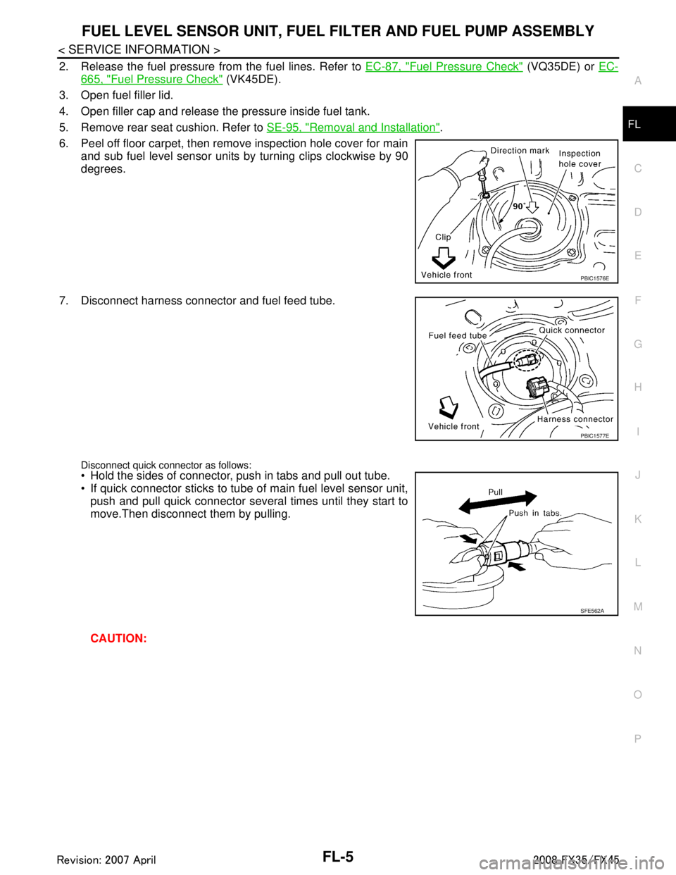
2. Release the fuel pressure from the fuel lines. Refer to
EC-87, "Fuel Pressure Check" (VQ35DE) or EC-
665, "Fuel Pressure Check" (VK45DE).
3. Open fuel filler lid.
4. Open filler cap and release the pressure inside fuel tank.
5. Remove rear seat cushion. Refer to SE-95, "
Removal and Installation".
6. Peel off floor carpet, then remove inspection hole cover for main and sub fuel level sensor units by turning clips clockwise by 90
degrees.
7. Disconnect harness connector and fuel feed tube.
Disconnect quick connector as follows: Hold the sides of connector, push in tabs and pull out tube.
If quick connector sticks to tube of main fuel level sensor unit, push and pull quick connector several times until they start to
move.Then disconnect them by pulling.
CAUTION:
PBIC1576E
PBIC1577E
SFE562A
3AA93ABC3ACD3AC03ACA3AC03AC63AC53A913A773A893A873A873A8E3A773A983AC73AC93AC03AC3
3A893A873A873A8F3A773A9D3AAF3A8A3A8C3A863A9D3AAF3A8B3A8C