2008 INFINITI FX35 center console
[x] Cancel search: center consolePage 2478 of 3924
FLOOR TRIMEI-41
< SERVICE INFORMATION >
C
DE
F
G H
J
K L
M A
B
EI
N
O P
FLOOR TRIM
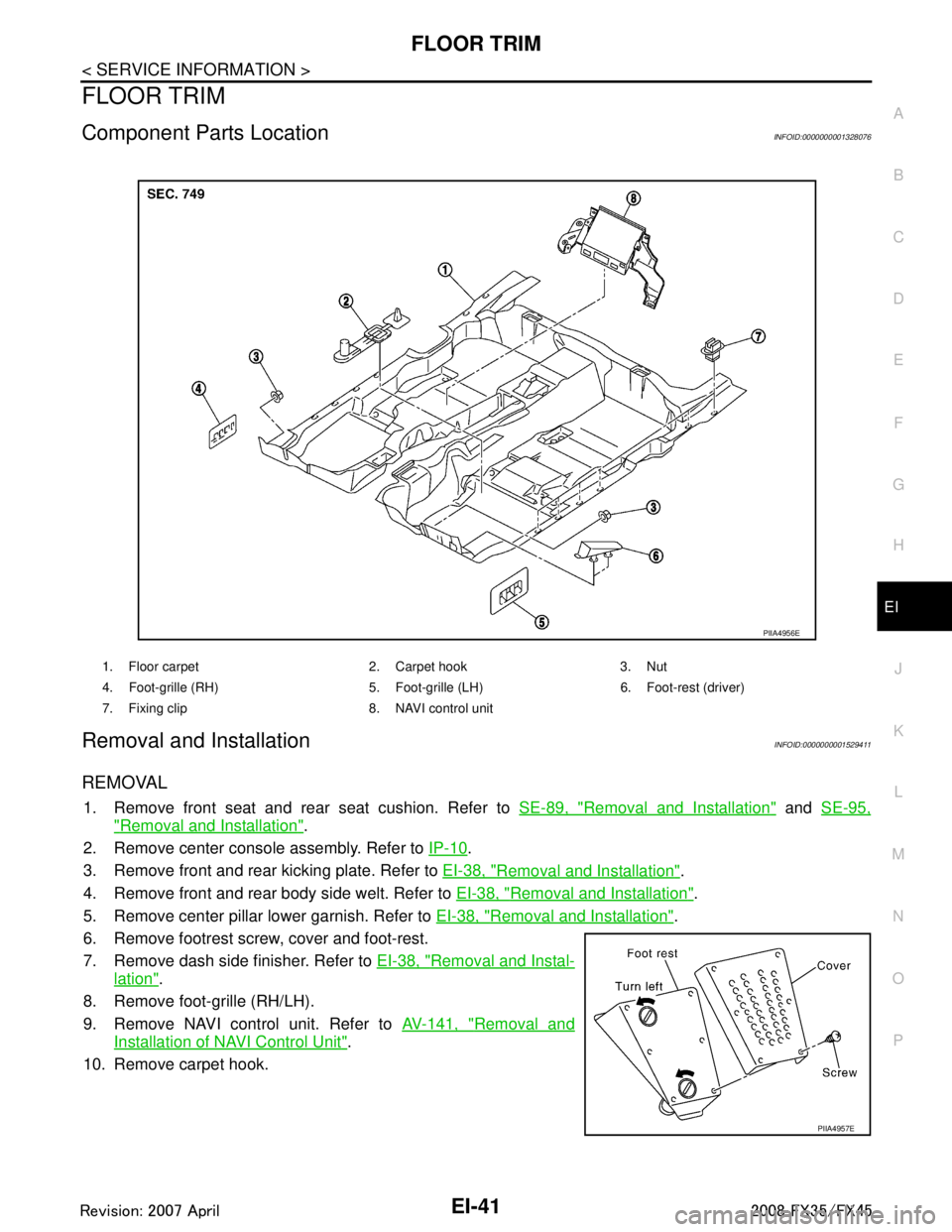
Component Parts LocationINFOID:0000000001328076
Removal and InstallationINFOID:0000000001529411
REMOVAL
1. Remove front seat and rear seat cushion. Refer to SE-89, "Removal and Installation" and SE-95,
"Removal and Installation".
2. Remove center console assembly. Refer to IP-10
.
3. Remove front and rear kicking plate. Refer to EI-38, "
Removal and Installation".
4. Remove front and rear body side welt. Refer to EI-38, "
Removal and Installation".
5. Remove center pillar lower garnish. Refer to EI-38, "
Removal and Installation".
6. Remove footrest screw, cover and foot-rest.
7. Remove dash side finisher. Refer to EI-38, "
Removal and Instal-
lation".
8. Remove foot-grille (RH/LH).
9. Remove NAVI control unit. Refer to AV-141, "
Removal and
Installation of NAVI Control Unit".
10. Remove carpet hook.
1. Floor carpet 2. Carpet hook 3. Nut
4. Foot-grille (RH) 5. Foot-gri lle (LH) 6. Foot-rest (driver)
7. Fixing clip 8. NAVI control unit
PIIA4956E
PIIA4957E
3AA93ABC3ACD3AC03ACA3AC03AC63AC53A913A773A893A873A873A8E3A773A983AC73AC93AC03AC3
3A893A873A873A8F3A773A9D3AAF3A8A3A8C3A863A9D3AAF3A8B3A8C
Page 2481 of 3924
EI-44
< SERVICE INFORMATION >
HEADLINING
Removal and Installation
INFOID:0000000001529412
REMOVAL
1. Remove front pillar garnish. Refer to EI-38, "Removal and Installation".
2. Remove kicking plate (front/rear). Refer to EI-38, "
Removal and Installation".
3. Remove body side welt. Refer to EI-38, "
Removal and Installation".
4. Remove seat belt shoulder anchor (front/rear). Refer to SB-3, "
Removal and Installation of Front Seat
Belt" and SB-5, "Removal and Installation of Rear Seat Belt".
5. Remove center pillar garnish (lower/upper) and luggage side finisher assembly and rear pillar upper gar- nish assembly. Refer to EI-38, "
Removal and Installation" and EI-46, "Removal and Installation".
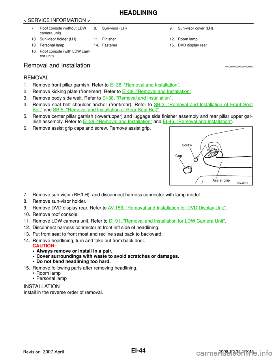
6. Remove assist grip caps and screw. Remove assist grip.
7. Remove sun-visor (RH/LH), and disconnect harness connector with lamp model.
8. Remove sun-visor holder.
9. Remove DVD display rear. Refer to AV-156, "
Removal and Installation for DVD Display Unit".
10. Remove roof console.
11. Remove LDW camera unit. Refer to DI-91, "
Removal and Installation for LDW Camera Unit".
12. Disconnect harness connector at front left side of headlining.
13. Put front seat to front most and recline seat back to backward.
14. Remove headlining, turn and take out from back door. CAUTION:
Always remove or install in a pair.
Cover surroundings with waste to avoid scratches or damages.
Do not bend headlining too hard.
15. Remove following parts after removing headlining. Room lamp
Personal lamp
INSTALLATION
Install in the reverse order of removal.
7. Roof console (without LDW
camera unit) 8. Sun-visor (LH) 9. Sun-visor cover (LH)
10. Sun-visor holder (LH) 11. Finisher 12. Room lamp
13. Personal lamp 14. Fastener 15. DVD display rear
16. Roof console (with LDW cam- era unit)
PIIA4952E
3AA93ABC3ACD3AC03ACA3AC03AC63AC53A913A773A893A873A873A8E3A773A983AC73AC93AC03AC3
3A893A873A873A8F3A773A9D3AAF3A8A3A8C3A863A9D3AAF3A8B3A8C
Page 2920 of 3924
SQUEAK AND RATTLE TROUBLE DIAGNOSESGW-7
< SERVICE INFORMATION >
C
DE
F
G H
J
K L
M A
B
GW
N
O P
Insulates where slight movement is present. Ideal for instrument panel applications.
SILICONE GREASE
Used in place of UHMW tape that will be visible or not fit.
Note: Will only last a few months.
SILICONE SPRAY
Use when grease cannot be applied.
DUCT TAPE
Use to eliminate movement.
CONFIRM THE REPAIR
Confirm that the cause of a noise is repaired by test driving the vehicle.Operate the vehicle under the same
conditions as when the noise originallyoccurred. Refer to the notes on the Diagnostic Worksheet.
Generic Squeak and Rattle TroubleshootingINFOID:0000000001327958
Refer to Table of Contents for specific component removal and installationinformation.
INSTRUMENT PANEL
Most incidents are caused by contact and movement between:
1. The cluster lid A and instrument panel
2. Acrylic lens and combination meter housing
3. Instrument panel to front pillar garnish
4. Instrument panel to windshield
5. Instrument panel mounting pins
6. Wiring harnesses behind the combination meter
7. A/C defroster duct and duct joint
These incidents can usually be located by tapping or moving the components to duplicate the noise or by
pressing on the components while driving to stop the noi se. Most of these incidents can be repaired by apply-
ing felt cloth tape or silicon spray (in hard to reach areas). Urethane pads can be used to insulate wiring har-
ness.
CAUTION:
Do not use silicone spray to isolat e a squeak or rattle. If you saturatet he area with silicone, you will not
be able to recheck the repair.
CENTER CONSOLE
Components to pay attention to include:
1. Shifter assembly cover to finisher
2. A/C control unit and cluster lid C
3. Wiring harnesses behind audio and A/C control unit
The instrument panel repair and isolation procedures also apply to thecenter console.
DOORS
Pay attention to the:
1. Finisher and inner panel making a slapping noise
2. Inside handle escutcheon to door finisher
3. Wiring harnesses tapping
4. Door striker out of alignment causing a popping noise on startsand stops
Tapping or moving the components or pressing on them while driving to duplicate the conditions can isolate
many of these incidents. You can usually insulate the ar eas with felt cloth tape or insulator foam blocks from
the Nissan Squeak and Rattle Kit (J43980) to repair the noise.
TRUNK
Trunk noises are often caused by a loose jack or loose items put intothe trunk by the owner.
In addition look for:
1. Trunk lid dumpers out of adjustment
2. Trunk lid striker out of adjustment
3. The trunk lid torsion bars knocking together
4. A loose license plate or bracket
3AA93ABC3ACD3AC03ACA3AC03AC63AC53A913A773A893A873A873A8E3A773A983AC73AC93AC03AC3
3A893A873A873A8F3A773A9D3AAF3A8A3A8C3A863A9D3AAF3A8B3A8C
Page 3007 of 3924
IP-6
< SERVICE INFORMATION >
SQUEAK AND RATTLE TROUBLE DIAGNOSES
Insulates where slight movement is present. Ideal for instrument panel applications.
SILICONE GREASE
Used in of UHMW tape that will be visible or not fit.
Note: Will only last a few months.
SILICONE SPRAY
Use when grease cannot be applied.
DUCT TAPE
Use to eliminate movement.
CONFIRM THE REPAIR
Confirm that the cause of a noise is repaired by test driving the vehicle. Operate the vehicle under the same
conditions as when the noise originally occurred. Refer to the notes on the Diagnostic Worksheet.
Generic Squeak and Rattle TroubleshootingINFOID:0000000001328085
Refer to Table of Contents for specific component removal and installation information.
INSTRUMENT PANEL
Most incidents are caused by contact and movement between:
1. The cluster lid A and instrument panel
2. Acrylic lens and combination meter housing
3. Instrument panel to front pillar garnish
4. Instrument panel to windshield
5. Instrument panel mounting pins
6. Wiring harnesses behind the combination meter
7. A/C defroster duct and duct joint
These incidents can usually be located by tapping or moving the components to duplicate the noise or by
pressing on the components while driving to stop the noi se. Most of these incidents can be repaired by apply-
ing felt cloth tape or silicon spray (in hard to reach areas). Urethane pads can be used to insulate wiring har-
ness.
CAUTION:
Do not use silicone spray to isolate a squeak or ra ttle. If you saturate the area with silicone, you will
not be able to recheck the repair.
CENTER CONSOLE
Components to pay attention to include:
1. Shifter assembly cover to finisher
2. A/C control unit and cluster lid C
3. Wiring harnesses behind audio and A/C control unit
The instrument panel repair and isolation pr ocedures also apply to the center console.
DOORS
Pay attention to the:
1. Finisher and inner panel making a slapping noise
2. Inside handle escutcheon to door finisher
3. Wiring harnesses tapping
4. Door striker out of alignment causing a popping noise on starts and stops
Tapping or moving the components or pressing on them wh ile driving to duplicate the conditions can isolate
many of these incidents. You can usually insulate the areas with felt cloth tape or insulator foam blocks from
the NISSAN Squeak and Rattle Kit (J43980) to repair the noise.
TRUNK
Trunk noises are often caused by a loose jack or loose items put into the trunk by the owner.
In addition look for:
1. Trunk lid dumpers out of adjustment
2. Trunk lid striker out of adjustment
3. The trunk lid torsion bars knocking together
4. A loose license plate or bracket
3AA93ABC3ACD3AC03ACA3AC03AC63AC53A913A773A893A873A873A8E3A773A983AC73AC93AC03AC3
3A893A873A873A8F3A773A9D3AAF3A8A3A8C3A863A9D3AAF3A8B3A8C
Page 3012 of 3924
INSTRUMENT PANEL ASSEMBLYIP-11
< SERVICE INFORMATION >
C
DE
F
G H
J
K L
M A
B
IP
N
O P
Removal and InstallationINFOID:0000000001328088
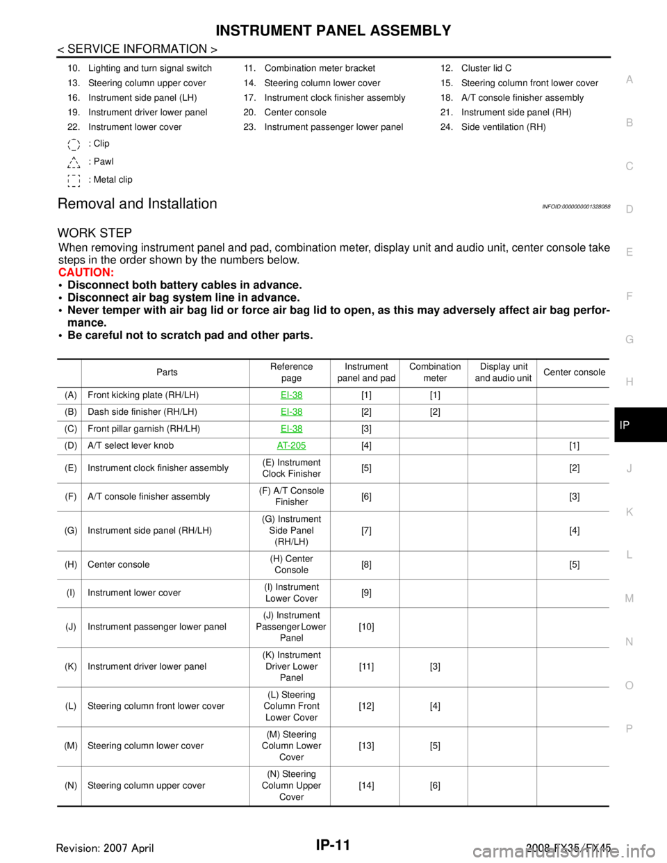
WORK STEP
When removing instrument panel and pad, combination me ter, display unit and audio unit, center console take
steps in the order shown by the numbers below.
CAUTION:
Disconnect both battery cables in advance.
Disconnect air bag system line in advance.
Never temper with air bag lid or force air bag lid to open, as this may adversely affect air bag perfor-
mance.
Be careful not to scratch pad and other parts.
10. Lighting and turn signal switch 11. Combination meter bracket 12. Cluster lid C
13. Steering column upper cover 14. Steering column lower cover 15. Steering column front lower cover
16. Instrument side panel (LH) 17. Instrument clock finisher assembly 18. A/T console finisher assembly
19. Instrument driver lower panel 20. Center console 21. Instrument side panel (RH)
22. Instrument lower cover 23. Instrument passenger lower panel 24. Side ventilation (RH)
: Clip
: Pawl
: Metal clip
Parts Reference
page Instrument
panel and pad Combination
meter Display unit
and audio unit Center console
(A) Front kicking plate (RH/LH) EI-38
[1] [1]
(B) Dash side finisher (RH/LH) EI-38
[2] [2]
(C) Front pillar garnish (RH/LH) EI-38
[3]
(D) A/T select lever knob AT- 2 0 5
[4] [1]
(E) Instrument clock finisher assembly (E) Instrument
Clock Finisher [5] [2]
(F) A/T console finisher assembly (F) A/T Console
Finisher [6] [3]
(G) Instrument side panel (RH/LH) (G) Instrument
Side Panel (RH/LH) [7] [4]
(H) Center console (H) Center
Console [8] [5]
(I) Instrument lower cover (I) Instrument
Lower Cover [9]
(J) Instrument passenger lower panel (J) Instrument
Passenger Lower
Panel [10]
(K) Instrument driver lower panel (K) Instrument
Driver Lower Panel [11] [3]
(L) Steering column front lower cover (L) Steering
Column Front Lower Cover [12] [4]
(M) Steering column lower cover (M) Steering
Column Lower
Cover [13] [5]
(N) Steering column upper cover (N) Steering
Column Upper Cover [14] [6]
3AA93ABC3ACD3AC03ACA3AC03AC63AC53A913A773A893A873A873A8E3A773A983AC73AC93AC03AC3
3A893A873A873A8F3A773A9D3AAF3A8A3A8C3A863A9D3AAF3A8B3A8C
Page 3013 of 3924
![INFINITI FX35 2008 Service Manual
IP-12
< SERVICE INFORMATION >
INSTRUMENT PANEL ASSEMBLY
[]: Number indicates step in removal procedures.
REMOVAL
(A) Front Kicking Plate (RH/LH)
Remove front kicking plate (RH/LH). Refer to EI-38.
(B INFINITI FX35 2008 Service Manual
IP-12
< SERVICE INFORMATION >
INSTRUMENT PANEL ASSEMBLY
[]: Number indicates step in removal procedures.
REMOVAL
(A) Front Kicking Plate (RH/LH)
Remove front kicking plate (RH/LH). Refer to EI-38.
(B](/manual-img/42/57017/w960_57017-3012.png)
IP-12
< SERVICE INFORMATION >
INSTRUMENT PANEL ASSEMBLY
[]: Number indicates step in removal procedures.
REMOVAL
(A) Front Kicking Plate (RH/LH)
Remove front kicking plate (RH/LH). Refer to EI-38.
(B) Dash Side Finisher (RH/LH)
1. Remove plastics nut.
2. Remove dash side finisher (RH/LH). Refer to EI-38
.
(C) Front Pillar Garnish (RH/LH)
Pull to inside of vehicle, disengage metal clips and remove front pillar garnish. Refer to EI-38.
(D) A/T Select Lever Knob
1. Pull down knob cover.
2. Remove lock-pin of select lever knob.
3. Lift up select lever knob and remove select lever knob.
Refer to AT-205, "
Control Device Removal and Installation".
(E) Instrument Clock Finisher
1. Remove screw and then pull back to your side of instrument
clock finisher.
2. Disconnect clips and harness connector, and remove instrument clock finisher.
(F) A/T Console Finisher
(O) Wiper and washer switch (O) Wiper and
Washer Switch [15] [7]
(P) Lighting and turn signal switch (P) Lighting and
Turn Signal Switch [16] [8]
(Q) Steering lock escutcheon (Q) Steering Lock
Escutcheon [17] [9]
(R) Combination meter assembly (R) Combination
Meter Assembly [18] [10]
(S) Cluster lid C (S) Cluster Lid C [19] [1] (T) Display unit and audio unit (T) Display Unit
and Audio Unit [20] [2]
(U) Front defroster grille (RH/LH) (U) Front
Defroster Grille (RH/LH) [21]
(V) Combination meter bracket (V) Combination
Meter Bracket [22]
(W) Side ventilation (RH/LH) (W) Side
Ventilation (RH/LH) [23]
(X) Instrument panel and pad (X) Instrument
Panel and Pad [24]
Parts
Reference
page Instrument
panel and pad Combination
meter Display unit
and audio unit Center console
: Clip
: Pawl
PIIB8535E
3AA93ABC3ACD3AC03ACA3AC03AC63AC53A913A773A893A873A873A8E3A773A983AC73AC93AC03AC3
3A893A873A873A8F3A773A9D3AAF3A8A3A8C3A863A9D3AAF3A8B3A8C
Page 3014 of 3924
INSTRUMENT PANEL ASSEMBLYIP-13
< SERVICE INFORMATION >
C
DE
F
G H
J
K L
M A
B
IP
N
O P
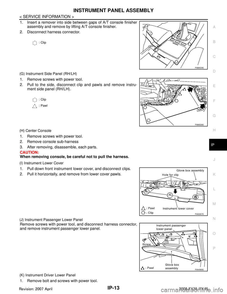
1. Insert a remover into side between gaps of A/T console finisher assembly and remove by lifting A/T console finisher.
2. Disconnect harness connector.
(G) Instrument Side Panel (RH/LH)
1. Remove screws with power tool.
2. Pull to the side, disconnect clip and pawls and remove instru- ment side panel (RH/LH).
(H) Center Console
1. Remove screws with power tool.
2. Remove console sub-harness
3. After removing, disassemble, each parts.
CAUTION:
When removing console, be car eful not to pull the harness.
(I) Instrument Lower Cover
1. Pull down front instrument lower cover, and disconnect clips.
2. Pull it horizontally, and remove from lower cover pawls.
(J) Instrument Passenger Lower Panel
Remove screws with power tool, and disconnect harness connector,
and remove instrument passenger lower panel.
(K) Instrument Driver Lower Panel
1. Remove bolt and screws with power tool.
: Clip
PIIB8534E
: Clip
: Pawl
PIIB8536E
PIIA5007E
PIIA4995E
3AA93ABC3ACD3AC03ACA3AC03AC63AC53A913A773A893A873A873A8E3A773A983AC73AC93AC03AC3
3A893A873A873A8F3A773A9D3AAF3A8A3A8C3A863A9D3AAF3A8B3A8C
Page 3018 of 3924
INSTRUMENT PANEL ASSEMBLYIP-17
< SERVICE INFORMATION >
C
DE
F
G H
J
K L
M A
B
IP
N
O P
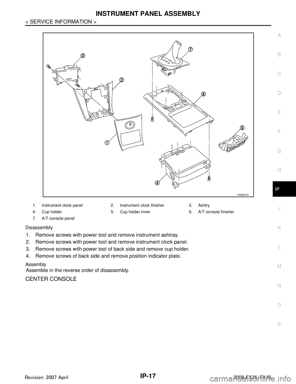
Disassembly
1. Remove screws with power tool and remove instrument ashtray.
2. Remove screws with power tool and remove instrument clock panel.
3. Remove screws with power tool of back side and remove cup holder.
4. Remove screws of back side and remove position indicator plate.
Assembly
Assemble in the reverse order of disassembly.
CENTER CONSOLE
1. Instrument clock panel 2. Instrument clock finisher 3. Ashtry
4. Cup holder 5. Cup holder inner 6. A/T console finisher
7. A/T console panel
PIIB8537E
3AA93ABC3ACD3AC03ACA3AC03AC63AC53A913A773A893A873A873A8E3A773A983AC73AC93AC03AC3
3A893A873A873A8F3A773A9D3AAF3A8A3A8C3A863A9D3AAF3A8B3A8C