2008 INFINITI FX35 brake rotor
[x] Cancel search: brake rotorPage 1010 of 3924

BR-26
< SERVICE INFORMATION >
REAR DISC BRAKE
CAUTION:
Refill with new brake fluid “DOT 3”.
Do not reuse drained brake fluid.
1. Install disc rotor.CAUTION:
Align the matching marks of disc rotor and wheel hub, which were marked at the time of removal
when reusing disc rotor.
2. Install caliper assembly to the vehicle, and tighten bolts to the specified torque. Refer to BR-24, "
Compo-
nent".
CAUTION:
Before installing caliper assembly to the vehicle , wipe off oil and grease on washer seats on axle
assembly and mounting surface of caliper assembly.
3. Install brake hose to caliper assembly and tighten union bolt to the specified torque. Refer to BR-24,
"Component".
CAUTION:
Do not reuse copper washer for union bolts.
Securely install brake hose to protrusion on caliper assembly.
4. After installing caliper assembly, refill with new brake fluid and bleed air. Refer to BR-8, "
Bleeding Brake
System".
5. Install tires to the vehicle.
Disassembly and Assembly of Brake Caliper AssemblyINFOID:0000000001327637
NOTE:
Do not remove torque member, brake pads, shims, shim cover and pad retainers, when disassembling or
assembling cylinder body.
DISASSEMBLY
1. Remove sliding pin bolts, and then remove brake pads, shims, shim cover, and pad retainer from torque
member and cylinder.
CAUTION:
Do not drop brake pads, shims, shim cover and pad retainer from torque member.
2. Remove sliding pin boot from torque member.
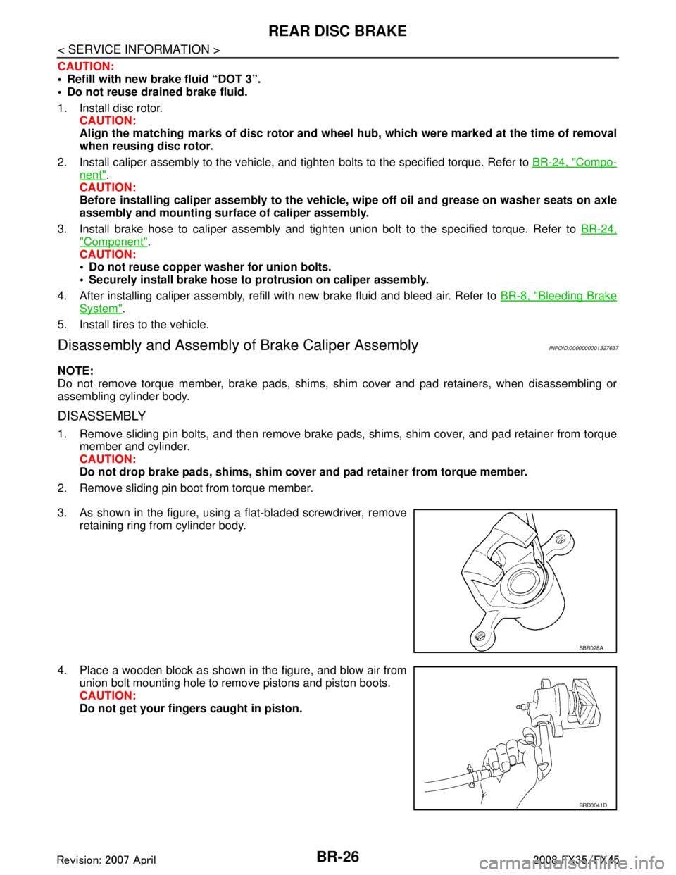
3. As shown in the figure, using a flat-bladed screwdriver, remove retaining ring from cylinder body.
4. Place a wooden block as shown in the figure, and blow air from union bolt mounting hole to remove pistons and piston boots.
CAUTION:
Do not get your fingers caught in piston.
SBR028A
BRD0041D
3AA93ABC3ACD3AC03ACA3AC03AC63AC53A913A773A893A873A873A8E3A773A983AC73AC93AC03AC3
3A893A873A873A8F3A773A9D3AAF3A8A3A8C3A863A9D3AAF3A8B3A8C
Page 1012 of 3924

BR-28
< SERVICE INFORMATION >
REAR DISC BRAKE
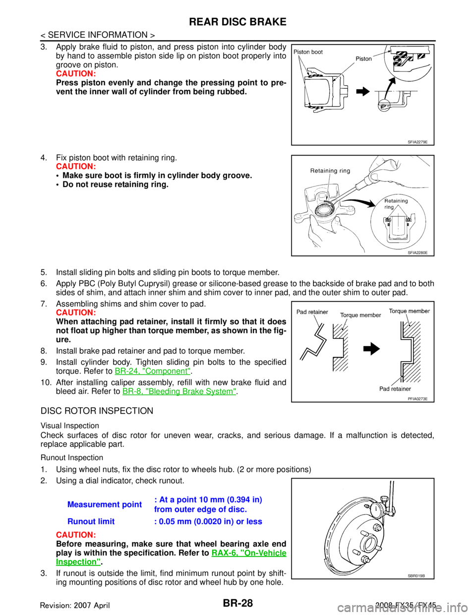
3. Apply brake fluid to piston, and press piston into cylinder bodyby hand to assemble piston side lip on piston boot properly into
groove on piston.
CAUTION:
Press piston evenly and change the pressing point to pre-
vent the inner wall of cylinder from being rubbed.
4. Fix piston boot with retaining ring. CAUTION:
Make sure boot is firmly in cylinder body groove.
Do not reuse retaining ring.
5. Install sliding pin bolts and sliding pin boots to torque member.
6. Apply PBC (Poly Butyl Cuprysil) grease or silicone- based grease to the backside of brake pad and to both
sides of shim, and attach inner shim and shim cover to inner pad, and the outer shim to outer pad.
7. Assembling shims and shim cover to pad. CAUTION:
When attaching pad retainer, inst all it firmly so that it does
not float up higher than torque member, as shown in the fig-
ure.
8. Install brake pad retainer and pad to torque member.
9. Install cylinder body. Tighten sliding pin bolts to the specified torque. Refer to BR-24, "
Component".
10. After installing caliper assembly, refill with new brake fluid and bleed air. Refer to BR-8, "
Bleeding Brake System".
DISC ROTOR INSPECTION
Visual Inspection
Check surfaces of disc rotor for uneven wear, cra cks, and serious damage. If a malfunction is detected,
replace applicable part.
Runout Inspection
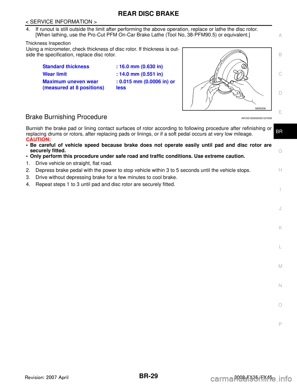
1. Using wheel nuts, fix the disc rotor to wheels hub. (2 or more positions)
2. Using a dial indicator, check runout.
CAUTION:
Before measuring, make sure that wheel bearing axle end
play is within the specification. Refer to RAX-6, "
On-Vehicle
Inspection".
3. If runout is outside the limit, find minimum runout point by shift- ing mounting positions of disc rotor and wheel hub by one hole.
SFIA2279E
SFIA2280E
PFIA0273E
Measurement point : At a point 10 mm (0.394 in)
from outer edge of disc.
Runout limit : 0.05 mm (0.0020 in) or less
SBR019B
3AA93ABC3ACD3AC03ACA3AC03AC63AC53A913A773A893A873A873A8E3A773A983AC73AC93AC03AC3
3A893A873A873A8F3A773A9D3AAF3A8A3A8C3A863A9D3AAF3A8B3A8C
Page 1013 of 3924

REAR DISC BRAKEBR-29
< SERVICE INFORMATION >
C
DE
G H
I
J
K L
M A
B
BR
N
O P
4. If runout is still outside the limit after performing the above operation, replace or lathe the disc rotor.
[When lathing, use the Pro-Cut PFM On-Car Br ake Lathe (Tool No, 38-PFM90.5) or equivalent.]
Thickness Inspection
Using a micrometer, check thickness of disc rotor. If thickness is out-
side the specification, replace disc rotor.
Brake Burnishing ProcedureINFOID:0000000001327638
Burnish the brake pad or lining contact surfaces of rotor according to following procedure after refinishing or
replacing drums or rotors, after replacing pads or li nings, or if a soft pedal occurs at very low mileage.
CAUTION:
Be careful of vehicle speed because brake does no t operate easily until pad and disc rotor are
securely fitted.
Only perform this procedure under safe road and traffic conditions. Use extreme caution.
1. Drive vehicle on straight, flat road.
2. Depress brake pedal with the power to stop vehicl e within 3 to 5 seconds until the vehicle stops.
3. Drive without depressing brake for a few minutes to cool brake.
4. Repeat steps 1 to 3 until pad and disc rotor are securely fitted. Standard thickness : 16.0 mm (0.630 in)
Wear limit : 14.0 mm (0.551 in)
Maximum uneven wear
(measured at 8 positions)
: 0.015 mm (0.0006 in) or
less
SBR020B
3AA93ABC3ACD3AC03ACA3AC03AC63AC53A913A773A893A873A873A8E3A773A983AC73AC93AC03AC3
3A893A873A873A8F3A773A9D3AAF3A8A3A8C3A863A9D3AAF3A8B3A8C
Page 1014 of 3924

BR-30
< SERVICE INFORMATION >
SERVICE DATA AND SPECIFICATIONS (SDS)
SERVICE DATA AND SPECIFICATIONS (SDS)
General SpecificationINFOID:0000000001327639
Unit: mm (in)
Brake PedalINFOID:0000000001327640
Brake BoosterINFOID:0000000001327641
Vacuum type
Check ValveINFOID:0000000001327642
Front Disc BrakeINFOID:0000000001327643
Rear Disc BrakeINFOID:0000000001327644
Front brakeRotor outer diameter
× thickness 320 × 34 (12.598 × 1.339)
Pad length × width × thickness 130.0 × 50.0 × 11.0 (5.118 × 1.969 × 0.433)
Cylinder bore diameter 45.0 (1.772) × 2
Rear brake Rotor outer diameter
× thickness 308 × 16 (12.13 × 0.63)
Pad length × width × thickness 83.0 × 33.0 × 8.5 (3.268 × 1.299 × 0.335)
Cylinder bore diameter 42.86 (1.6874)
Master cylinder Cylinder bore diameter 25.4 (1.00)
Control valve Valve model Electric brake force distribution
Brake booster Diaphragm diameter Primary 228.5 (9.0)
Secondary 203.0 (8.0)
Recommended brake fluid DOT 3
Brake pedal height (from dash lower panel top surface) 161.5 − 171.5 mm (6.358 − 6.752 in)
Depressed pedal height
[under a force of 490 N (50 kg, 110 lb) with engine running] More than 95 mm (3.74 in)
Clearance between stopper rubber and the threaded end of stop lamp
switch and ASCD cancel switch (or brake switch) 0.74
− 1.96 mm (0.0291 − 0.0772 in)
Pedal play 3 − 11 mm (0.12 − 0.43 in)
Output rod length 15.6 − 15.9 mm (0.614 − 0.626 in)
Input rod length 126.5 mm (4.98 in)
Vacuum leakage
[at a vacuum of –66.7 kPa (–500 mmHg, –19.69 inHg)]Within vacuum of 1.3 kPa (10 mmHg, 0.39 inHg) for 15
seconds
Brake padStandard thickness 11.0 mm (0.433 in)
Repair limit thickness 2.0 mm (0.079 in)
Disc rotor Standard thickness 34.0 mm (1.339 in)
Wear limit 32.0 mm (1.260 in)
Maximum uneven wear (measured at 8 positions) 0.015mm (0.0006 in) or less
Runout limit (with the disc rotor attached to the vehicle) 0.04 mm (0.0016 in) or less
Brake pad
Standard thickness 8.5 mm (0.335 in)
Repair limit thickness 2.0 mm (0.079 in)
3AA93ABC3ACD3AC03ACA3AC03AC63AC53A913A773A893A873A873A8E3A773A983AC73AC93AC03AC3
3A893A873A873A8F3A773A9D3AAF3A8A3A8C3A863A9D3AAF3A8B3A8C
Page 1021 of 3924
![INFINITI FX35 2008 Service Manual
BRC-6
< SERVICE INFORMATION >[VDC/TCS/ABS]
PRECAUTIONS
If the following components are replaced with non-genui
ne components or converted, VDC OFF indicator
lamp and SLIP indicator lamp may turn on INFINITI FX35 2008 Service Manual
BRC-6
< SERVICE INFORMATION >[VDC/TCS/ABS]
PRECAUTIONS
If the following components are replaced with non-genui
ne components or converted, VDC OFF indicator
lamp and SLIP indicator lamp may turn on](/manual-img/42/57017/w960_57017-1020.png)
BRC-6
< SERVICE INFORMATION >[VDC/TCS/ABS]
PRECAUTIONS
If the following components are replaced with non-genui
ne components or converted, VDC OFF indicator
lamp and SLIP indicator lamp may turn on or the VDC system may not operate properly. Components
related to suspension (shock absorber, strut, spring, bushing, etc.), Tires, wheels (exclude specified size),
components related to brake (pad, rotor, caliper, etc. ), components related to engine (muffler, ECM, etc.),
components related to body reinforcement (roll bar, tower bar, etc.).
Driving in the condition of breakage or excessive wear of suspension, tires or components related to the
brakes may cause VDC OFF indicator lamp and SLIP indicator lamp turn on, and the VDC system may not
operate properly.
When the TCS or VDC is activated by sudden accele ration or sudden turn, some noise may occur. The
noise is a result of the normal operation of the TCS and VDC.
When driving on roads which have extreme slopes (s uch as mountainous roads) or high banks (such as
sharp carves on a freeway), the VDC may not operate nor mally, or VDC OFF indicator lamp and SLIP indi-
cator lamp may turn on. However, this is not a malfunction, if normal operation can be resumed after restart-
ing engine.
Sudden turns (such as spin turns, acceleration turns) , drifting, etc. When VDC function is OFF (VDC OFF
SW ON) may cause the G sensor system indicate a malf unction. However, this is not a malfunction, if nor-
mal operation can be resumed after restarting engine.
Change 4 tires at a time. Be sure to use specified- size tires that have the same brand name and pattern.
Wheel sensor errors can be detected be self-diagnosis when tires have wide abrasion variations or the size
is different from the genuine tires.
3AA93ABC3ACD3AC03ACA3AC03AC63AC53A913A773A893A873A873A8E3A773A983AC73AC93AC03AC3
3A893A873A873A8F3A773A9D3AAF3A8A3A8C3A863A9D3AAF3A8B3A8C
Page 1022 of 3924
![INFINITI FX35 2008 Service Manual
PREPARATIONBRC-7
< SERVICE INFORMATION > [VDC/TCS/ABS]
C
D
E
G H
I
J
K L
M A
B
BRC
N
O P
PREPARATION
Special Service ToolINFOID:0000000001327656
The actual shapes of Kent-Moore tools may differ fr om INFINITI FX35 2008 Service Manual
PREPARATIONBRC-7
< SERVICE INFORMATION > [VDC/TCS/ABS]
C
D
E
G H
I
J
K L
M A
B
BRC
N
O P
PREPARATION
Special Service ToolINFOID:0000000001327656
The actual shapes of Kent-Moore tools may differ fr om](/manual-img/42/57017/w960_57017-1021.png)
PREPARATIONBRC-7
< SERVICE INFORMATION > [VDC/TCS/ABS]
C
D
E
G H
I
J
K L
M A
B
BRC
N
O P
PREPARATION
Special Service ToolINFOID:0000000001327656
The actual shapes of Kent-Moore tools may differ fr om those of special service tools illustrated here.
Commercial Service ToolINFOID:0000000001327657
Tool number
(Kent-Moore No.)
Tool name Description
ST30720000
(J-25405)
Drift
a: 77 mm (3.03 in) dia.
b: 55.5 mm (2.185 in) dia.
Installing rear sensor rotor
ST27863000
(—)
Drift
a: 74.5 mm (2.933 in) dia.
b: 62.5 mm (2.461 in) dia.
KV40104710
(—)
Drift
a: 76.3 mm (3.004 in) dia.
b: 67.9 mm (2.673 in) dia.
ZZA0701D
ZZA0832D
ZZA0832D
Tool name
Description
1: Flare nut crowfoot
a: 10 mm (0.39 in)/ 12 mm (0.47 in)
2: Torque wrench Installing brake tube
S-NT360
3AA93ABC3ACD3AC03ACA3AC03AC63AC53A913A773A893A873A873A8E3A773A983AC73AC93AC03AC3
3A893A873A873A8F3A773A9D3AAF3A8A3A8C3A863A9D3AAF3A8B3A8C
Page 1064 of 3924
![INFINITI FX35 2008 Service Manual
TROUBLE DIAGNOSIS FOR SYMPTOMSBRC-49
< SERVICE INFORMATION > [VDC/TCS/ABS]
C
D
E
G H
I
J
K L
M A
B
BRC
N
O P
TROUBLE DIAGNOSIS FOR SYMPTOMS
Excessive ABS Function Operation FrequencyINFOID:000000000 INFINITI FX35 2008 Service Manual
TROUBLE DIAGNOSIS FOR SYMPTOMSBRC-49
< SERVICE INFORMATION > [VDC/TCS/ABS]
C
D
E
G H
I
J
K L
M A
B
BRC
N
O P
TROUBLE DIAGNOSIS FOR SYMPTOMS
Excessive ABS Function Operation FrequencyINFOID:000000000](/manual-img/42/57017/w960_57017-1063.png)
TROUBLE DIAGNOSIS FOR SYMPTOMSBRC-49
< SERVICE INFORMATION > [VDC/TCS/ABS]
C
D
E
G H
I
J
K L
M A
B
BRC
N
O P
TROUBLE DIAGNOSIS FOR SYMPTOMS
Excessive ABS Function Operation FrequencyINFOID:0000000001327692
1.CHECK FRONT AND REAR AXLE
Make sure there is no excessive looseness in the front and rear axles.
OK or NG
OK >> GO TO 2.
NG >> Check front or rear axle system.
2.CHECK WHEEL SENSOR
Perform following inspection for wheel sensor:
Sensor mount and damage inspection
Sensor rotor mount and damage inspection
Sensor connector connection inspection
Sensor harness inspection
OK or NG
OK >> GO TO 3.
NG >> Replace sensor or sensor rotor.
3.CHECK ABS WARNING LAMP DISPLAY
Make sure warning lamp turns off approximately 2 seconds after the ignition switch is turned ON or when driv-
ing.
OK or NG
OK >> Normal
NG >> Perform self-diagnosis. Refer to BRC-26, "
Self-Diagnosis".
Unexpected Pedal ReactionINFOID:0000000001327693
1.CHECK BRAKE PEDAL STROKE
Check brake pedal stroke.
Is the stroke too long?
YES >> Bleed air from brake piping. Check brake pedal, brake booster, and master cylinder mount for play, looseness, and brakesystem for fluid leaks, etc. If any malfunctions are found, make repair.
NO >> GO TO 2.
2.CHECK FUNCTION
Disconnect ABS actuator and electric unit (control unit) c onnector E56 and make sure that braking force is suf-
ficient when ABS in not operating. After the inspection, reconnect connector.
OK or NG
OK >> CHECK WHEEL SENSOR. Refer to BRC-49, "Excessive ABS Function Operation Frequency".
NG >> Check brake system.
The Braking Distance Is LongINFOID:0000000001327694
CAUTION:
On slippery road surfaces, the st opping distance might be longer wi th the ABS operating than when
the ABS is not operating.
1.CHECK FUNCTION
Disconnect ABS actuator and electric unit (control unit) connector E56 to deactivate ABS. In this condition,
check stopping distance. After inspection, connect connector.
OK or NG
OK >> Bleed air from brake piping. Check brake system.
NG >> CHECK WHEEL SENSOR. Refer to BRC-49, "
Excessive ABS Function Operation Frequency".
3AA93ABC3ACD3AC03ACA3AC03AC63AC53A913A773A893A873A873A8E3A773A983AC73AC93AC03AC3
3A893A873A873A8F3A773A9D3AAF3A8A3A8C3A863A9D3AAF3A8B3A8C
Page 2769 of 3924
![INFINITI FX35 2008 Service Manual
FAX-4
< SERVICE INFORMATION >[2WD]
FRONT WHEEL HUB AND KNUCKLE
FRONT WHEEL HUB AND KNUCKLE
On-Vehicle InspectionINFOID:0000000001327506
Make sure the mounting conditions (looseness, back
lash) of ea INFINITI FX35 2008 Service Manual
FAX-4
< SERVICE INFORMATION >[2WD]
FRONT WHEEL HUB AND KNUCKLE
FRONT WHEEL HUB AND KNUCKLE
On-Vehicle InspectionINFOID:0000000001327506
Make sure the mounting conditions (looseness, back
lash) of ea](/manual-img/42/57017/w960_57017-2768.png)
FAX-4
< SERVICE INFORMATION >[2WD]
FRONT WHEEL HUB AND KNUCKLE
FRONT WHEEL HUB AND KNUCKLE
On-Vehicle InspectionINFOID:0000000001327506
Make sure the mounting conditions (looseness, back
lash) of each component and component status (wear,
damage) are normal.
WHEEL BEARING INSPECTION
Move wheel hub in the axial direction by hand. Che ck that there is no looseness of front wheel bearing.
Rotate wheel hub and make sure there is no unusual noi se or other irregular conditions. If there are any
irregular conditions, replace wheel hub and bearing assembly.
Removal and InstallationINFOID:0000000001327507
COMPONENTS
REMOVAL
1. Remove tires from vehicle with power tool.
2. Remove brake caliper with power tool. Hang it in a place where it will not interfere with work. Refer to BR-
18.
NOTE:
Avoid depressing brake pedal while brake caliper is removed.
3. Put alignment marks on disc rotor and wheel hub and bearing assembly, then remove disc rotor.
4. Remove wheel sensor from wheel hub and bearing assembly. Refer to BRC-52
.
CAUTION:
Do not pull on wheel sensor harness.
5. Remove cotter pin at steering outer socket, then loosen mount- ing nut.Axial end play : 0.05 mm (0.002 in) or less
1. Disc rotor 2. Wheel hub and bearing assembly 3. Splash guard
4. Steering knuckle 5. Cotter pin
Refer to
GI-8, "
Component", for the symbols in the figure.
PDIA1216E
SDIA1480E
3AA93ABC3ACD3AC03ACA3AC03AC63AC53A913A773A893A873A873A8E3A773A983AC73AC93AC03AC3
3A893A873A873A8F3A773A9D3AAF3A8A3A8C3A863A9D3AAF3A8B3A8C