2008 INFINITI FX35 window
[x] Cancel search: windowPage 2988 of 3924

REAR WINDOW DEFOGGERGW-75
< SERVICE INFORMATION >
C
DE
F
G H
J
K L
M A
B
GW
N
O P
Check Driver Side Door Mirror Defogger CircuitINFOID:0000000001328015
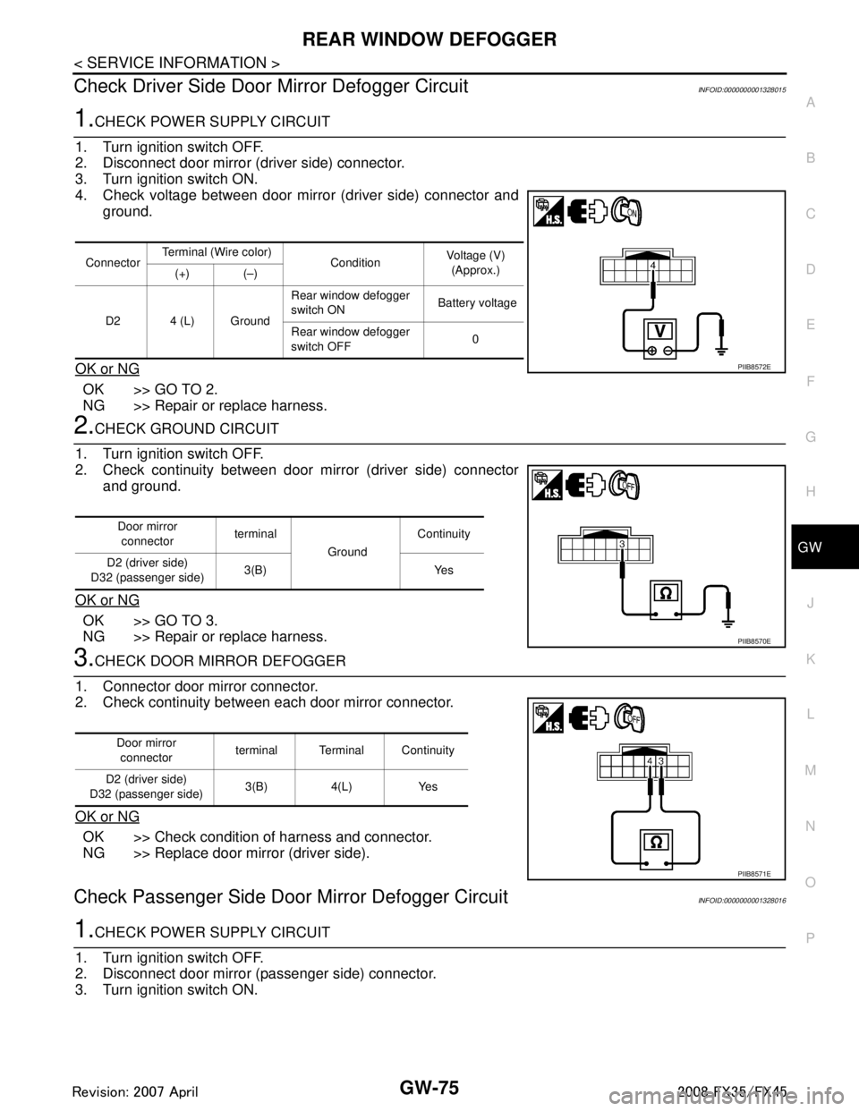
1.CHECK POWER SUPPLY CIRCUIT
1. Turn ignition switch OFF.
2. Disconnect door mirror (driver side) connector.
3. Turn ignition switch ON.
4. Check voltage between door mirror (driver side) connector and ground.
OK or NG
OK >> GO TO 2.
NG >> Repair or replace harness.
2.CHECK GROUND CIRCUIT
1. Turn ignition switch OFF.
2. Check continuity between door mirror (driver side) connector and ground.
OK or NG
OK >> GO TO 3.
NG >> Repair or replace harness.
3.CHECK DOOR MIRROR DEFOGGER
1. Connector door mirror connector.
2. Check continuity between each door mirror connector.
OK or NG
OK >> Check condition of harness and connector.
NG >> Replace door mirror (driver side).
Check Passenger Si de Door Mirror Defogger CircuitINFOID:0000000001328016
1.CHECK POWER SUPPLY CIRCUIT
1. Turn ignition switch OFF.
2. Disconnect door mirror (passenger side) connector.
3. Turn ignition switch ON.
Connector Terminal (Wire color)
ConditionVoltage (V)
(Approx.)
(+) (–)
D2 4 (L) Ground Rear window defogger
switch ON
Battery voltage
Rear window defogger
switch OFF 0
PIIB8572E
Door mirror
connector terminal
GroundContinuity
D2 (driver side)
D32 (passenger side) 3(B) Yes
PIIB8570E
Door mirror
connector terminal Terminal Continuity
D2 (driver side)
D32 (passenger side) 3(B) 4(L) Yes
PIIB8571E
3AA93ABC3ACD3AC03ACA3AC03AC63AC53A913A773A893A873A873A8E3A773A983AC73AC93AC03AC3
3A893A873A873A8F3A773A9D3AAF3A8A3A8C3A863A9D3AAF3A8B3A8C
Page 2989 of 3924

GW-76
< SERVICE INFORMATION >
REAR WINDOW DEFOGGER
4. Check voltage between door mirror (passenger side) connectorand ground.
OK or NG
OK >> GO TO 2.
NG >> Repair or replace harness.
2.CHECK GROUND CIRCUIT
1. Turn ignition switch OFF.
2. Check continuity between door mirror (passenger side) connec- tor and ground.
OK or NG
OK >> GO TO 3.
NG >> Repair or replace harness.
3.CHECK DOOR MIRROR DEFOGGER
1. Connector door mirror connector.
2. Check continuity between each door mirror connector.
OK or NG
OK >> Check condition of harness and connector.
NG >> Replace door mirror (passenger side).
Check Rear Windo w Defogger SignalINFOID:0000000001328017
1.CHECK REAR WINDOW DEFOGGER SWITCH LAMP
A/C and AV switch self-diagnosis is performed. Refer to AV-34, "
A/C and AV Switch Self-Diagnosis Function"
Does rear window defogger switch light?
YES >> GO TO 2.
NO >> Replace A/C and AV switch.
2.CHECK AV COMMUNICATION LINE
AV communication line check is performed. Refer to AV-79, "
Unable to Operate System with A/C and AV
Switch"
Is rear window defogger displayed on the display?
YES >> GO TO 3.
NO >> Replace display control unit.
3.CHECK CAN COMMUNICATION LINE
ConnectorTerminal (Wire color)
ConditionVoltage (V)
(Approx.)
(+) (–)
D32 4 (L) Ground Rear window defogger
switch ON
Battery voltage
Rear window defogger
switch OFF 0
PIIB8572E
Door mirror
connector terminal
GroundContinuity
D2 (driver side)
D32 (passenger side) 3(B) Yes
PIIB8570E
Door mirror
connector terminal Terminal Continuity
D2 (driver side)
D32 (passenger side) 3(B) 4(L) Yes
PIIB8571E
3AA93ABC3ACD3AC03ACA3AC03AC63AC53A913A773A893A873A873A8E3A773A983AC73AC93AC03AC3
3A893A873A873A8F3A773A9D3AAF3A8A3A8C3A863A9D3AAF3A8B3A8C
Page 2990 of 3924

REAR WINDOW DEFOGGERGW-77
< SERVICE INFORMATION >
C
DE
F
G H
J
K L
M A
B
GW
N
O P
CAN communication line check is performed. Refer to AV-79, "CAN Communication Check".
OK or NG
OK >> Check condition of harness and connector.
NG >> In addition, it is necessary to check CAN communication line. Refer to AV-79, "
CAN Communica-
tion Check".
Check FilamentINFOID:0000000001328018
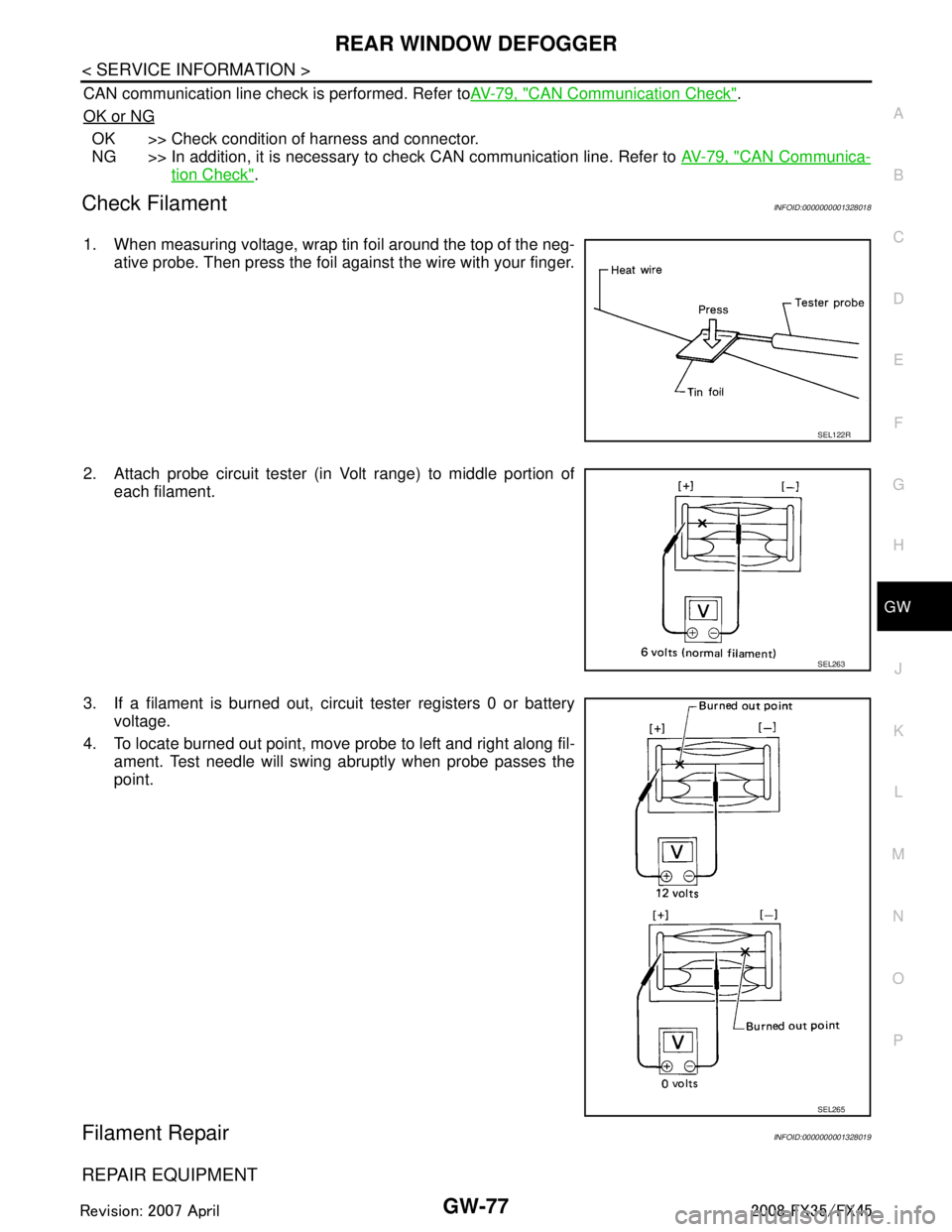
1. When measuring voltage, wrap tin foil around the top of the neg-
ative probe. Then press the foil against the wire with your finger.
2. Attach probe circuit tester (in Volt range) to middle portion of each filament.
3. If a filament is burned out, circuit tester registers 0 or battery voltage.
4. To locate burned out point, move probe to left and right along fil- ament. Test needle will swing abruptly when probe passes the
point.
Filament RepairINFOID:0000000001328019
REPAIR EQUIPMENT
SEL122R
SEL263
SEL265
3AA93ABC3ACD3AC03ACA3AC03AC63AC53A913A773A893A873A873A8E3A773A983AC73AC93AC03AC3
3A893A873A873A8F3A773A9D3AAF3A8A3A8C3A863A9D3AAF3A8B3A8C
Page 2991 of 3924

GW-78
< SERVICE INFORMATION >
REAR WINDOW DEFOGGER
Conductive silver composition (Dupont No. 4817 or equivalent)
Ruler 30 cm (11.8 in) long
Drawing pen
Heat gun
Alcohol
Cloth
REPAIRING PROCEDURE
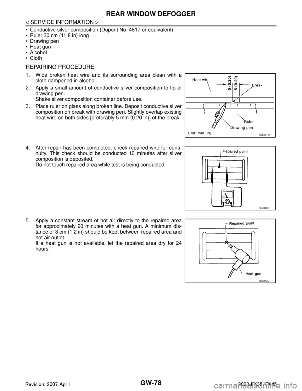
1. Wipe broken heat wire and its surrounding area clean with acloth dampened in alcohol.
2. Apply a small amount of conductive silver composition to tip of
drawing pen.
Shake silver composition container before use.
3. Place ruler on glass along broken line. Deposit conductive silver composition on break with drawing pen. Slightly overlap existing
heat wire on both sides [preferably 5 mm (0.20 in)] of the break.
4. After repair has been completed, check repaired wire for conti- nuity. This check should be conducted 10 minutes after silver
composition is deposited.
Do not touch repaired area while test is being conducted.
5. Apply a constant stream of hot air directly to the repaired area for approximately 20 minutes with a heat gun. A minimum dis-
tance of 3 cm (1.2 in) should be kept between repaired area and
hot air outlet.
If a heat gun is not available, let the repaired area dry for 24
hours.
PIIA0215E
SEL012D
SEL013D
3AA93ABC3ACD3AC03ACA3AC03AC63AC53A913A773A893A873A873A8E3A773A983AC73AC93AC03AC3
3A893A873A873A8F3A773A9D3AAF3A8A3A8C3A863A9D3AAF3A8B3A8C
Page 3065 of 3924
![INFINITI FX35 2008 Service Manual
TROUBLE DIAGNOSISLAN-45
< SERVICE INFORMATION > [CAN]
C
D
E
F
G H
I
J
L
M A
B
LAN
N
O P
Current gear position signal T R
Manual mode indicator signal T R
Output shaft revolution signal R T
P range si INFINITI FX35 2008 Service Manual
TROUBLE DIAGNOSISLAN-45
< SERVICE INFORMATION > [CAN]
C
D
E
F
G H
I
J
L
M A
B
LAN
N
O P
Current gear position signal T R
Manual mode indicator signal T R
Output shaft revolution signal R T
P range si](/manual-img/42/57017/w960_57017-3064.png)
TROUBLE DIAGNOSISLAN-45
< SERVICE INFORMATION > [CAN]
C
D
E
F
G H
I
J
L
M A
B
LAN
N
O P
Current gear position signal T R
Manual mode indicator signal T R
Output shaft revolution signal R T
P range signal T R R
Shift position indicator signal T R
Turbine revolution signal R T
A/C switch signal R T
Buzzer output signal TR
TR
Blower fan motor switch signal R T
Day time running light request signal T R
Door lock/unlock status signal T R
Door switch signal R T R R R R
Front fog light request signal T R
Front wiper request signal T R
High beam request signal T R R
Horn chirp signal T R
Ignition switch signal T R R
Key fob door unlock signal T R
Key fob ID signal T R
Key switch signal T R
Low beam request signal T R
Oil pressure switch signal RT
TR
Position light request signal T R R
Rear window defogger switch signal T R
Run flat tire warning lamp signal T R
Sleep wake up signal TRRR
RT
Theft warning horn request signal T R
Tire pressure warn ing lamp signal T R
Turn indicator signal T R
Alarm request signal R T
Back door open request signal R T
Door lock/unlock request signal R T
Ignition knob switch signal R T
Key warning signal T R
Power window open request signal R T
Steering angle sensor signal T R
Distance to empty signal R T
Fuel level low warning signal R T
Fuel level sensor signal R T
Manual mode shift down signal R T Signal name/Connecting unit
ECM
DISP TCM
BCM
I-KEY
STRG
M&AABS
ADP
IPDM-E
3AA93ABC3ACD3AC03ACA3AC03AC63AC53A913A773A893A873A873A8E3A773A983AC73AC93AC03AC3
3A893A873A873A8F3A773A9D3AAF3A8A3A8C3A863A9D3AAF3A8B3A8C
Page 3066 of 3924
![INFINITI FX35 2008 Service Manual
LAN-46
< SERVICE INFORMATION >[CAN]
TROUBLE DIAGNOSIS
NOTE:
CAN data of the air bag diagnosis sensor unit is not
used by usual service work, thus it is omitted.
TYPE 3
NOTE:
Refer to LAN-37, "
Abbre INFINITI FX35 2008 Service Manual
LAN-46
< SERVICE INFORMATION >[CAN]
TROUBLE DIAGNOSIS
NOTE:
CAN data of the air bag diagnosis sensor unit is not
used by usual service work, thus it is omitted.
TYPE 3
NOTE:
Refer to LAN-37, "
Abbre](/manual-img/42/57017/w960_57017-3065.png)
LAN-46
< SERVICE INFORMATION >[CAN]
TROUBLE DIAGNOSIS
NOTE:
CAN data of the air bag diagnosis sensor unit is not
used by usual service work, thus it is omitted.
TYPE 3
NOTE:
Refer to LAN-37, "
Abbreviation List" for the abbreviations of the connecting units.
T: Transmit R: Receive
Manual mode shift up signal R T
Manual mode signal R T
Not manual mode signal R T
Snow mode switch signal R T
Stop lamp switch signal R T
Turn LED burnout status signal R T
Vehicle speed signal RT
RRRRR T R
A/T shift schedule change demand signal R T
ABS operation signal T
ABS warning lamp signal RT
Brake warning lamp signal RT
SLIP indicator lamp signal RT
TCS operation signal T
VDC OFF indicator lamp signal R T
VDC OFF switch signal T
VDC operation signal T
Front wiper stop position signal R T
High beam status signal R T
Hood switch signal R T
Low beam status signal R T
Rear window defogger control signal R R T Signal name/Connecting unit
ECM
DISP TCM
BCM
I-KEY
STRG M&AABS
ADP
IPDM-E
Signal name/Connecting unitECM
DISP ICC
TCM
BCM
I-KEY
LANE
STRG M&AABS
LASER ADP
IPDM-E
A/C compressor feedback signal T R
A/C compressor request signal T R
Accelerator pedal position signal T R R R
ASCD OD cancel request signal T R
ASCD operation signal T R
Battery voltage signal T R
Closed throttle position signal T R R
Cooling fan speed request signal T R
Engine coolant temperature signal T R
Engine speed signal T R R R R R
Engine status signal T R
Fuel consumption monitor signal TR
RT
3AA93ABC3ACD3AC03ACA3AC03AC63AC53A913A773A893A873A873A8E3A773A983AC73AC93AC03AC3
3A893A873A873A8F3A773A9D3AAF3A8A3A8C3A863A9D3AAF3A8B3A8C
Page 3067 of 3924
![INFINITI FX35 2008 Service Manual
TROUBLE DIAGNOSISLAN-47
< SERVICE INFORMATION > [CAN]
C
D
E
F
G H
I
J
L
M A
B
LAN
N
O P
ICC steering switch signal T R
Malfunctioning indicator lamp signal T R
Snow mode switch signal RT
TR
Wide open INFINITI FX35 2008 Service Manual
TROUBLE DIAGNOSISLAN-47
< SERVICE INFORMATION > [CAN]
C
D
E
F
G H
I
J
L
M A
B
LAN
N
O P
ICC steering switch signal T R
Malfunctioning indicator lamp signal T R
Snow mode switch signal RT
TR
Wide open](/manual-img/42/57017/w960_57017-3066.png)
TROUBLE DIAGNOSISLAN-47
< SERVICE INFORMATION > [CAN]
C
D
E
F
G H
I
J
L
M A
B
LAN
N
O P
ICC steering switch signal T R
Malfunctioning indicator lamp signal T R
Snow mode switch signal RT
TR
Wide open throttle position signal T R
A/C switch/indicator signal TR
RT
System setting signal TR R
RT T
Buzzer output signal TR
TR
TR
ICC OD cancel request signal T R
ICC operation signal R T
ICC system display signal T R
ICC warning lamp signal T R
A/T CHECK indicator lamp signal T R
A/T self-diagnosis signal R T
Current gear position signal R T R
Manual mode indicator signal R T R
Output shaft revolution signal R R T R
P range signal R T R R
Shift position indicator signal R T R
Turbine revolution signal R R T
A/C switch signal R T
Blower fan motor switch signal R T
Day time running light request signal T R
Door lock/unlock status signal T R
Door switch signal R T R R R R
Front fog light request signal T R
Front wiper request signal R T R
High beam request signal T R R
Horn chirp signal T R
Ignition switch signal T R R
Key fob door unlock signal T R
Key fob ID signal T R
Key switch signal T R
Low beam request signal T R
Oil pressure switch signal RT
TR
Position light request signal T R R
Rear window defogger switch signal T R
Run flat tire warning lamp signal T R Signal name/Connecting unit
ECM
DISP ICC
TCM
BCM
I-KEY
LANE
STRG M&AABS
LASER ADP
IPDM-E
3AA93ABC3ACD3AC03ACA3AC03AC63AC53A913A773A893A873A873A8E3A773A983AC73AC93AC03AC3
3A893A873A873A8F3A773A9D3AAF3A8A3A8C3A863A9D3AAF3A8B3A8C
Page 3068 of 3924
![INFINITI FX35 2008 Service Manual
LAN-48
< SERVICE INFORMATION >[CAN]
TROUBLE DIAGNOSIS
NOTE:
Sleep wake up signalTRRR
RT
Theft warning horn request signal T R
Tire pressure warn ing lamp signal T R
Turn indicator signal T R R
Alarm INFINITI FX35 2008 Service Manual
LAN-48
< SERVICE INFORMATION >[CAN]
TROUBLE DIAGNOSIS
NOTE:
Sleep wake up signalTRRR
RT
Theft warning horn request signal T R
Tire pressure warn ing lamp signal T R
Turn indicator signal T R R
Alarm](/manual-img/42/57017/w960_57017-3067.png)
LAN-48
< SERVICE INFORMATION >[CAN]
TROUBLE DIAGNOSIS
NOTE:
Sleep wake up signalTRRR
RT
Theft warning horn request signal T R
Tire pressure warn ing lamp signal T R
Turn indicator signal T R R
Alarm request signal R T
Back door open request signal R T
Door lock/unlock request signal R T
Ignition knob switch signal R T
Key warning signal T R
Power window open request signal R T
Steering angle sensor signal T R
Distance to empty signal R T
Fuel level low warning signal R T
Fuel level sensor signal R T
Manual mode shift down signal R T
Manual mode shift up signal R T
Manual mode signal R T
Not manual mode signal R T
Parking brake switch signal R T
Stop lamp switch signal R T
Turn LED burnout status signal R T
Vehicle speed signal RRRT
RR RRR T RR
ICC sensor signal R T
A/T shift schedule change demand signal R T
ABS malfunction signal R T
ABS operation signal R T
ABS warning lamp signal RT
Brake warning lamp signal RT
SLIP indicator lamp signal RT
TCS malfunction signal R T
TCS operation signal R T
VDC malfunction signal R T
VDC OFF indicator lamp signal R T
VDC OFF switch signal R T
VDC operation signal R T
Front wiper stop position signal R T
High beam status signal R T
Hood switch signal R T
Low beam status signal R T
Rear window defogger control signal R R T
Signal name/Connecting unit
ECM
DISP ICC
TCM
BCM
I-KEY
LANE
STRG M&AABS
LASER ADP
IPDM-E
3AA93ABC3ACD3AC03ACA3AC03AC63AC53A913A773A893A873A873A8E3A773A983AC73AC93AC03AC3
3A893A873A873A8F3A773A9D3AAF3A8A3A8C3A863A9D3AAF3A8B3A8C