2008 INFINITI FX35 belt
[x] Cancel search: beltPage 3103 of 3924

LT-1
ELECTRICAL
C
DE
F
G H
I
J
L
M
SECTION LT
A
B
LT
N
O P
CONTENTS
LIGHTING SYSTEM
SERVICE INFORMATION .. ..........................4
PRECAUTIONS .............................................. .....4
Precaution for Supplemental Restraint System
(SRS) "AIR BAG" and "SEAT BELT PRE-TEN-
SIONER" ............................................................. ......
4
General Precaution for Service Operation ................4
HEADLAMP - XENON TYPE - ............................5
Component Parts and Harness Connector Loca-
tion ...................................................................... ......
5
System Description ...................................................5
CAN Communication System Description .................7
CAN Communication Unit .........................................7
Schematic .................................................................8
Wiring Diagram - H/LAMP - .......................................9
Terminal and Reference Value for BCM .................12
Terminal and Reference Value for IPDM E/R .........14
How to Proceed with Trouble Diagnosis .................14
Preliminary Check ...................................................15
CONSULT-III Functions (BCM) ...............................16
CONSULT-III Functions (IPDM E/R) .......................17
Headlamp Does Not Change To High Beam (Both
Sides) ......................................................................
18
Headlamp Does Not Change To High Beam (One
Side) ........................................................................
20
Headlamp Low Beam Does Not Illuminate (Both
Sides) .................................................................. ....
21
Headlamp Low Beam Does Not Illuminate (One
Side) .................................................................... ....
23
Headlamp RH Low Beam and High Beam Does
Not Illuminate ..........................................................
24
Headlamp LH Low Beam and High Beam Does
Not Illuminate ..........................................................
25
Headlamps Does Not Turn OFF .............................26
General Information for Xenon Headlamp Trouble
Diagnosis ................................................................
26
Caution: ...................................................................26
Xenon Headlamp Trouble Diagnosis ......................27
Aiming Adjustment ..................................................27
Bulb Replacement ...................................................28
Removal and Installation ..................................... ....30
Disassembly and Assembly .....................................30
DAYTIME LIGHT SYSTEM ...............................32
Component Parts and Harness Connector Loca-
tion ....................................................................... ....
32
System Description ..................................................32
CAN Communication System Description ...............33
CAN Communication Unit ........................................33
Schematic ................................................................34
Wiring Diagram - DTRL - .........................................35
Terminal and Reference Value for BCM ..................38
How to Proceed with Trouble Diagnosis ..................41
Preliminary Check ...................................................41
CONSULT-III Functions (BCM) ...............................43
Daytime Light Control Does Not Operate Properly ....44
Aiming Adjustment ...................................................46
Bulb Replacement ...................................................46
Removal and Installation .........................................46
Disassembly and Assembly .....................................46
AUTO LIGHT SYSTEM .....................................47
Component Parts and Harness Connector Loca-
tion ...........................................................................
47
System Description ..................................................47
CAN Communication System Description ...............48
CAN Communication Unit ........................................48
Major Component and Functions ............................48
Schematic ................................................................49
Wiring Diagram - AUTO/L - .....................................50
Terminal and Reference Value for BCM ..................52
Terminal and Reference Value for IPDM E/R ..........54
How to Proceed with Trouble Diagnosis ..................54
Preliminary Check ...................................................55
CONSULT-III Functions (BCM) ...............................56
CONSULT-III Functions (IPDM E/R) .......................57
Symptom Chart ........................................................58
Lighting Switch Inspection .......................................58
Optical sensor System Inspection ...........................59
Removal and Installation of Optical Sensor .............60
3AA93ABC3ACD3AC03ACA3AC03AC63AC53A913A773A893A873A873A8E3A773A983AC73AC93AC03AC3
3A893A873A873A8F3A773A9D3AAF3A8A3A8C3A863A9D3AAF3A8B3A8C
Page 3106 of 3924

LT-4
< SERVICE INFORMATION >
PRECAUTIONS
SERVICE INFORMATION
PRECAUTIONS
Precaution for Supplemental Restraint System (SRS) "AIR BAG" and "SEAT BELT
PRE-TENSIONER"
INFOID:0000000001612924
The Supplemental Restraint System such as “A IR BAG” and “SEAT BELT PRE-TENSIONER”, used along
with a front seat belt, helps to reduce the risk or severi ty of injury to the driver and front passenger for certain
types of collision. This system includes seat belt switch inputs and dual stage front air bag modules. The SRS
system uses the seat belt switches to determine the front air bag deployment, and may only deploy one front
air bag, depending on the severity of a collision and w hether the front occupants are belted or unbelted.
Information necessary to service the system safely is included in the “SUPPLEMENTAL RESTRAINT SYS-
TEM” and “SEAT BELTS” of this Service Manual.
WARNING:
• To avoid rendering the SRS inopera tive, which could increase the risk of personal injury or death in
the event of a collision which would result in air bag inflation, all maintenance must be performed by
an authorized NISS AN/INFINITI dealer.
Improper maintenance, including in correct removal and installation of the SRS, can lead to personal
injury caused by unintent ional activation of the system. For re moval of Spiral Cable and Air Bag
Module, see the “SUPPLEMEN TAL RESTRAINT SYSTEM”.
Do not use electrical test equipmen t on any circuit related to the SRS unless instructed to in this
Service Manual. SRS wiring harnesses can be identi fied by yellow and/or orange harnesses or har-
ness connectors.
General Precaution for Service OperationINFOID:0000000001328264
Never work with wet hands.
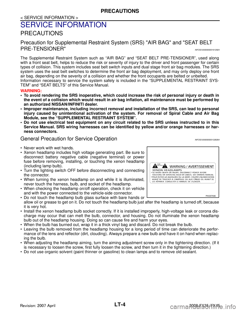
Xenon headlamp includes high voltage generating part. Be sure to disconnect battery negative cable (negative terminal) or power
fuse before removing, installing, or touching the xenon headlamp
(including lamp bulb).
Turn the lighting switch OFF before disconnecting and connecting the connector.
When turning the xenon headlamp on and while it is illuminated, never touch the harness, bulb, and socket of the headlamp.
When checking the headlamp on/off operation, check it on vehicle
and with the power connected to the vehicle-side connector.
Do not touch the headlamp bulb glass surface with bare hands or allow oil or grease to get on it. Do not touch the headl amp bulb just after the headlamp is turned off, because
it is very hot.
Install the xenon headlamp bulb socket co rrectly. If it is installed improperly, high-voltage leak or corona dis-
charge may occur that can melt the bulb, connecto r, and housing. Do not illuminate the xenon headlamp
bulb out of the headlamp housing. Doing so can cause fire and harm your eyes.
When the bulb has burned out, wrap it in a thick vinyl bag and discard. Do not break the bulb.
Leaving the bulb removed from the headlamp housing for a long period of time can deteriorate the perfor- mance of the lens and reflector (dirt, clouding). Al ways prepare a new bulb and have it on hand when replac-
ing the bulb.
When adjusting the headlamp aiming, turn the aiming adjus tment screw only in the tightening direction. (If it
is necessary to loosen the screw, first fully loosen the screw, and then turn it in the tightening direction.)
Do not use organic solvent (paint thinner or gasoline) to clean lamps and to remove old sealant.
PKID0793E
3AA93ABC3ACD3AC03ACA3AC03AC63AC53A913A773A893A873A873A8E3A773A983AC73AC93AC03AC3
3A893A873A873A8F3A773A9D3AAF3A8A3A8C3A863A9D3AAF3A8B3A8C
Page 3293 of 3924
![INFINITI FX35 2008 Service Manual
LU-8
< SERVICE INFORMATION >[VQ35DE]
OIL FILTER
OIL FILTER
Removal and InstallationINFOID:0000000001325815
REMOVAL
1. Remove front engine undercover with power tool.
2. Using oil filter wrench (SST), INFINITI FX35 2008 Service Manual
LU-8
< SERVICE INFORMATION >[VQ35DE]
OIL FILTER
OIL FILTER
Removal and InstallationINFOID:0000000001325815
REMOVAL
1. Remove front engine undercover with power tool.
2. Using oil filter wrench (SST),](/manual-img/42/57017/w960_57017-3292.png)
LU-8
< SERVICE INFORMATION >[VQ35DE]
OIL FILTER
OIL FILTER
Removal and InstallationINFOID:0000000001325815
REMOVAL
1. Remove front engine undercover with power tool.
2. Using oil filter wrench (SST), remove oil filter.
CAUTION:
Oil filter is provided with relief valve. Use Genuine NissanOil Filter or equivalent.
Be careful not to get burned when engine and engine oil may be hot.
When removing, prepare a sh op cloth to absorb any
engine oil leakage or spillage.
Do not allow engine oil to adhere to drive belts.
Completely wipe off any engine oil that adheres to engine
and vehicle.
INSTALLATION
1. Remove foreign materials adhering to oil filter installation surface.
2. Apply engine oil to the oil seal contact surface of new oil filter.
3. Screw oil filter manually until it touches the installation surface,
then tighten it by 2/3 turn. Or tighten to the specification.
INSPECTION AFTER INSTALLATION
1. Check the engine oil level. Refer to LU-5, "Inspection".
SBIA0454E
SBIA0455E
SMA010
Oil filter:
: 17.7 N·m (1.8 kg-m, 13 ft-lb)
SMA229B
3AA93ABC3ACD3AC03ACA3AC03AC63AC53A913A773A893A873A873A8E3A773A983AC73AC93AC03AC3
3A893A873A873A8F3A773A9D3AAF3A8A3A8C3A863A9D3AAF3A8B3A8C
Page 3295 of 3924
![INFINITI FX35 2008 Service Manual
LU-10
< SERVICE INFORMATION >[VQ35DE]
OIL FILTER BRACKET (AWD)
OIL FILTER BRACKET (AWD)
ComponentINFOID:0000000001325816
Removal and InstallationINFOID:0000000001325817
REMOVAL
WARNING:
Be careful no INFINITI FX35 2008 Service Manual
LU-10
< SERVICE INFORMATION >[VQ35DE]
OIL FILTER BRACKET (AWD)
OIL FILTER BRACKET (AWD)
ComponentINFOID:0000000001325816
Removal and InstallationINFOID:0000000001325817
REMOVAL
WARNING:
Be careful no](/manual-img/42/57017/w960_57017-3294.png)
LU-10
< SERVICE INFORMATION >[VQ35DE]
OIL FILTER BRACKET (AWD)
OIL FILTER BRACKET (AWD)
ComponentINFOID:0000000001325816
Removal and InstallationINFOID:0000000001325817
REMOVAL
WARNING:
Be careful not to get burn yourself, as engine oil may be hot.
1. Remove front engine undercover with power tool.
2. Using the oil filter wrench [SST: KV10115801 (J38956)], remove oil filter. Refer to
LU-8, "
Removal and
Installation".
CAUTION:
Do not spill engine oil on drive belt.
3. Remove oil cooler connector bolt, and then oil cooler with water hoses connected.
4. Disconnect oil temperature sensor and oi l pressure switch harness connectors.
5. Remove oil filter bracket from oil pan (upper).
6. Remove oil temperature sensor and oil pr essure switch from oil filter bracket.
INSTALLATION
Note the following, and install in the reverse order of removal.
Install oil pressure switch and oil temperature sensor as follows:
- Remove old liquid gasket adhering to oil pressure switch and oil filter bracket.
- Apply liquid gasket and install oil pressure switch, and then oil temperature sensor with a new washer.
Use Genuine RTV Silicone Seal ant or equivalent. Refer to GI-44, "
Recommended Chemical Product
and Sealant".
1. Oil filter 2. Connector bolt 3. Oil cooler
4. O-ring 5. Relief valve 6. Oil filter bracket
7. Gasket 8. Oil pressure switch 9. Oil temperature sensor
10. Washer 11. Oil pan (upper)
SBIA0593E
3AA93ABC3ACD3AC03ACA3AC03AC63AC53A913A773A893A873A873A8E3A773A983AC73AC93AC03AC3
3A893A873A873A8F3A773A9D3AAF3A8A3A8C3A863A9D3AAF3A8B3A8C
Page 3298 of 3924
![INFINITI FX35 2008 Service Manual
OIL COOLERLU-13
< SERVICE INFORMATION > [VQ35DE]
C
D
E
F
G H
I
J
K L
M A
LU
NP
O
AWD models
Removal and InstallationINFOID:0000000001325819
REMOVAL
WARNING:
Be careful not to get burn yourself, as en INFINITI FX35 2008 Service Manual
OIL COOLERLU-13
< SERVICE INFORMATION > [VQ35DE]
C
D
E
F
G H
I
J
K L
M A
LU
NP
O
AWD models
Removal and InstallationINFOID:0000000001325819
REMOVAL
WARNING:
Be careful not to get burn yourself, as en](/manual-img/42/57017/w960_57017-3297.png)
OIL COOLERLU-13
< SERVICE INFORMATION > [VQ35DE]
C
D
E
F
G H
I
J
K L
M A
LU
NP
O
AWD models
Removal and InstallationINFOID:0000000001325819
REMOVAL
WARNING:
Be careful not to get burn yourself, as en
gine oil and engine coolant may be hot.
NOTE:
When removing oil cooler only, step 2 is unnecessary.
1. Remove front engine undercover with power tool.
2. Drain engine coolant from radiator and cylinder block. Refer to CO-10, "
Changing Engine Coolant" and
EM-123, "
Disassembly and Assembly".
NOTE:
Perform this step when removing water pipes.
3. Disconnect water hoses from oil cooler. When removing oil cooler only, pinching water hoses near oil cooler to prevent engine coolant from spill-
ing out.
Remaining engine coolant in piping will come out. Use a tray to collect it.
CAUTION:
Perform this step when the engine is cold.
Do not spill engine coolant on drive belts.
4. Using oil filter wrench [SST: KV10115801 (J38956)], remove oil filter. Refer to LU-8, "
Removal and Instal-
lation".
CAUTION:
Do not spill engine oil on drive belts.
5. Remove connector bolt, and remove oil cooler. CAUTION:
Do not spill engine oil to rubber parts such as drive belts and engine mounting insulator.
SBIA0584E
1. Oil filter 2. Connector bolt 3. Oil cooler
4. O-ring 5. Relief valve 6. Oil filter bracket
7. Water hose 8. Water hose 9. Water pipe
10. Water hose
3AA93ABC3ACD3AC03ACA3AC03AC63AC53A913A773A893A873A873A8E3A773A983AC73AC93AC03AC3
3A893A873A873A8F3A773A9D3AAF3A8A3A8C3A863A9D3AAF3A8B3A8C
Page 3311 of 3924
![INFINITI FX35 2008 Service Manual
LU-26
< SERVICE INFORMATION >[VK45DE]
OIL FILTER
OIL FILTER
Removal and InstallationINFOID:0000000001325831
REMOVAL
1. Remove front engine undercover with power tool.
2. Using the oil filter wrench ( INFINITI FX35 2008 Service Manual
LU-26
< SERVICE INFORMATION >[VK45DE]
OIL FILTER
OIL FILTER
Removal and InstallationINFOID:0000000001325831
REMOVAL
1. Remove front engine undercover with power tool.
2. Using the oil filter wrench (](/manual-img/42/57017/w960_57017-3310.png)
LU-26
< SERVICE INFORMATION >[VK45DE]
OIL FILTER
OIL FILTER
Removal and InstallationINFOID:0000000001325831
REMOVAL
1. Remove front engine undercover with power tool.
2. Using the oil filter wrench (SST), remove the oil filter.
CAUTION:
Oil filter is provided with relief valve. Use Genuine NissanOil Filter or equivalent.
Be careful not to get burned when engine and engine oil may be hot.
When removing, prepare a sh op cloth to absorb any
engine oil leakage or spillage.
Do not allow engine oil to adhere to drive belts.
Completely wipe off any engine oil that adhere to engine
and vehicle.
INSTALLATION
1. Remove foreign materials adhering to oil filter installation surface.
2. Apply new engine oil to the oil seal circumference of the new oil filter.
3. Screw oil filter manually until it touches the installation surface,
then tighten it by 2/3 turn. Or tighten to specification.
INSPECTION AFTER INSTALLATION
1. Check the engine oil level. Refer to LU-23, "Inspection".
2. Start engine, and check there is no leaks of engine oil.
3. Stop engine and wait for 15 minutes.
4. Check the engine oil level and adjust engine oil. Refer to LU-23, "
Inspection".
PBIC1525E
SMA010
Oil filter:
:17.7 N·m (1.8 kg-m, 13 ft-lb)
SMA229B
3AA93ABC3ACD3AC03ACA3AC03AC63AC53A913A773A893A873A873A8E3A773A983AC73AC93AC03AC3
3A893A873A873A8F3A773A9D3AAF3A8A3A8C3A863A9D3AAF3A8B3A8C
Page 3312 of 3924
![INFINITI FX35 2008 Service Manual
OIL COOLERLU-27
< SERVICE INFORMATION > [VK45DE]
C
D
E
F
G H
I
J
K L
M A
LU
NP
O
OIL COOLER
ComponentINFOID:0000000001325832
Removal and InstallationINFOID:0000000001325833
WARNING:
Be careful not to INFINITI FX35 2008 Service Manual
OIL COOLERLU-27
< SERVICE INFORMATION > [VK45DE]
C
D
E
F
G H
I
J
K L
M A
LU
NP
O
OIL COOLER
ComponentINFOID:0000000001325832
Removal and InstallationINFOID:0000000001325833
WARNING:
Be careful not to](/manual-img/42/57017/w960_57017-3311.png)
OIL COOLERLU-27
< SERVICE INFORMATION > [VK45DE]
C
D
E
F
G H
I
J
K L
M A
LU
NP
O
OIL COOLER
ComponentINFOID:0000000001325832
Removal and InstallationINFOID:0000000001325833
WARNING:
Be careful not to get burn yourself, as
engine oil and engine coolant are hot.
REMOVAL
NOTE:
When removing oil cooler only, step 2 is unnecessary.
1. Remove front engine undercover with power tool.
2. Drain engine coolant from radiator and cylinder block. Refer to CO-37, "
Changing Engine Coolant" and
EM-241, "
Component".
NOTE:
Perform this step when removing water pipe.
3. Remove oil filter. Refer to LU-26, "
Removal and Installation".
CAUTION:
Do not spill engine oil on drive belts.
4. Disconnect water hoses from oil cooler. When removing oil cooler only, pinching water hoses near oil cooler to prevent engine coolant spilling.
CAUTION:
Perform this step when engine is cold.
Do not spill engine coolant on the drive belt.
5. Remove connector bolt, and remove oil cooler. CAUTION:
Do not spill engine oil to rubber parts such as drive belts and engine mounting insulator.
1. Oil filter 2. Connector bolt 3. Water hose
4. Water pipe 5. Oil cooler 6. O-ring
7. Oil pan (left side) 8. Water hose 9. Relief valve
PBIC2977E
3AA93ABC3ACD3AC03ACA3AC03AC63AC53A913A773A893A873A873A8E3A773A983AC73AC93AC03AC3
3A893A873A873A8F3A773A9D3AAF3A8A3A8C3A863A9D3AAF3A8B3A8C
Page 3318 of 3924

MA-1
MAINTENANCE
C
DE
F
G H
I
J
K
M
SECTION MA
A
B
MA
N
O P
CONTENTS
MAINTENANCE
SERVICE INFORMATION .. ..........................2
PREPARATION .............................................. .....2
Special Service Tool ........................................... ......2
Commercial Service Tool ..........................................2
GENERAL MAINTENANCE ................................3
Explanation of General Maintenance .................. ......3
PERIODIC MAINTENANCE ................................5
Introduction of Periodic Maintenance .................. ......5
Schedule 1 ................................................................5
Schedule 2 ................................................................7
RECOMMENDED FLUIDS AND LUBRI-
CANTS .................................................................
9
Fluids and Lubricants .......................................... ......9
Engine Oil Recommendation ....................................9
Anti-Freeze Coolant Mixture Ratio ..........................10
ENGINE MAINTENANCE (VQ35DE ENGINE) ....11
Checking Drive Belts ........................................... ....11
Drive Belts Tension Adjustment ..............................11
Changing Engine Coolant .......................................12
Checking Fuel Line .................................................15
Changing Air Cleaner Filter .....................................15
Changing Engine Oil ...............................................15
Changing Oil Filter ..................................................16
Changing Spark Plugs (Platinum-Tipped Type) ......17
Checking EVAP Vapor Line ....................................18
ENGINE MAINTENANCE (VK45DE ENGINE) ....19
Checking Drive Belts ........................................... ....19
Tension Adjustment ................................................19
Changing Engine Coolant .......................................19
Checking Fuel Line .............................................. ....22
Changing Air Cleaner Filter .....................................22
Changing Engine Oil ................................................22
Changing Oil Filter ...................................................23
Changing Spark Plugs (Platinum-Tipped Type) ......24
Checking EVAP Vapor Line .....................................25
CHASSIS AND BODY MAINTENANCE ...........26
Checking Exhaust System ................................... ....26
Checking A/T Fluid ..................................................26
Changing A/T Fluid ..................................................27
Checking Transfer Fluid ..........................................28
Changing Transfer Fluid ..........................................28
Checking Propeller Shaft .........................................29
Checking Differential Gear Oil .................................29
Changing Differential Gear Oil .................................29
Balancing Wheels (Bonding Weight Type) ..............30
Tire Rotation ............................................................31
Checking Brake Fluid Level and Leaks ...................32
Checking Brake Line and Cables ............................32
Changing Brake Fluid ..............................................32
Checking Disc Brake ...............................................32
Checking Steering Gear and Linkage ......................33
Checking Power Steering Fluid and Line ................33
Axle and Suspension Parts .....................................34
Drive Shaft ...............................................................34
Lubricating Locks, Hinges and Hood Latch .............35
Checking Seat Belt, Buckles, Retractors, Anchors
and Adjusters ...........................................................
35
SERVICE DATA AND SPECIFICATIONS
(SDS) .................................................................
37
Standard and Limit ..................................................37
3AA93ABC3ACD3AC03ACA3AC03AC63AC53A913A773A893A873A873A8E3A773A983AC73AC93AC03AC3
3A893A873A873A8F3A773A9D3AAF3A8A3A8C3A863A9D3AAF3A8B3A8C