2008 INFINITI FX35 ignition
[x] Cancel search: ignitionPage 3161 of 3924
AUTO LIGHT SYSTEMLT-59
< SERVICE INFORMATION >
C
DE
F
G H
I
J
L
M A
B
LT
N
O P
Optical sensor System InspectionINFOID:0000000001381750
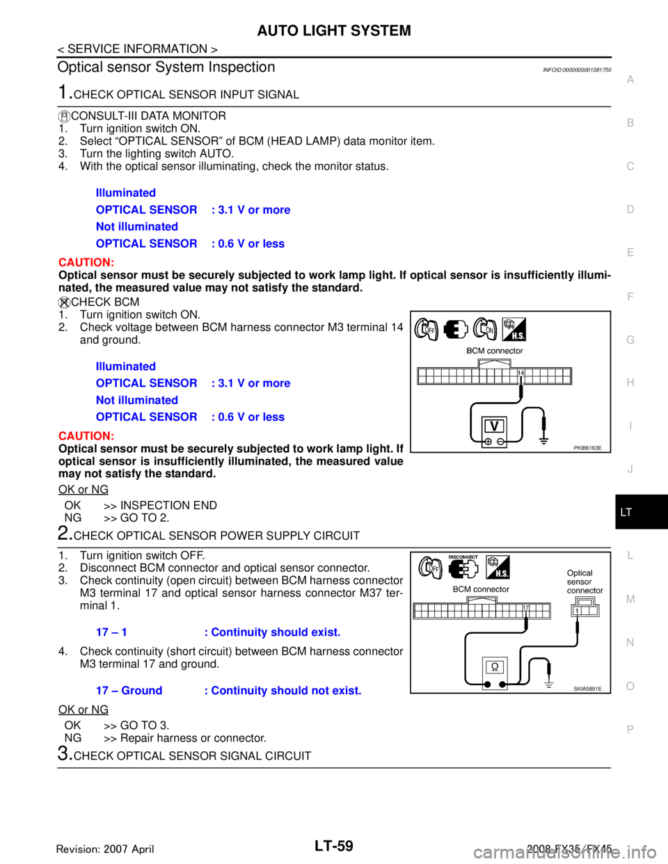
1.CHECK OPTICAL SENSOR INPUT SIGNAL
CONSULT-III DATA MONITOR
1. Turn ignition switch ON.
2. Select “OPTICAL SENSOR” of BC M (HEAD LAMP) data monitor item.
3. Turn the lighting switch AUTO.
4. With the optical sensor illuminat ing, check the monitor status.
CAUTION:
Optical sensor must be securely subject ed to work lamp light. If optical sensor is insufficiently illumi-
nated, the measured value may not satisfy the standard.
CHECK BCM
1. Turn ignition switch ON.
2. Check voltage between BCM harness connector M3 terminal 14
and ground.
CAUTION:
Optical sensor must be securely su bjected to work lamp light. If
optical sensor is insufficiently illuminated, the measured value
may not satisfy the standard.
OK or NG
OK >> INSPECTION END
NG >> GO TO 2.
2.CHECK OPTICAL SENSOR POWER SUPPLY CIRCUIT
1. Turn ignition switch OFF.
2. Disconnect BCM connector and optical sensor connector.
3. Check continuity (open circuit) between BCM harness connector M3 terminal 17 and optical sensor harness connector M37 ter-
minal 1.
4. Check continuity (short circuit) between BCM harness connector M3 terminal 17 and ground.
OK or NG
OK >> GO TO 3.
NG >> Repair harness or connector.
3.CHECK OPTICAL SENS OR SIGNAL CIRCUIT
Illuminated
OPTICAL SENSOR : 3.1 V or more
Not illuminated
OPTICAL SENSOR : 0.6 V or less
Illuminated
OPTICAL SENSOR : 3.1 V or more
Not illuminated
OPTICAL SENSOR : 0.6 V or less
PKIB6163E
17 – 1 : Continui
ty should exist.
17 – Ground : Continuity should not exist.
SKIA5891E
3AA93ABC3ACD3AC03ACA3AC03AC63AC53A913A773A893A873A873A8E3A773A983AC73AC93AC03AC3
3A893A873A873A8F3A773A9D3AAF3A8A3A8C3A863A9D3AAF3A8B3A8C
Page 3162 of 3924
LT-60
< SERVICE INFORMATION >
AUTO LIGHT SYSTEM
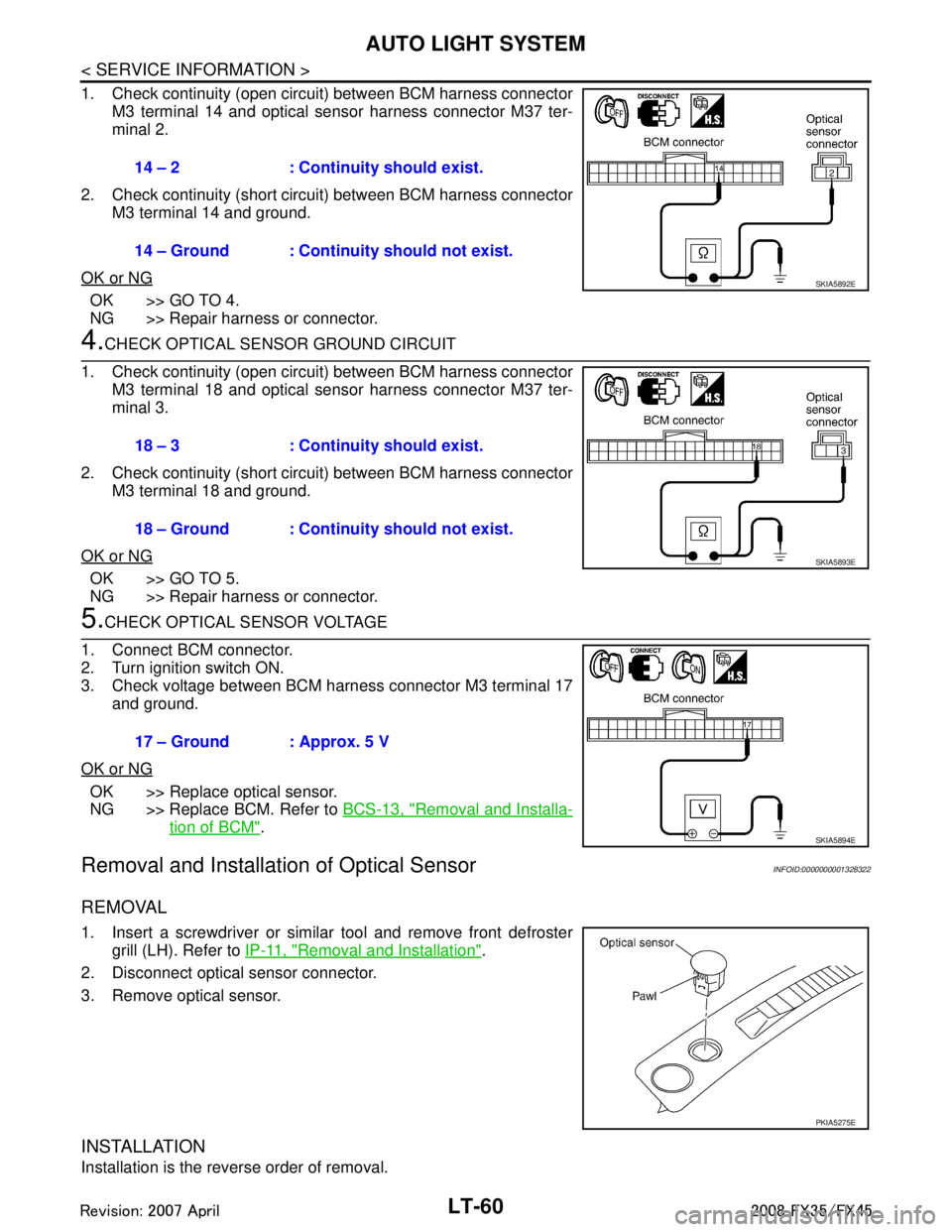
1. Check continuity (open circuit) between BCM harness connectorM3 terminal 14 and optical sensor harness connector M37 ter-
minal 2.
2. Check continuity (short circuit) between BCM harness connector M3 terminal 14 and ground.
OK or NG
OK >> GO TO 4.
NG >> Repair harness or connector.
4.CHECK OPTICAL SENSOR GROUND CIRCUIT
1. Check continuity (open circuit) between BCM harness connector M3 terminal 18 and optical sensor harness connector M37 ter-
minal 3.
2. Check continuity (short circuit) between BCM harness connector M3 terminal 18 and ground.
OK or NG
OK >> GO TO 5.
NG >> Repair harness or connector.
5.CHECK OPTICAL SENSOR VOLTAGE
1. Connect BCM connector.
2. Turn ignition switch ON.
3. Check voltage between BCM harness connector M3 terminal 17 and ground.
OK or NG
OK >> Replace optical sensor.
NG >> Replace BCM. Refer to BCS-13, "
Removal and Installa-
tion of BCM".
Removal and Installation of Optical SensorINFOID:0000000001328322
REMOVAL
1. Insert a screwdriver or similar tool and remove front defroster
grill (LH). Refer to IP-11, "
Removal and Installation".
2. Disconnect optical sensor connector.
3. Remove optical sensor.
INSTALLATION
Installation is the reverse order of removal. 14 – 2 : Continuity should exist.
14 – Ground : Continuity should not exist.
SKIA5892E
18 – 3 : Continuity should exist.
18 – Ground : Continuity should not exist.
SKIA5893E
17 – Ground : Approx. 5 V
SKIA5894E
PKIA5275E
3AA93ABC3ACD3AC03ACA3AC03AC63AC53A913A773A893A873A873A8E3A773A983AC73AC93AC03AC3
3A893A873A873A8F3A773A9D3AAF3A8A3A8C3A863A9D3AAF3A8B3A8C
Page 3168 of 3924
LT-66
< SERVICE INFORMATION >
FRONT FOG LAMP
FRONT FOG LAMP
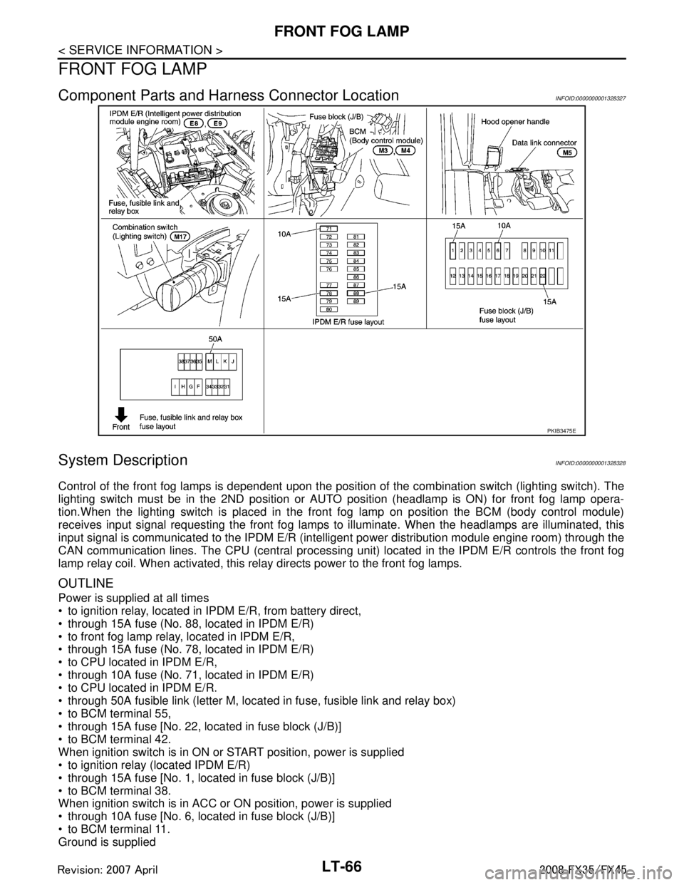
Component Parts and Harness Connector LocationINFOID:0000000001328327
System DescriptionINFOID:0000000001328328
Control of the front fog lamps is dependent upon the position of the combination switch (lighting switch). The
lighting switch must be in the 2ND position or AUTO position (headlamp is ON) for front fog lamp opera-
tion.When the lighting switch is placed in the front fog lamp on position the BCM (body control module)
receives input signal requesting the front fog lamps to illuminate. When the headlamps are illuminated, this
input signal is communicated to the IPDM E/R (inte lligent power distribution module engine room) through the
CAN communication lines. The CPU (central processing unit) located in the IPDM E/R controls the front fog
lamp relay coil. When activated, this relay directs power to the front fog lamps.
OUTLINE
Power is supplied at all times
to ignition relay, located in IP DM E/R, from battery direct,
through 15A fuse (No. 88, located in IPDM E/R)
to front fog lamp relay, located in IPDM E/R,
through 15A fuse (No. 78, located in IPDM E/R)
to CPU located in IPDM E/R,
through 10A fuse (No. 71, located in IPDM E/R)
to CPU located in IPDM E/R.
through 50A fusible link (letter M, located in fuse, fusible link and relay box)
to BCM terminal 55,
through 15A fuse [No. 22, located in fuse block (J/B)]
to BCM terminal 42.
When ignition switch is in ON or START position, power is supplied
to ignition relay (located IPDM E/R)
through 15A fuse [No. 1, located in fuse block (J/B)]
to BCM terminal 38.
When ignition switch is in ACC or ON position, power is supplied
through 10A fuse [No. 6, located in fuse block (J/B)]
to BCM terminal 11.
Ground is supplied
PKIB3475E
3AA93ABC3ACD3AC03ACA3AC03AC63AC53A913A773A893A873A873A8E3A773A983AC73AC93AC03AC3
3A893A873A873A8F3A773A9D3AAF3A8A3A8C3A863A9D3AAF3A8B3A8C
Page 3169 of 3924

FRONT FOG LAMPLT-67
< SERVICE INFORMATION >
C
DE
F
G H
I
J
L
M A
B
LT
N
O P
to BCM terminals 49 and 52
through grounds M35, M45 and M85,
to IPDM E/R terminals 38 and 60
through grounds E21, E50 and E51.
FRONT FOG LAMP OPERATION
The front fog lamp switch is built into combination s witch. The lighting switch must be in the 2ND position or
AUTO position (headlamp is ON) and the front fog lamp switch must be ON for front fog lamp operation.
With the front fog lamp switch in the ON position, t he CPU located in the IPDM E/R grounds the coil side of the
front fog lamp relay. The front fog lamp relay then directs power
through IPDM E/R terminal 36
to front fog lamp RH terminal 1,
through IPDM E/R terminal 37
to front fog lamp LH terminal 1.
Ground is supplied
to front fog lamp RH and LH terminals 2
through grounds E21, E50 and E51.
With power and grounds supplied, front fog lamps illuminate.
COMBINATION SWITCH READING FUNCTION
Refer to BCS-4, "System Description".
EXTERIOR LAMP BATTERY SAVER CONTROL
When the combination switch (lighting switch) is in the 2ND position (ON), the front fog lamp switch is ON, and
the ignition switch is turned from ON or ACC to OF F, the battery saver control feature is activated.
Under this condition, the front fog lamps (and headlamps ) remain illuminated for 5 minutes, then the front fog
lamps (and headlamps) are turned off.
Exterior lamp battery saver control mode can be changed by the function setting of CONSULT-III.
CAN Communication System DescriptionINFOID:0000000001328329
CAN (Controller Area Network) is a serial communication li ne for real time application. It is an on-vehicle mul-
tiplex communication line with high data communication speed and excellent error detection ability. Many elec-
tronic control units are equipped onto a vehicle, and each control unit shares information and links with other
control units during operation (not independent). In CAN communication, control units are connected with 2
communication lines (CAN H line, CAN L line) allowing a high rate of information transmission with less wiring.
Each control unit transmits/receives data but selectively reads required data only.
CAN Communication UnitINFOID:0000000001328330
Refer to LAN-43, "CAN System Specification Chart".
3AA93ABC3ACD3AC03ACA3AC03AC63AC53A913A773A893A873A873A8E3A773A983AC73AC93AC03AC3
3A893A873A873A8F3A773A9D3AAF3A8A3A8C3A863A9D3AAF3A8B3A8C
Page 3172 of 3924
LT-70
< SERVICE INFORMATION >
FRONT FOG LAMP
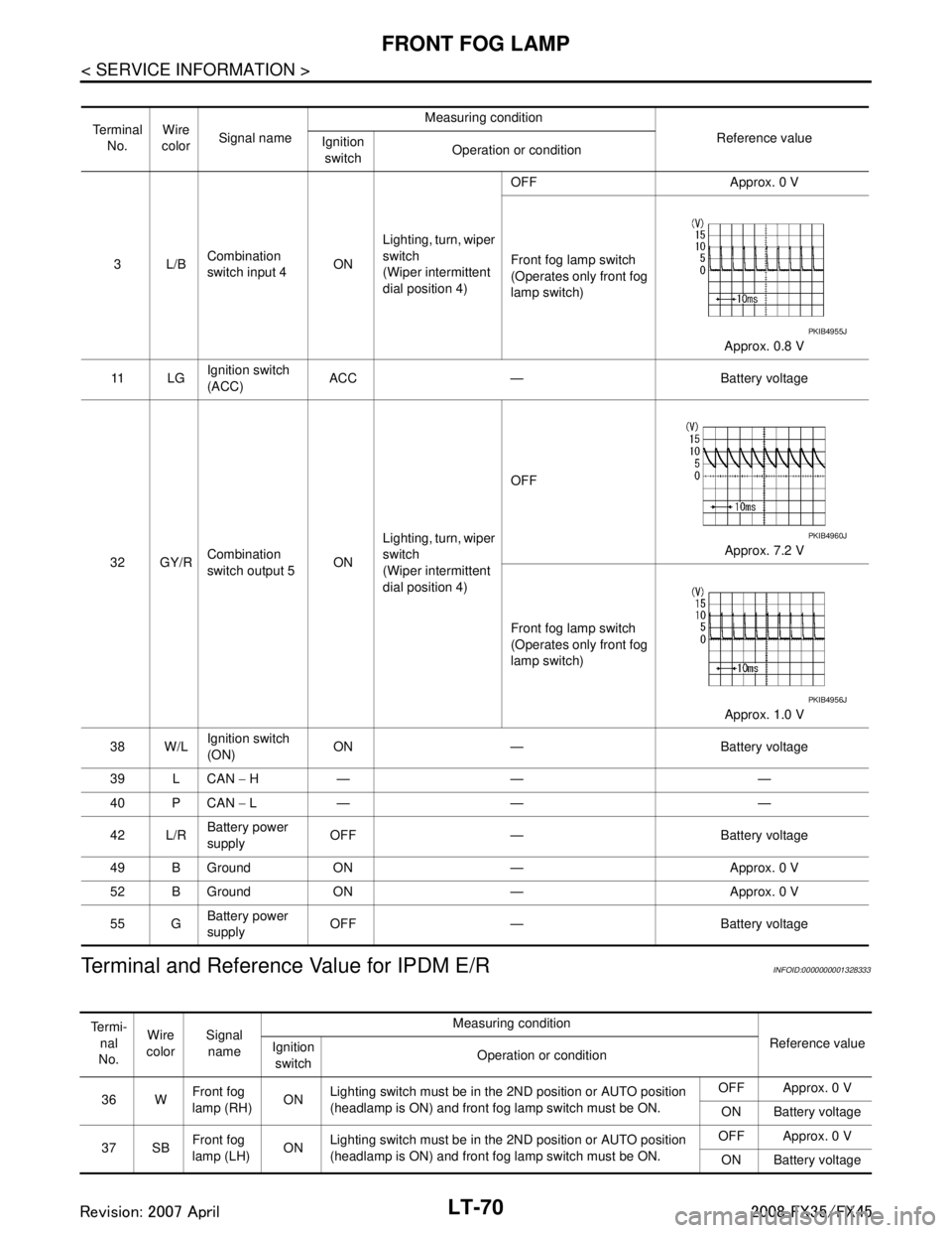
Terminal and Reference Value for IPDM E/R
INFOID:0000000001328333
Te r m i n a l No. Wire
color Signal name Measuring condition
Reference value
Ignition
switch Operation or condition
3L/B Combination
switch input 4
ONLighting, turn, wiper
switch
(Wiper intermittent
dial position 4) OFF Approx. 0 V
Front fog lamp switch
(Operates only front fog
lamp switch)
Approx. 0.8 V
11 L G Ignition switch
(ACC)
ACC — Battery voltage
32 GY/R Combination
switch output 5 ONLighting, turn, wiper
switch
(Wiper intermittent
dial position 4) OFF
Approx. 7.2 V
Front fog lamp switch
(Operates only front fog
lamp switch) Approx. 1.0 V
38 W/L Ignition switch
(ON)
ON — Battery voltage
39 L CAN − H— — —
40 P CAN − L— — —
42 L/R Battery power
supply OFF — Battery voltage
49 B Ground ON — Approx. 0 V
52 B Ground ON — Approx. 0 V
55 G Battery power
supply OFF — Battery voltage
PKIB4955J
PKIB4960J
PKIB4956J
Te r m i -
nal
No. Wire
color Signal
name Measuring condition
Reference value
Ignition
switch Operation or condition
36 W Front fog
lamp (RH)
ONLighting switch must be in the 2ND position or AUTO position
(headlamp is ON) and front fog lamp switch must be ON. OFF Approx. 0 V
ON Battery voltage
37 SB Front fog
lamp (LH)
ONLighting switch must be in the 2ND position or AUTO position
(headlamp is ON) and front fog lamp switch must be ON. OFF Approx. 0 V
ON Battery voltage
3AA93ABC3ACD3AC03ACA3AC03AC63AC53A913A773A893A873A873A8E3A773A983AC73AC93AC03AC3
3A893A873A873A8F3A773A9D3AAF3A8A3A8C3A863A9D3AAF3A8B3A8C
Page 3173 of 3924
FRONT FOG LAMPLT-71
< SERVICE INFORMATION >
C
DE
F
G H
I
J
L
M A
B
LT
N
O P
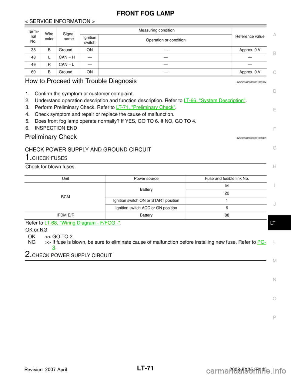
How to Proceed with Trouble DiagnosisINFOID:0000000001328334
1. Confirm the symptom or customer complaint.
2. Understand operation description and function description. Refer to LT-66, "
System Description".
3. Perform Preliminary Check. Refer to LT-71, "
Preliminary Check".
4. Check symptom and repair or replace the cause of malfunction.
5. Does front fog lamp operate normally? If YES, GO TO 6. If NO, GO TO 4.
6. INSPECTION END
Preliminary CheckINFOID:0000000001328335
CHECK POWER SUPPLY AND GROUND CIRCUIT
1.CHECK FUSES
Check for blown fuses.
Refer to LT-68, "
Wiring Diagram - F/FOG -".
OK or NG
OK >> GO TO 2.
NG >> If fuse is blown, be sure to eliminate caus e of malfunction before installing new fuse. Refer to PG-
3.
2.CHECK POWER SUPPLY CIRCUIT
38 B Ground ON — Approx. 0 V
48 L CAN − H— — —
49 R CAN − L— — —
60 B Ground ON — Approx. 0 V
Te r m i -
nal
No. Wire
color Signal
name Measuring condition
Reference value
Ignition
switch Operation or condition
Unit Power source Fuse and fusible link No.
BCM Battery
M
22
Ignition switch ON or START position 1 Ignition switch ACC or ON position 6
IPDM E/R Battery 88
3AA93ABC3ACD3AC03ACA3AC03AC63AC53A913A773A893A873A873A8E3A773A983AC73AC93AC03AC3
3A893A873A873A8F3A773A9D3AAF3A8A3A8C3A863A9D3AAF3A8B3A8C
Page 3174 of 3924
LT-72
< SERVICE INFORMATION >
FRONT FOG LAMP
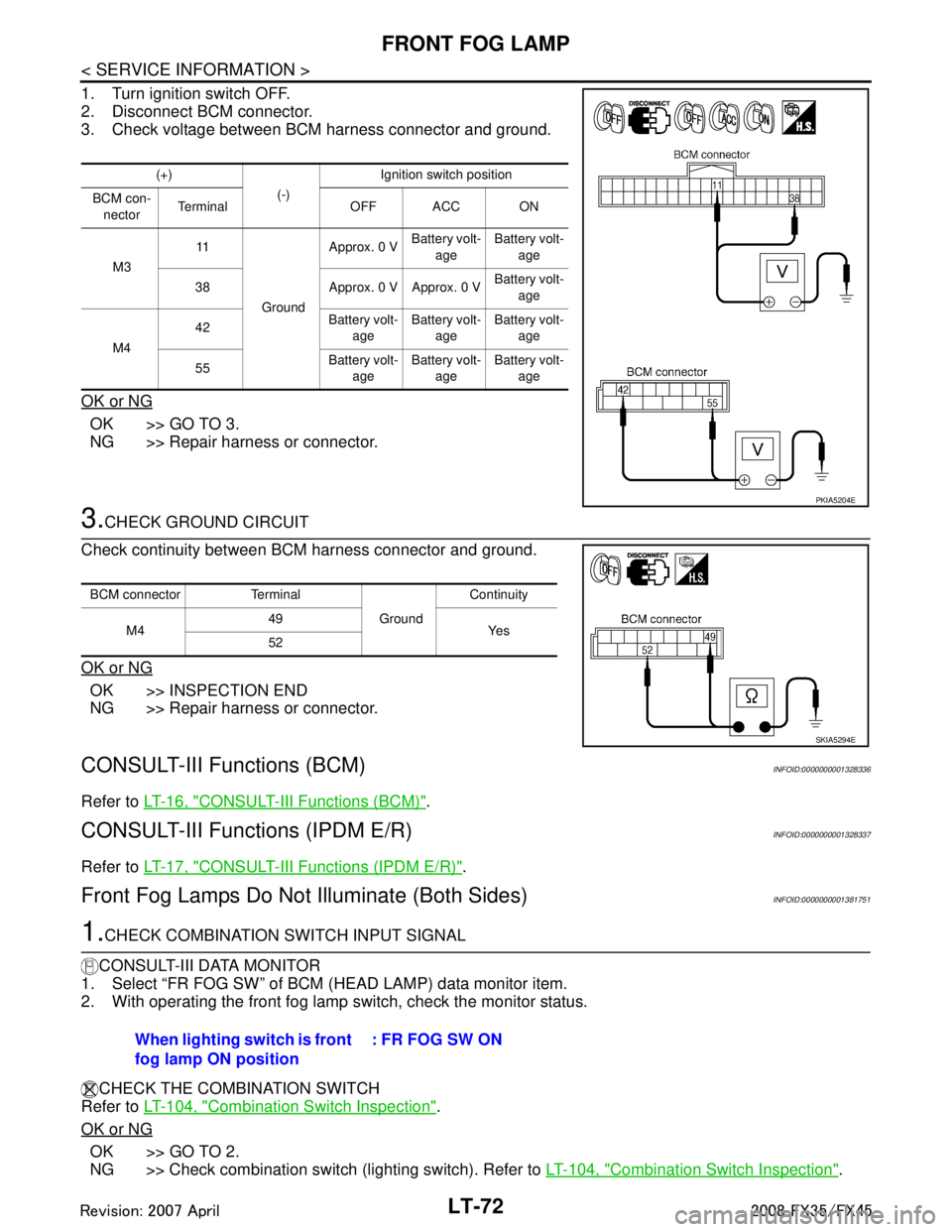
1. Turn ignition switch OFF.
2. Disconnect BCM connector.
3. Check voltage between BCM harness connector and ground.
OK or NG
OK >> GO TO 3.
NG >> Repair harness or connector.
3.CHECK GROUND CIRCUIT
Check continuity between BCM harness connector and ground.
OK or NG
OK >> INSPECTION END
NG >> Repair harness or connector.
CONSULT-III Functions (BCM)INFOID:0000000001328336
Refer to LT-16, "CONSULT-III Functions (BCM)".
CONSULT-III Functions (IPDM E/R)INFOID:0000000001328337
Refer to LT-17, "CONSULT-III Functions (IPDM E/R)".
Front Fog Lamps Do Not Illuminate (Both Sides)INFOID:0000000001381751
1.CHECK COMBINATION SWITCH INPUT SIGNAL
CONSULT-III DATA MONITOR
1. Select “FR FOG SW” of BCM (HEAD LAMP) data monitor item.
2. With operating the front fog lamp switch, check the monitor status.
CHECK THE COMBINATION SWITCH
Refer to LT-104, "
Combination Switch Inspection".
OK or NG
OK >> GO TO 2.
NG >> Check combination switch (lighting switch). Refer to LT-104, "
Combination Switch Inspection".
(+)
(-)Ignition switch position
BCM con- nector Terminal OFF ACC ON
M3 11
Ground Approx. 0 V
Battery volt-
age Battery volt-
age
38 Approx. 0 V Approx. 0 V Battery volt-
age
M4 42
Battery volt-
age Battery volt-
age Battery volt-
age
55 Battery volt-
age Battery volt-
age Battery volt-
age
PKIA5204E
BCM connector Terminal
GroundContinuity
M4 49
Ye s
52
SKIA5294E
When lighting switch is front
fog lamp ON position : FR FOG SW ON
3AA93ABC3ACD3AC03ACA3AC03AC63AC53A913A773A893A873A873A8E3A773A983AC73AC93AC03AC3
3A893A873A873A8F3A773A9D3AAF3A8A3A8C3A863A9D3AAF3A8B3A8C
Page 3175 of 3924
FRONT FOG LAMPLT-73
< SERVICE INFORMATION >
C
DE
F
G H
I
J
L
M A
B
LT
N
O P
2.FRONT FOG LAMP ACTIVE TEST
CONSULT-III ACTIVE TEST
1. Select “LAMPS” of IPDM E/R active test item.
2. With operating the test item, check th at the front fog lamp is turned ON.
IPDM E/R AUTO ACTIVE TEST
1. Start auto active test. Refer to PG-20, "
Auto Active Test".
2. Make sure front fog lamp operation.
OK or NG
OK >> GO TO 3.
NG >> GO TO 4.
3.CHECK IPDM E/R
CONSULT-III DATA MONITOR
1. Select “FR FOG REQ” of IPDM E/R data monitor item.
2. Turn lighting switch 1ST.
3. With operating the front fog lamp switch, check the monitor status.
OK or NG
OK >> Replace IPDM E/R. Refer to PG-24, "Removal and Installation of IPDM E/R".
NG >> Replace BCM. Refer to BCS-13, "
Removal and Installation of BCM".
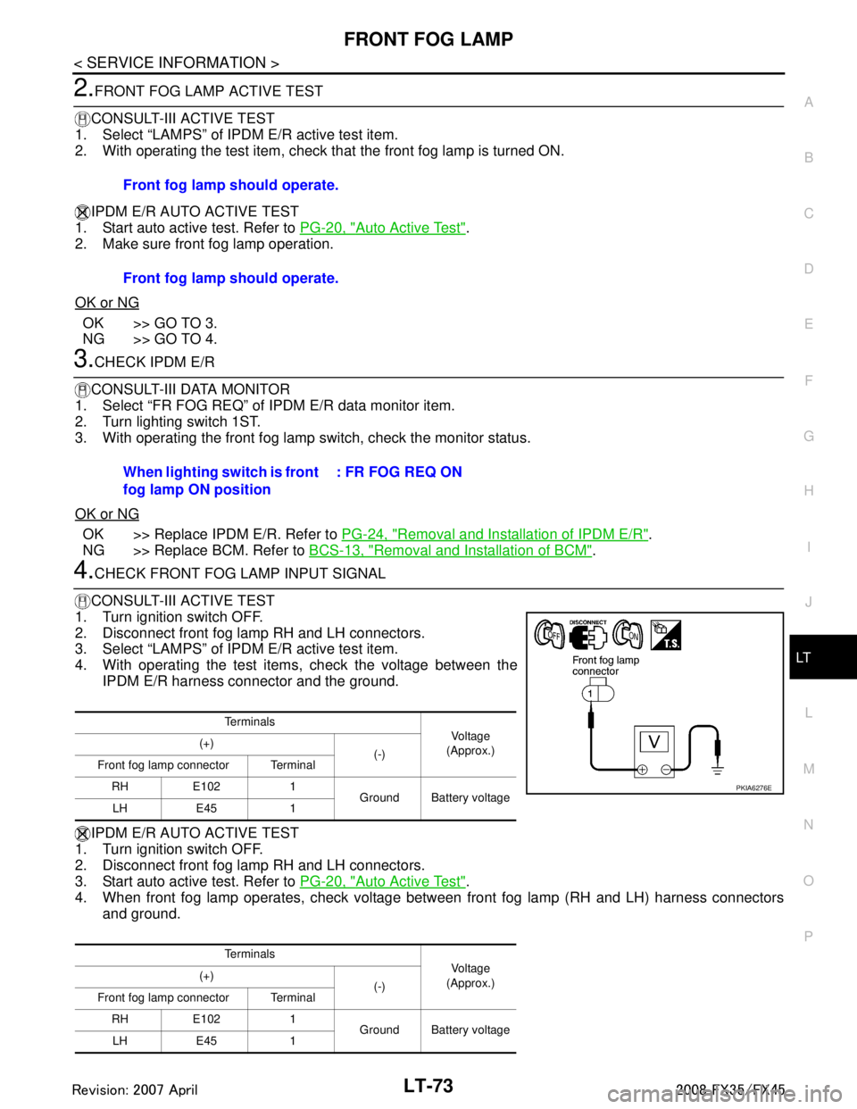
4.CHECK FRONT FOG LAMP INPUT SIGNAL
CONSULT-III ACTIVE TEST
1. Turn ignition switch OFF.
2. Disconnect front fog lamp RH and LH connectors.
3. Select “LAMPS” of IPDM E/R active test item.
4. With operating the test items, check the voltage between the IPDM E/R harness connector and the ground.
IPDM E/R AUTO ACTIVE TEST
1. Turn ignition switch OFF.
2. Disconnect front fog lamp RH and LH connectors.
3. Start auto active test. Refer to PG-20, "
Auto Active Test".
4. When front fog lamp operates, check voltage bet ween front fog lamp (RH and LH) harness connectors
and ground. Front fog lamp should operate.
Front fog lamp should operate.
When lighting switch is front
fog lamp ON position
: FR FOG REQ ON
Te r m i n a l s
Vol tag e
(Approx.)
(+)
(-)
Front fog lamp connector Terminal
RH E102 1 Ground Battery voltage
LH E45 1
Te r m i n a l s Vol tag e
(Approx.)
(+)
(-)
Front fog lamp connector Terminal
RH E102 1 Ground Battery voltage
LH E45 1
PKIA6276E
3AA93ABC3ACD3AC03ACA3AC03AC63AC53A913A773A893A873A873A8E3A773A983AC73AC93AC03AC3
3A893A873A873A8F3A773A9D3AAF3A8A3A8C3A863A9D3AAF3A8B3A8C