2008 INFINITI FX35 radiator
[x] Cancel search: radiatorPage 3339 of 3924
MA-22
< SERVICE INFORMATION >
ENGINE MAINTENANCE (VK45DE ENGINE)
5. Rev engine two or three times under no-load.
6. Stop engine and wait until it cools down.
7. Drain water from the system. Refer to "DRAINING ENGINE COOLANT".
8. Repeat steps 1 through 7 until clear water begins to drain from radiator.
Checking Fuel LineINFOID:0000000001328912
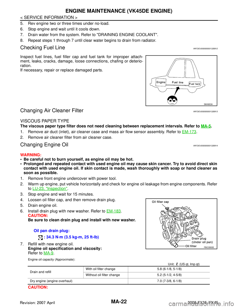
Inspect fuel lines, fuel filler cap and fuel tank for improper attach-
ment, leaks, cracks, damage, loose connections, chafing or deterio-
ration.
If necessary, repair or replace damaged parts.
Changing Air Cleaner FilterINFOID:0000000001328913
VISCOUS PAPER TYPE
The viscous paper type filter does not need cleaning between replacement intervals. Refer to MA-5.
1. Remove air duct (inlet), air cleaner case and mass air flow sensor assembly. Refer to EM-173
.
2. Remove air cleaner filter from air cleaner case.
Changing Engine OilINFOID:0000000001328914
WARNING:
Be careful not to burn yoursel f, as engine oil may be hot.
Prolonged and repeated contact with used engine oil may cause ski n cancer. Try to avoid direct skin
contact with used engine oil. If skin contact is made, wash thoroughly with soap or hand cleaner as
soon as possible.
1. Remove front engine undercover with power tool.
2. Warm up engine, put vehicle horizontally and check for engine oil leakage from engine components. Refer
to LU-23, "
Inspection".
3. Stop engine and wait for 15 minutes.
4. Loosen oil filler cap, and then remove drain plug.
5. Drain engine oil.
6. Install drain plug with new washer. Refer to EM-183
.
CAUTION:
Be sure to clean drain plug and install with new washer.
7. Refill with new engine oil. Engine oil specification and viscosity:
Refer to MA-9
.
Engine oil capacity (Approximate):
Unit: (US qt, Imp qt)
CAUTION:
SMA803A
Oil pan drain plug:
: 34.3 N·m (3.5 kg-m, 25 ft-lb)
PBIC0993E
Drain and refill With oil filter change 5.8 (6-1/8, 5-1/8)
Without oil filter change 5.2 (5-1/2, 4-5/8)
Dry engine (engine overhaul) 7.0 (7-3/8, 6-1/8)
3AA93ABC3ACD3AC03ACA3AC03AC63AC53A913A773A893A873A873A8E3A773A983AC73AC93AC03AC3
3A893A873A873A8F3A773A9D3AAF3A8A3A8C3A863A9D3AAF3A8B3A8C
Page 3344 of 3924
CHASSIS AND BODY MAINTENANCEMA-27
< SERVICE INFORMATION >
C
DE
F
G H
I
J
K
M A
B
MA
N
O P
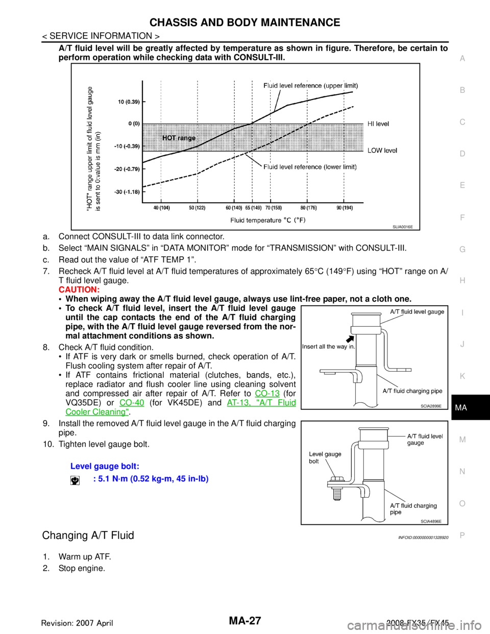
A/T fluid level will be greatly affected by temper ature as shown in figure. Therefore, be certain to
perform operation while checki ng data with CONSULT-III.
a. Connect CONSULT-III to data link connector.
b. Select “MAIN SIGNALS” in “DATA MONITOR” mode for “TRANSMISSION” with CONSULT-III.
c. Read out the value of “ATF TEMP 1”.
7. Recheck A/T fluid level at A/T fluid temperatures of approximately 65 °C (149 °F) using “HOT” range on A/
T fluid level gauge.
CAUTION:
When wiping away the A/T fluid level gauge, always use lint-free paper, not a cloth one.
To check A/T fluid level, inser t the A/T fluid level gauge
until the cap contacts the en d of the A/T fluid charging
pipe, with the A/T fluid level gauge reversed from the nor-
mal attachment conditions as shown.
8. Check A/T fluid condition. If ATF is very dark or smells burned, check operation of A/T.
Flush cooling system after repair of A/T.
If ATF contains frictional material (clutches, bands, etc.), replace radiator and flush cooler line using cleaning solvent
and compressed air after repair of A/T. Refer to CO-13
(for
VQ35DE) or CO-40
(for VK45DE) and AT-13, "A/T Fluid
Cooler Cleaning".
9. Install the removed A/T fluid level gauge in the A/T fluid charging pipe.
10. Tighten level gauge bolt.
Changing A/T FluidINFOID:0000000001328920
1. Warm up ATF.
2. Stop engine. Level gauge bolt:
: 5.1 N·m (0.52 kg-m, 45 in-lb)
SLIA0016E
SCIA2899E
SCIA4896E
3AA93ABC3ACD3AC03ACA3AC03AC63AC53A913A773A893A873A873A8E3A773A983AC73AC93AC03AC3
3A893A873A873A8F3A773A9D3AAF3A8A3A8C3A863A9D3AAF3A8B3A8C
Page 3345 of 3924
MA-28
< SERVICE INFORMATION >
CHASSIS AND BODY MAINTENANCE
3. Loosen the level gauge bolt.
4. Drain ATF from drain plug and refill with new ATF. Always refillsame volume with drained ATF.
To replace the ATF, pour in new ATF at the A/T fluid charging
pipe with the engine idling, at the same time drain the old ATF
from the radiator cooler hose return side.
When the color of the ATF coming out is almost same as the color of the new ATF, the replacement is complete. The
amount of new ATF to use should be 30 to 50% increase of
the stipulated amount.
CAUTION:
Use only Genuine NISSAN Matic J ATF. Do not mix with other ATF.
Using ATF other than Genuine NISSAN Matic J AT F will cause deterioration in driveability and A/
T durability, and may damage the A/T, which is not covered by the warranty.
When filling ATF, take care not to scatter heat generating parts such as exhaust.
Do not reuse drain plug gasket.
5. Run engine at idle speed for 5 minutes.
6. Check A/T fluid level and condition. Refer to MA-26, "
Checking A/T Fluid". If ATF is still dirty, repeat step
2. through 5.
7. Install the removed A/T fluid level gauge into A/T fluid charging pipe.
8. Tighten the level gauge bolt.
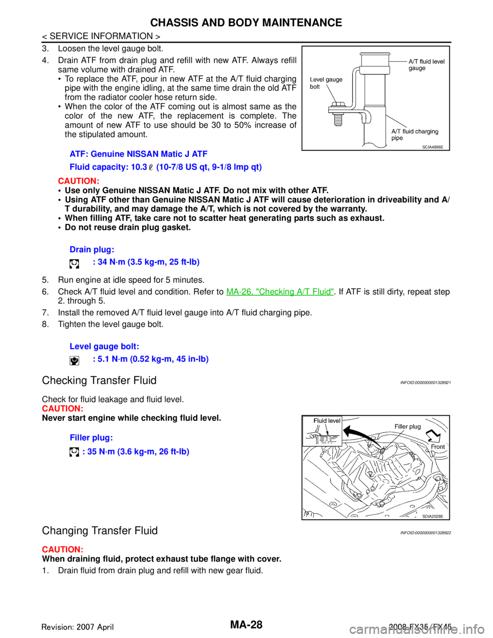
Checking Transfer FluidINFOID:0000000001328921
Check for fluid leakage and fluid level.
CAUTION:
Never start engine while checking fluid level.
Changing Transfer FluidINFOID:0000000001328922
CAUTION:
When draining fluid, protect exh aust tube flange with cover.
1. Drain fluid from drain plug and refill with new gear fluid. ATF: Genuine NISSAN Matic J ATF
Fluid capacity: 10.3 (10-7/8 US qt, 9-1/8 lmp qt)
Drain plug:
: 34 N·m (3.5 kg-m, 25 ft-lb)
Level gauge bolt: : 5.1 N·m (0.52 kg-m, 45 in-lb)
SCIA4896E
Filler plug:
: 35 N·m (3.6 kg-m, 26 ft-lb)
SDIA2028E
3AA93ABC3ACD3AC03ACA3AC03AC63AC53A913A773A893A873A873A8E3A773A983AC73AC93AC03AC3
3A893A873A873A8F3A773A9D3AAF3A8A3A8C3A863A9D3AAF3A8B3A8C
Page 3354 of 3924
SERVICE DATA AND SPECIFICATIONS (SDS)
MA-37
< SERVICE INFORMATION >
C
D E
F
G H
I
J
K
M A
B
MA
N
O P
SERVICE DATA AND SPECIFICATIONS (SDS)
Standard and LimitINFOID:0000000001328938
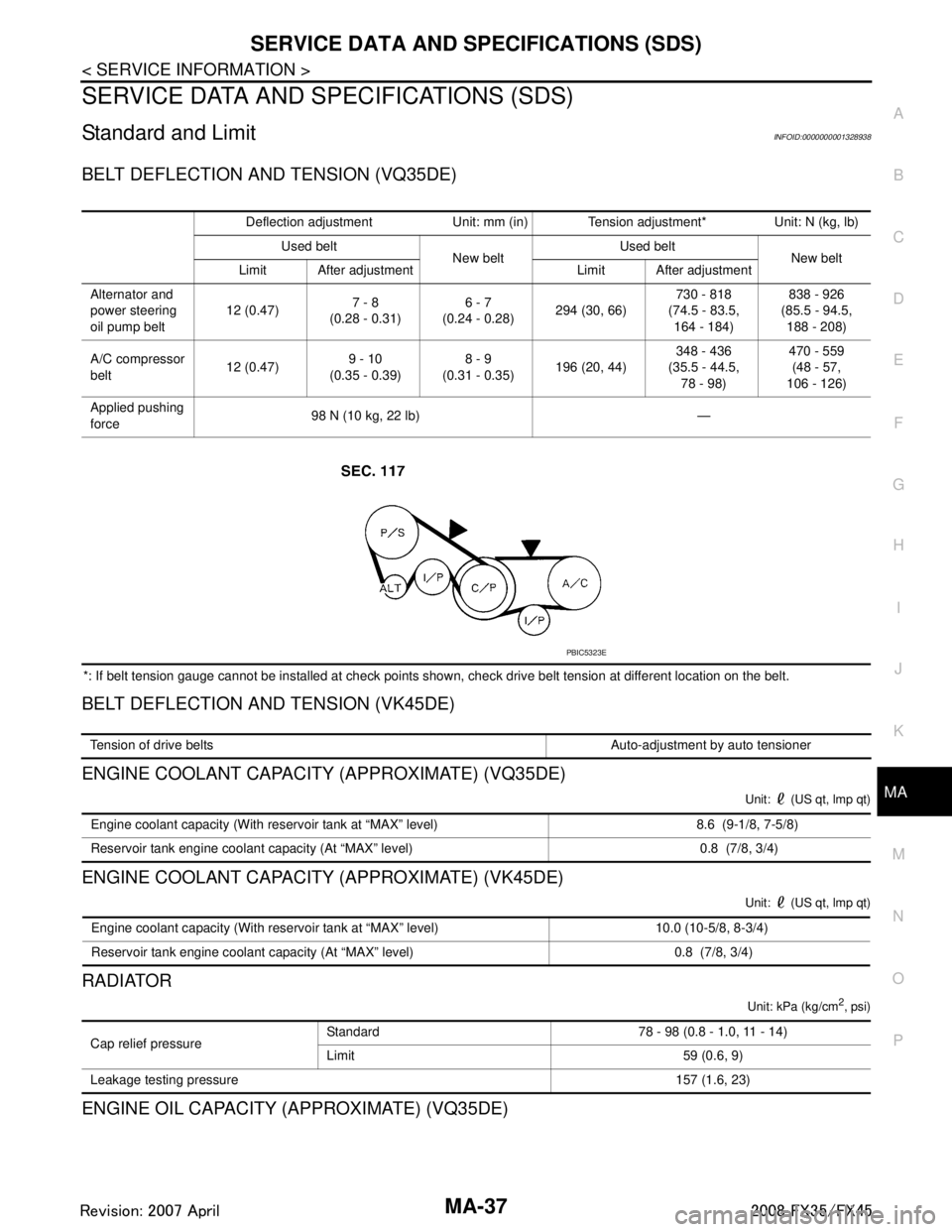
BELT DEFLECTION AND TENSION (VQ35DE)
*: If belt tension gauge cannot be installed at check points shown, check drive belt tension at different location on the belt.
BELT DEFLECTION AND TENSION (VK45DE)
ENGINE COOLANT CAPACITY (APPROXIMATE) (VQ35DE)
Unit: (US qt, lmp qt)
ENGINE COOLANT CAPACITY (APPROXIMATE) (VK45DE)
Unit: (US qt, lmp qt)
RADIATOR
Unit: kPa (kg/cm2, psi)
ENGINE OIL CAPACITY (APPROXIMATE) (VQ35DE)
Deflection adjustment Unit: mm (in) Tension adjustment* Unit: N (kg, lb) Used belt New beltUsed belt
New belt
Limit After adjustment Limit After adjustment
Alternator and
power steering
oil pump belt 12 (0.47)
7 - 8
(0.28 - 0.31) 6 - 7
(0.24 - 0.28) 294 (30, 66) 730 - 818
(74.5 - 83.5, 164 - 184) 838 - 926
(85.5 - 94.5, 188 - 208)
A/C compressor
belt 12 (0.47)
9 - 10
(0.35 - 0.39) 8 - 9
(0.31 - 0.35) 196 (20, 44) 348 - 436
(35.5 - 44.5,
78 - 98) 470 - 559
(48 - 57,
106 - 126)
Applied pushing
force 98 N (10 kg, 22 lb) —
PBIC5323E
Tension of drive belts Auto-adjustment by auto tensioner
Engine coolant capacity (With reservoir tank at “MAX” level) 8.6 (9-1/8, 7-5/8)
Reservoir tank engine coolant capacity (At “MAX” level) 0.8 (7/8, 3/4)
Engine coolant capacity (With reservoir tank at “MAX” level) 10.0 (10-5/8, 8-3/4)
Reservoir tank engine coolant capacity (At “MAX” level) 0.8 (7/8, 3/4)
Cap relief pressure Standard 78 - 98 (0.8 - 1.0, 11 - 14)
Limit 59 (0.6, 9)
Leakage testing pressure 157 (1.6, 23)
3AA93ABC3ACD3AC03ACA3AC03AC63AC53A913A773A893A873A873A8E3A773A983AC73AC93AC03AC3
3A893A873A873A8F3A773A9D3AAF3A8A3A8C3A863A9D3AAF3A8B3A8C
Page 3522 of 3924

SQUEAK AND RATTLE TROUBLE DIAGNOSESRF-7
< SERVICE INFORMATION >
C
DE
F
G H
J
K L
M A
B
RF
N
O P
Most of these incidents can be repaired by adjusting, se curing or insulating the item(s) or component(s) caus-
ing the noise.
SUNROOF/HEADLINING
Noises in the sunroof/headlining area can often be traced to one of the following:
1. Sunroof lid, rail, linkage or seals making a rattle or light knocking noise
2. Sunvisor shaft shaking in the holder
3. Front or rear windshield touching headlining and squeaking
Again, pressing on the components to stop the noise while duplicating the conditions can isolate most of these
incidents. Repairs usually consist of insulating with felt cloth tape.
SEATS
When isolating seat noise it's important to note the pos ition the seat is in and the load placed on the seat when
the noise is present. These conditions should be duplic ated when verifying and isolating the cause of the
noise.
Cause of seat noise include:
1. Headrest rods and holder
2. A squeak between the seat pad cushion and frame
3. Rear seatback lock and bracket
These noises can be isolated by moving or pressing on the suspected components while duplicating the con-
ditions under which the noise occurs. Most of thes e incidents can be repaired by repositioning the component
or applying urethane tape to the contact area.
UNDERHOOD
Some interior noise may be caused by components under the hood or on the engine wall. The noise is then
transmitted into the passenger compartment.
Causes of transmitted underhood noise include:
1. Any component mounted to the engine wall
2. Components that pass through the engine wall
3. Engine wall mounts and connectors
4. Loose radiator mounting pins
5. Hood bumpers out of adjustment
6. Hood striker out of adjustment
These noises can be difficult to isolate since they cannot be reached from the interior of the vehicle. The best
method is to secure, move or insulate one component at a time and test drive the vehicle. Also, engine RPM
or load can be changed to isolate the noise. Repairs c an usually be made by moving, adjusting, securing, or
insulating the component causing the noise.
3AA93ABC3ACD3AC03ACA3AC03AC63AC53A913A773A893A873A873A8E3A773A983AC73AC93AC03AC3
3A893A873A873A8F3A773A9D3AAF3A8A3A8C3A863A9D3AAF3A8B3A8C
Page 3634 of 3924
CHARGING SYSTEMSC-25
< SERVICE INFORMATION >
C
DE
F
G H
I
J
L
M A
B
SC
N
O P
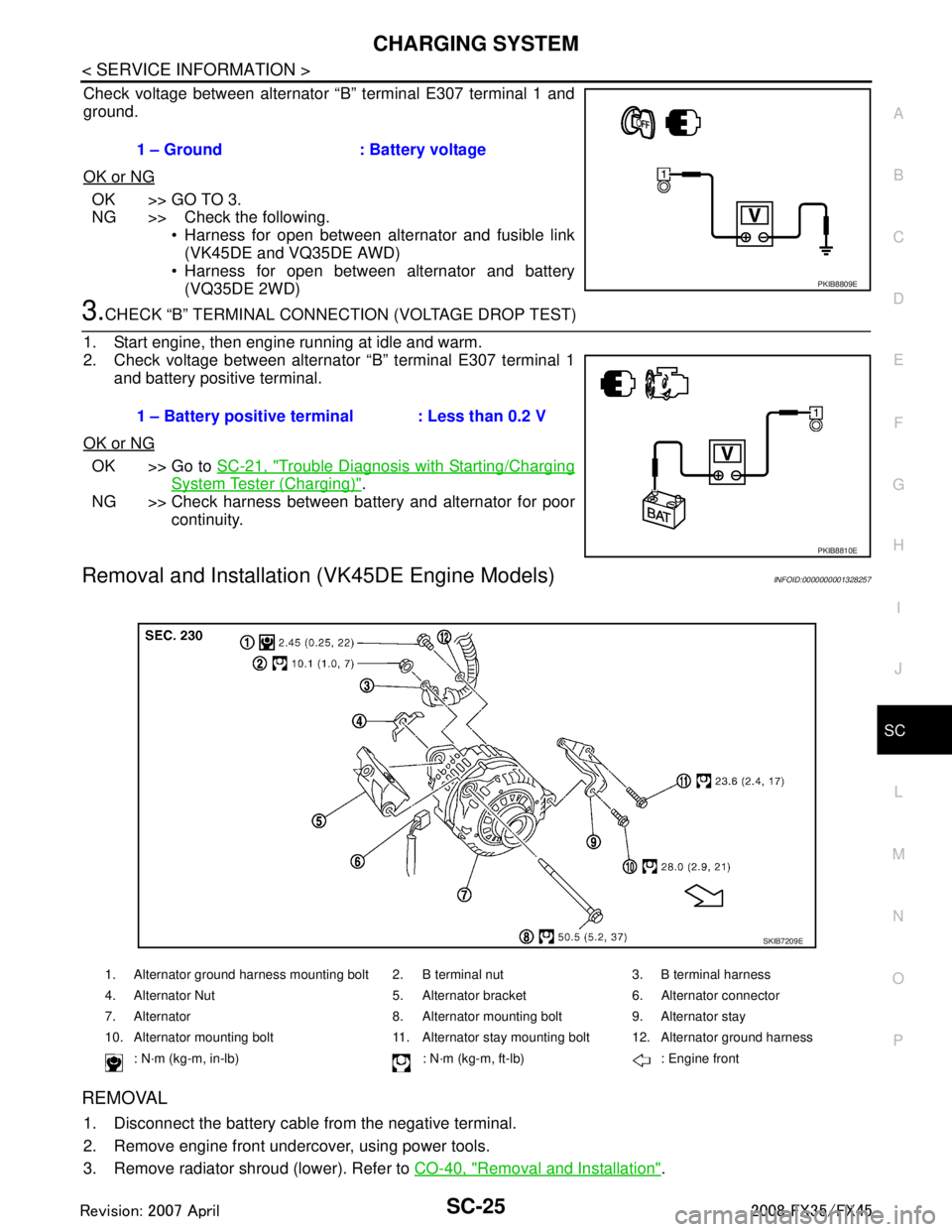
Check voltage between alternator “B” terminal E307 terminal 1 and
ground.
OK or NG
OK >> GO TO 3.
NG >> Check the following. Harness for open between alternator and fusible link
(VK45DE and VQ35DE AWD)
Harness for open between alternator and battery
(VQ35DE 2WD)
3.CHECK “B” TERMINAL CONNECT ION (VOLTAGE DROP TEST)
1. Start engine, then engine running at idle and warm.
2. Check voltage between alternator “B” terminal E307 terminal 1 and battery positive terminal.
OK or NG
OK >> Go to SC-21, "Trouble Diagnosis with Starting/Charging
System Tester (Charging)".
NG >> Check harness between battery and alternator for poor continuity.
Removal and Installation (VK45DE Engine Models)INFOID:0000000001328257
REMOVAL
1. Disconnect the battery cabl e from the negative terminal.
2. Remove engine front undercover, using power tools.
3. Remove radiator shroud (lower). Refer to CO-40, "
Removal and Installation".
1 – Ground : Battery voltage
PKIB8809E
1 – Battery positive terminal : Less than 0.2 V
PKIB8810E
1. Alternator ground harness mounting bolt 2. B terminal nut 3. B terminal harness
4. Alternator Nut 5. Alternator bracket 6. Alternator connector
7. Alternator 8. Alternator mounting bolt 9. Alternator stay
10. Alternator mounting bolt 11. Alternator stay mounting bolt 12. Alternator ground harness
: N·m (kg-m, in-lb) : N·m (kg-m, ft-lb) : Engine front
SKIB7209E
3AA93ABC3ACD3AC03ACA3AC03AC63AC53A913A773A893A873A873A8E3A773A983AC73AC93AC03AC3
3A893A873A873A8F3A773A9D3AAF3A8A3A8C3A863A9D3AAF3A8B3A8C
Page 3648 of 3924

SQUEAK AND RATTLE TROUBLE DIAGNOSESSE-9
< SERVICE INFORMATION >
C
DE
F
G H
J
K L
M A
B
SE
N
O P
Most of these incidents can be repaired by adjusting, se curing or insulating the item(s) or component(s) caus-
ing the noise.
SUNROOF/HEADLINING
Noises in the sunroof/headlining area can often be traced to one of the following:
1. Sunroof lid, rail, linkage or seals making a rattle or light knocking noise
2. Sun-visor shaft shaking in the holder
3. Front or rear windshield touching headlining and squeaking
Again, pressing on the components to stop the noise while duplicating the conditions can isolate most of these
incidents. Repairs usually consist of insulating with felt cloth tape.
SEATS
When isolating seat noise it's important to note the pos ition the seat is in and the load placed on the seat when
the noise is present. These conditions should be duplic ated when verifying and isolating the cause of the
noise.
Cause of seat noise include:
1. Headrest rods and holder
2. A squeak between the seat pad cushion and frame
3. The rear seatback lock and bracket
These noises can be isolated by moving or pressing on the suspected components while duplicating the con-
ditions under which the noise occurs. Most of thes e incidents can be repaired by repositioning the component
or applying urethane tape to the contact area.
UNDERHOOD
Some interior noise may be caused by components under the hood or on the engine wall. The noise is then
transmitted into the passenger compartment.
Causes of transmitted under-hood noise include:
1. Any component mounted to the engine wall
2. Components that pass through the engine wall
3. Engine wall mounts and connectors
4. Loose radiator mounting pins
5. Hood bumpers out of adjustment
6. Hood striker out of adjustment
These noises can be difficult to isolate since they cannot be reached from the interior of the vehicle. The best
method is to secure, move or insulate one component at a time and test drive the vehicle. Also, engine RPM
or load can be changed to isolate the noise. Repairs c an usually be made by moving, adjusting, securing, or
insulating the component causing the noise.
3AA93ABC3ACD3AC03ACA3AC03AC63AC53A913A773A893A873A873A8E3A773A983AC73AC93AC03AC3
3A893A873A873A8F3A773A9D3AAF3A8A3A8C3A863A9D3AAF3A8B3A8C