2008 INFINITI FX35 door lock
[x] Cancel search: door lockPage 917 of 3924

VEHICLE SECURITY (THEFT WARNING) SYSTEMBL-183
< SERVICE INFORMATION >
C
DE
F
G H
J
K L
M A
B
BL
N
O P
With CONSULT-III
Check (“THEFT IND”) in “ACTIV E TEST” mode with CONSULT-III.
Without CONSULT-III
Check voltage between BCM connector and ground.
OK or NG
OK >> Security indicator lamp is OK.
NG >> GO TO 2.
2.CHECK HARNESS CONTINUITY
1. Turn ignition switch OFF.
2. Disconnect BCM and security indicator lamp connector.
3. Check continuity between BCM connector M3 terminal 23 and security indicator lamp connector M38 terminal 2.
OK or NG
OK >> Check the following. Harness for open or short between BCM and securityindicator lamp.
10A fuse [No.19, located in fuse block (J/B)]
NG >> Repair or replace harness between BCM and security indicator lamp.
Diagnosis Procedure 3INFOID:0000000001327918
FRONT DOOR KEY CYLINDER SWITCH CHECK
1.CHECK KEY CYLINDER SWITCH OPERATION
Check door key cylinder switch using key.
Do doors lock / unlock when using the key?
YES >> Front door key cylinder switch operation is OK.
NO >> Check door key cylinder switch circuit. Refer to GW-43, "
Check Front Door Key Cylinder Switch".
Diagnosis Procedure 4INFOID:0000000001327919
VEHICLE SECURITY HORN ALARM CHECK
1.CHECK HORN OPERATION
Check if horn sounds with horn switch.
Does horn operate?
YES >> Check harness for open or shor t between IPDM E/R and horn relay.
NO >> Check horn circuit. Refer to WW-48
.
Diagnosis Procedure 5INFOID:0000000001327920
VEHICLE SECURITY HEADLAMP ALARM CHECK
Perform operation shown on display indicator lamp
should illuminate.
Connector Terminals (Wire color)
ConditionVoltage (V)
(Approx.)
(+) (-)
M3 23 (G/OR) Ground Illuminates 0
Goes off Battery voltage
PIIA6230E
23 (G/OR) – 2 (G/OR) : Co
ntinuity should exist.
PIIA6231E
3AA93ABC3ACD3AC03ACA3AC03AC63AC53A913A773A893A873A873A8E3A773A983AC73AC93AC03AC3
3A893A873A873A8F3A773A9D3AAF3A8A3A8C3A863A9D3AAF3A8B3A8C
Page 918 of 3924

BL-184
< SERVICE INFORMATION >
VEHICLE SECURITY (THEFT WARNING) SYSTEM
1.CHECK HEADLAMP OPERATION
Check if headlamp operates by lighting switch.
Does headlamp come on when turning switch
“ON”?
YES >> Headlamp alarm circuit is OK.
NO >> Check headlamp system. Refer to LT- 5
or LT- 3 2.
Diagnosis Procedure 6INFOID:0000000001327921
DOOR LOCK AND UNLOCK SWITCH CHECK
1.CHECK DOOR LOCK AND UNLOCK SWITCH INPUT SIGNAL
Check if power door lock operated by door lock and unlock switch.
Do doors lock / unlock when using each door lock and unlock switches?
YES >> Door lock and unlock switch is OK.
NO >> Check door lock and unlock switch. Refer to BL-43, "
Check Door Lock and Unlock Switch".
3AA93ABC3ACD3AC03ACA3AC03AC63AC53A913A773A893A873A873A8E3A773A983AC73AC93AC03AC3
3A893A873A873A8F3A773A9D3AAF3A8A3A8C3A863A9D3AAF3A8B3A8C
Page 1128 of 3924

DI-2
CONSULT-III Function (BCM) ................................60
Trouble Diagnosis ...................................................61
Symptom Chart .......................................................61
Power Supply and Ground Circuit Inspection .........61
Combination Meter Buzzer Circuit Inspection .........62
Front Door Switch (Driver Side) Signal Inspection ...63
Key Switch Signal Inspection (Without Intelligent
Key) ..................................................................... ...
64
Key Switch and Ignition Knob Switch Signal In-
spection (With Intelligent Key, When Mechanical
Key Is Used) ........................................................ ...
65
Lighting Switch Signal Inspection ...........................66
Seat Belt Buckle Switch (Driver Side) Signal In-
spection ............................................................... ...
66
Component Inspection ............................................67
LANE DEPARTURE WARNING SYSTEM ........69
Precaution for Lane Departure Warning (LDW)
system ................................................................. ...
69
System Description .................................................69
Action Test ..............................................................71
Camera Aiming Adjustment ....................................71
Component Parts and Harness Connector Loca-
tion ..........................................................................
76
Schematic ...............................................................77
Wiring Diagram - LDW - .........................................78
Terminal and Reference Value for LDW Camera
Unit .........................................................................
81
CONSULT-III Function (LDW) ................................81
Trouble Diagnosis ...................................................83
Preliminary Check ..................................................84
Power Supply and Ground Circuit Inspection .........84
DTC [C1B00] CAMERA UNIT MALF ......................85
DTC [C1B01] CAM AIMING INCMP .......................85
DTC [C1B02] VHCL SPD DATA MALF ..................85
DTC [C1B03] ABNRML TEMP DETECT ................86
DTC [U1000] CAN COMM CIRCUIT ......................86
DTC [U1010] CONTROL UNIT (CAN) ....................86
LDW Chime Circuit Inspection ................................86
LDW Switch Circuit Inspection ...............................88
LDW Indicator Lamp Circuit Inspection ..................90
Turn Signal Input Inspection ................................ ...91
Electrical Component Inspection ............................91
Removal and Installation for LDW Camera Unit .....91
Removal and Installation for LDW Chime ............ ...91
Removal and Installation for LDW Switch ...............92
CAN COMMUNICATION ...................................93
System Description .............................................. ...93
CAN Communication Unit .......................................93
COMPASS .........................................................94
Precaution for Compass ...................................... ...94
System Description .................................................94
Troubleshooting ......................................................94
Zone Variation Setting Procedure ...........................95
Calibration Procedure .............................................95
Wiring Diagram - COMPAS - ..................................97
Removal and Installation of Compass ....................97
CLOCK ..............................................................98
Wiring Diagram - CLOCK - .................................. ...98
Removal and Installation of Clock ...........................98
REAR VIEW MONITOR ....................................100
System Description .............................................. .100
Component Parts and Harness Connector Loca-
tion ........................................................................
101
Schematic .............................................................102
Wiring Diagram - R/VIEW - ...................................103
Terminal and Reference Value for Rear View
Camera Control Unit .............................................
106
CONSULT-III Function (REARVIEW CAMERA) ...106
Side Distance Guideline Correction ......................107
Power Supply and Ground Circuit Inspection .......108
Rear View Is Not Displayed with the A/T Selector
Lever in R-Position ................................................
108
The Rear View Image Is Distorted ........................112
Removal and Installation of Rear View Camera
Control Unit .......................................................... .
113
Removal and Installation of Rear View Camera ...113
3AA93ABC3ACD3AC03ACA3AC03AC63AC53A913A773A893A873A873A8E3A773A983AC73AC93AC03AC3
3A893A873A873A8F3A773A9D3AAF3A8A3A8C3A863A9D3AAF3A8B3A8C
Page 1177 of 3924
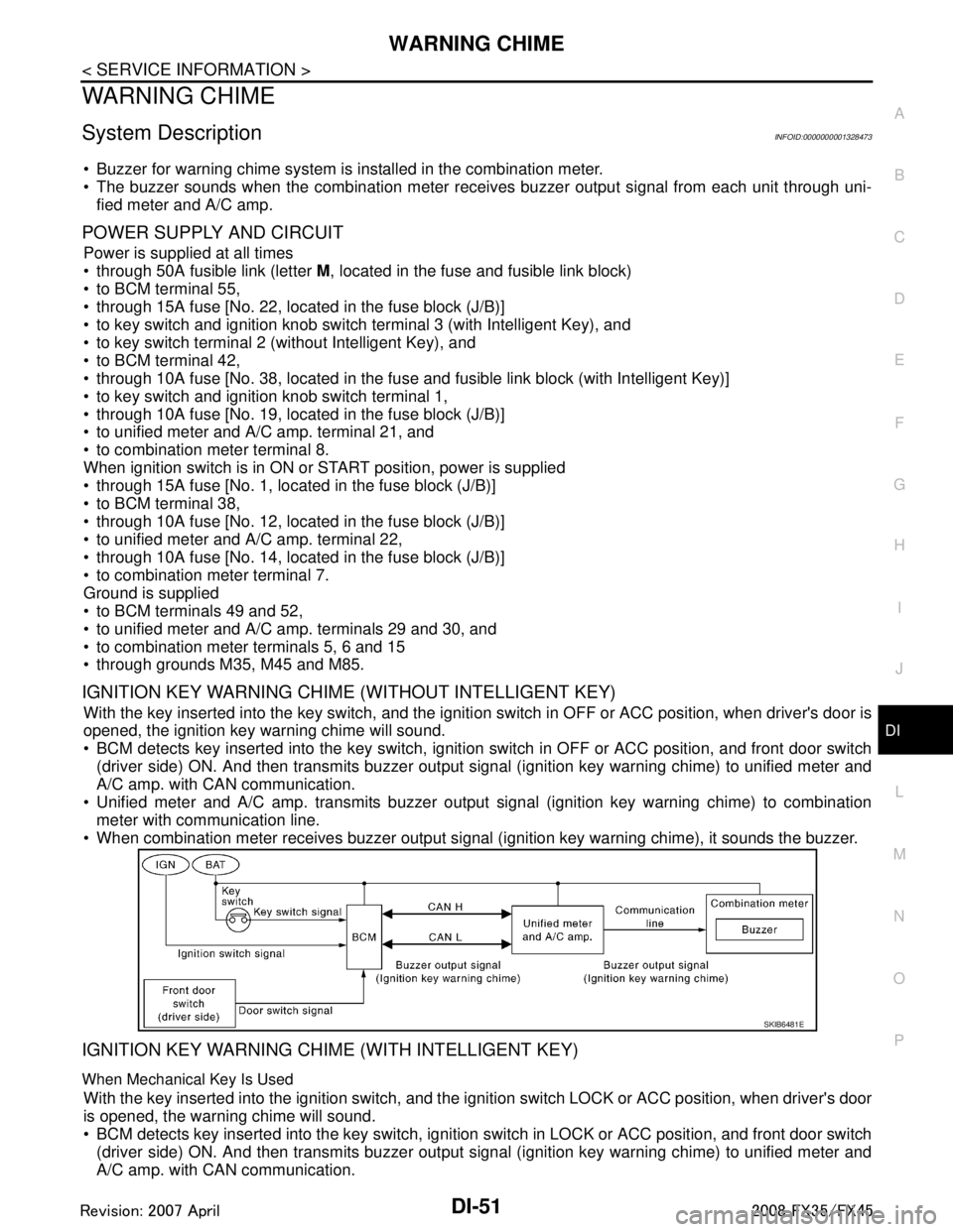
WARNING CHIMEDI-51
< SERVICE INFORMATION >
C
DE
F
G H
I
J
L
M A
B
DI
N
O P
WARNING CHIME
System DescriptionINFOID:0000000001328473
Buzzer for warning chime system is installed in the combination meter.
The buzzer sounds when the combination meter receives buzzer output signal from each unit through uni- fied meter and A/C amp.
POWER SUPPLY AND CIRCUIT
Power is supplied at all times
through 50A fusible link (letter M, located in the fuse and fusible link block)
to BCM terminal 55,
through 15A fuse [No. 22, located in the fuse block (J/B)]
to key switch and ignition knob switch terminal 3 (with Intelligent Key), and
to key switch terminal 2 (without Intelligent Key), and
to BCM terminal 42,
through 10A fuse [No. 38, located in the fuse and fusible link block (with Intelligent Key)]
to key switch and ignition knob switch terminal 1,
through 10A fuse [No. 19, located in the fuse block (J/B)]
to unified meter and A/C amp. terminal 21, and
to combination meter terminal 8.
When ignition switch is in ON or START position, power is supplied
through 15A fuse [No. 1, located in the fuse block (J/B)]
to BCM terminal 38,
through 10A fuse [No. 12, located in the fuse block (J/B)]
to unified meter and A/C amp. terminal 22,
through 10A fuse [No. 14, located in the fuse block (J/B)]
to combination meter terminal 7.
Ground is supplied
to BCM terminals 49 and 52,
to unified meter and A/C amp. terminals 29 and 30, and
to combination meter terminals 5, 6 and 15
through grounds M35, M45 and M85.
IGNITION KEY WARNING CHIME (WITHOUT INTELLIGENT KEY)
With the key inserted into the key switch, and the igniti on switch in OFF or ACC position, when driver's door is
opened, the ignition key warning chime will sound.
BCM detects key inserted into the key switch, igniti on switch in OFF or ACC position, and front door switch
(driver side) ON. And then transmits buzzer output signal (ignition key warning chime) to unified meter and
A/C amp. with CAN communication.
Unified meter and A/C amp. transmits buzzer output signal (ignition key warning chime) to combination
meter with communication line.
When combination meter receives buzzer output signal (ignition key warning chime), it sounds the buzzer.
IGNITION KEY WARNING CHIME (WITH INTELLIGENT KEY)
When Mechanical Key Is Used
With the key inserted into the ignition switch, and the i gnition switch LOCK or ACC position, when driver's door
is opened, the warning chime will sound.
BCM detects key inserted into the key switch, ignition switch in LOCK or ACC position, and front door switch
(driver side) ON. And then transmits buzzer output signal (ignition key warning chime) to unified meter and
A/C amp. with CAN communication.
SKIB6481E
3AA93ABC3ACD3AC03ACA3AC03AC63AC53A913A773A893A873A873A8E3A773A983AC73AC93AC03AC3
3A893A873A873A8F3A773A9D3AAF3A8A3A8C3A863A9D3AAF3A8B3A8C
Page 1178 of 3924
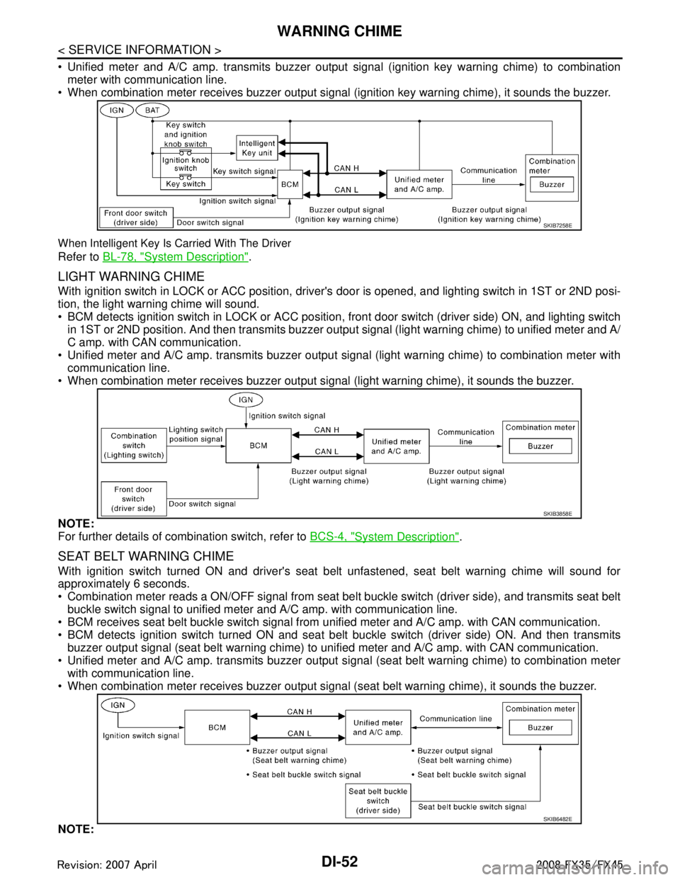
DI-52
< SERVICE INFORMATION >
WARNING CHIME
Unified meter and A/C amp. transmits buzzer output signal (ignition key warning chime) to combinationmeter with communication line.
When combination meter receives buzzer output signal (ignition key warning chime), it sounds the buzzer.
When Intelligent Key Is Carried With The Driver
Refer to BL-78, "System Description".
LIGHT WARNING CHIME
With ignition switch in LOCK or ACC position, driver 's door is opened, and lighting switch in 1ST or 2ND posi-
tion, the light warning chime will sound.
BCM detects ignition switch in LOCK or ACC position, front door switch (driver side) ON, and lighting switch
in 1ST or 2ND position. And then transmits buzzer output signal (light warning chime) to unified meter and A/
C amp. with CAN communication.
Unified meter and A/C amp. transmits buzzer output signal (light warning chime) to combination meter with
communication line.
When combination meter receives buzzer output signal (light warning chime), it sounds the buzzer.
NOTE:
For further details of combination switch, refer to BCS-4, "
System Description".
SEAT BELT WARNING CHIME
With ignition switch turned ON and driver's seat belt unfastened, seat belt warning chime will sound for
approximately 6 seconds.
Combination meter reads a ON/OFF signal from seat bel t buckle switch (driver side), and transmits seat belt
buckle switch signal to unified meter and A/C amp. with communication line.
BCM receives seat belt buckle switch signal from unified meter and A/C amp. with CAN communication.
BCM detects ignition switch turned ON and seat bel t buckle switch (driver side) ON. And then transmits
buzzer output signal (seat belt warning chime) to unified meter and A/C amp. with CAN communication.
Unified meter and A/C amp. transmits buzzer output signal (seat belt warning chime) to combination meter with communication line.
When combination meter receives buzzer output signal (seat belt warning chime), it sounds the buzzer.
NOTE:
SKIB7258E
SKIB3858E
SKIB6482E
3AA93ABC3ACD3AC03ACA3AC03AC63AC53A913A773A893A873A873A8E3A773A983AC73AC93AC03AC3
3A893A873A873A8F3A773A9D3AAF3A8A3A8C3A863A9D3AAF3A8B3A8C
Page 1222 of 3924
DI-96
< SERVICE INFORMATION >
COMPASS
if an aftermarket (i.e., non original equipment) antenna with a magnetic base is attached to the vehicle. Cali-
brate the mirror compass if the display shows onl y one direction or a limited number of directions.
NOTE:
If “magnetic hats” are used in the dealership for vehicle identification, remove the hat from the vehicle before
performing the following steps. Do NOT put the hat back on the vehicle after the procedure is completed.
Drive the vehicle to an open level area; away from large metallic objects, structures, and overhead power
lines.
Turn off “non-essential” electrical accessories (r ear window defrost, heater/air conditioning, wipers) and
close the doors.
1. Verify the correct compass zone setting for the geographical location. Refer to DI-95, "
Zone Variation Set-
ting Procedure".
2. Press and hold the inside mirror switch for more than 9 seconds.
3. “C” is displayed on the compass display, when calibration starts.
4. Drive slowly [less than 8 km/h (5 mph)] in a circle until the “C / CAL” is replaced with primary headings (N,
NE, E, SE, S, SW, W, or NW).
NOTE:
This will require driving at least 2 complete 360 degree circles; 3 complete circles may be required.
5. The compass calibration procedure is now complete. The compass should operate normally. NOTE:
If at any time the compass continually displays the in correct direction or the reading is erratic or locked,
repeat the calibration procedure.
3AA93ABC3ACD3AC03ACA3AC03AC63AC53A913A773A893A873A873A8E3A773A983AC73AC93AC03AC3
3A893A873A873A8F3A773A9D3AAF3A8A3A8C3A863A9D3AAF3A8B3A8C
Page 1239 of 3924
REAR VIEW MONITORDI-113
< SERVICE INFORMATION >
C
DE
F
G H
I
J
L
M A
B
DI
N
O P
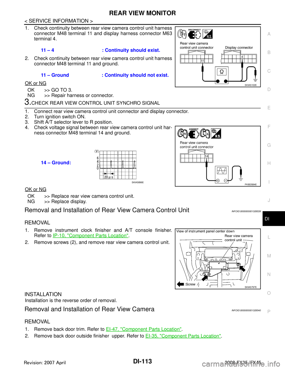
1. Check continuity between rear view camera control unit harness connector M48 terminal 11 and display harness connector M63
terminal 4.
2. Check continuity between rear view camera control unit harness connector M48 terminal 11 and ground.
OK or NG
OK >> GO TO 3.
NG >> Repair harness or connector.
3.CHECK REAR VIEW CONTROL UNIT SYNCHRO SIGNAL
1. Connect rear view camera control unit connector and display connector.
2. Turn ignition switch ON.
3. Shift A/T selector lever to R position.
4. Check voltage signal between rear view camera control unit har- ness connector M48 terminal 14 and ground.
OK or NG
OK >> Replace rear view camera control unit.
NG >> Replace display.
Removal and Installation of R ear View Camera Control UnitINFOID:0000000001328539
REMOVAL
1. Remove instrument clock finisher and A/T console finisher.
Refer to IP-10, "
Component Parts Location".
2. Remove screws (2), and remove rear view camera control unit.
INSTALLATION
Installation is the reverse order of removal.
Removal and Installation of Rear View CameraINFOID:0000000001328540
REMOVAL
1. Remove back door trim. Refer to EI-47, "Component Parts Location".
2. Remove back door outside finisher upper. Refer to EI-35, "
Component Parts Location".
11 – 4 : Continuity should exist.
11 – Ground : Continuity should not exist.
SKIA5102E
14 – Ground:
PKIB3584ESKIA5896E
SKIA5797E
3AA93ABC3ACD3AC03ACA3AC03AC63AC53A913A773A893A873A873A8E3A773A983AC73AC93AC03AC3
3A893A873A873A8F3A773A9D3AAF3A8A3A8C3A863A9D3AAF3A8B3A8C
Page 2442 of 3924
SQUEAK AND RATTLE TROUBLE DIAGNOSESEI-5
< SERVICE INFORMATION >
C
DE
F
G H
J
K L
M A
B
EI
N
O P
SQUEAK AND RATTLE TROUBLE DIAGNOSES
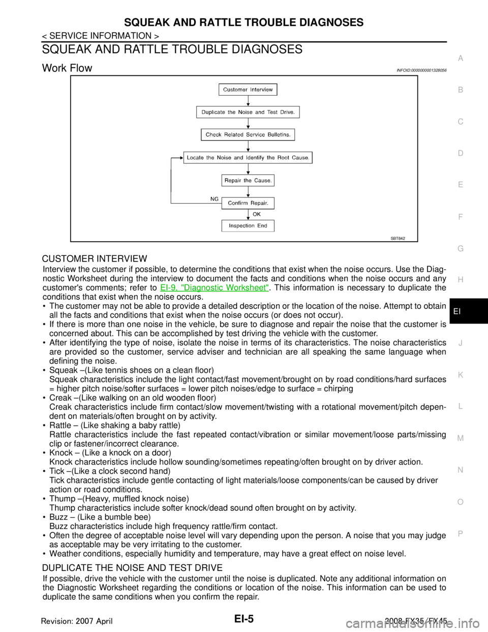
Work FlowINFOID:0000000001328056
CUSTOMER INTERVIEW
Interview the customer if possible, to determine the conditions that exist when the noise occurs. Use the Diag-
nostic Worksheet during the interv iew to document the facts and conditions when the noise occurs and any
customer's comments; refer to EI-9, "
Diagnostic Worksheet". This information is necessary to duplicate the
conditions that exist when the noise occurs.
The customer may not be able to provide a detailed description or the location of the noise. Attempt to obtain all the facts and conditions that exist when the noise occurs (or does not occur).
If there is more than one noise in the vehicle, be sure to diagnose and repair the noise that the customer is
concerned about. This can be accomplished by test driving the vehicle with the customer.
After identifying the type of noise, isolate the noise in terms of its characteristics. The noise characteristics
are provided so the customer, service adviser and technician are all speaking the same language when
defining the noise.
Squeak –(Like tennis shoes on a clean floor)
Squeak characteristics include the light contact/fast movement/brought on by road conditions/hard surfaces
= higher pitch noise/softer surfaces = lower pitch noises/edge to surface = chirping
Creak –(Like walking on an old wooden floor)
Creak characteristics include firm contact/slow mo vement/twisting with a rotational movement/pitch depen-
dent on materials/often brought on by activity.
Rattle – (Like shaking a baby rattle)
Rattle characteristics include the fast repeated contac t/vibration or similar movement/loose parts/missing
clip or fastener/incorrect clearance.
Knock – (Like a knock on a door)
Knock characteristics include hollow sounding/someti mes repeating/often brought on by driver action.
Tick –(Like a clock second hand) Tick characteristics include gentle contacting of li ght materials/loose components/can be caused by driver
action or road conditions.
Thump –(Heavy, muffled knock noise) Thump characteristics include softer k nock/dead sound often brought on by activity.
Buzz – (Like a bumble bee)
Buzz characteristics include high frequency rattle/firm contact.
Often the degree of acceptable noise level will vary depending upon the person. A noise that you may judge as acceptable may be very irritating to the customer.
Weather conditions, especially humidity and temperat ure, may have a great effect on noise level.
DUPLICATE THE NOISE AND TEST DRIVE
If possible, drive the vehicle with the customer until the noise is duplicated. Note any additional information on
the Diagnostic Worksheet regarding the conditions or lo cation of the noise. This information can be used to
duplicate the same conditions when you confirm the repair.
SBT842
3AA93ABC3ACD3AC03ACA3AC03AC63AC53A913A773A893A873A873A8E3A773A983AC73AC93AC03AC3
3A893A873A873A8F3A773A9D3AAF3A8A3A8C3A863A9D3AAF3A8B3A8C