2008 Hyundai Santa Fe lower
[x] Cancel search: lowerPage 285 of 355
5
VEHICLE MAINTENANCE REQUIREMENTS
9
F070F01A-AATo Brake Hoses and LinesVisually check for proper installation, chaf-
ing, cracks, deterioration and any leak-
age. Replace any deteriorated or dam-
aged parts immediately.F070E01CM-AATo Automatic Transaxle FluidThe fluid level should be in the “75°C”
range of the dipstick, after the engine and
transaxle are at normal operating tem-
perature. Check the automatic transaxle
fluid level with the engine running and the
transaxle in neutral, with the parking brake
properly applied. Use HYUNDAI GENU-
INE ATF SP III, DIAMOND ATF SP III, SK
ATF SP III or other brands meeting the SP
III specification approved by Hyundai Motor
Co. when adding or changing fluid. Using
the wrong ATF may result in damage to the
ATM.
F070L01A-AATo Suspension Mounting BoltsCheck the suspension connections for
looseness or damage. Retighten to the
specified torque.
F070G02A-AATo Brake FluidCheck brake fluid level in the brake fluid
reservoir. The level should be between
"MIN" and "MAX" marks on the side of the
reservoir. Use only hydraulic brake fluid
conforming to DOT 3 or DOT 4.
F070K01A-AATo Exhaust Pipe and MufflerVisually inspect the exhaust pipes, muffler
and hangers for cracks, deterioration, or
damage. Start the engine and listen care-
fully for any exhaust gas leakage. Tighten
connections or replace parts as neces-
sary.
F070J01A-AATo Brake Pads, Calipers and RotorsCheck the pads for excessive wear, discs
for run out and wear, and calipers for fluid
leakage.F070H01CM-AATo Parking BrakeInspect the parking brake system includ-
ing the parking brake lever (or the parking
brake pedal) and cables. For detailed ser-
vice procedures, refer to the Shop Manual.
F070M01A-AATo Steering Gear Box, Linkage &
Boots/Lower Arm Ball JointWith the vehicle stopped and engine off,
check for excessive free-play in the steer-
ing wheel.
Check the linkage for bends or damage.
Check the dust boots and ball joints for
deterioration, cracks, or damage. Replace
any damaged parts.
Page 291 of 355
6
DO-IT-YOURSELF MAINTENANCE
5
CHECKING THE ENGINE
OILG030A01A-AATEngine oil is essential to the performance
and service of the engine. It is suggested
that you check the oil level at least once a
week in normal use and more often if you
are on a trip or driving in severe conditions.
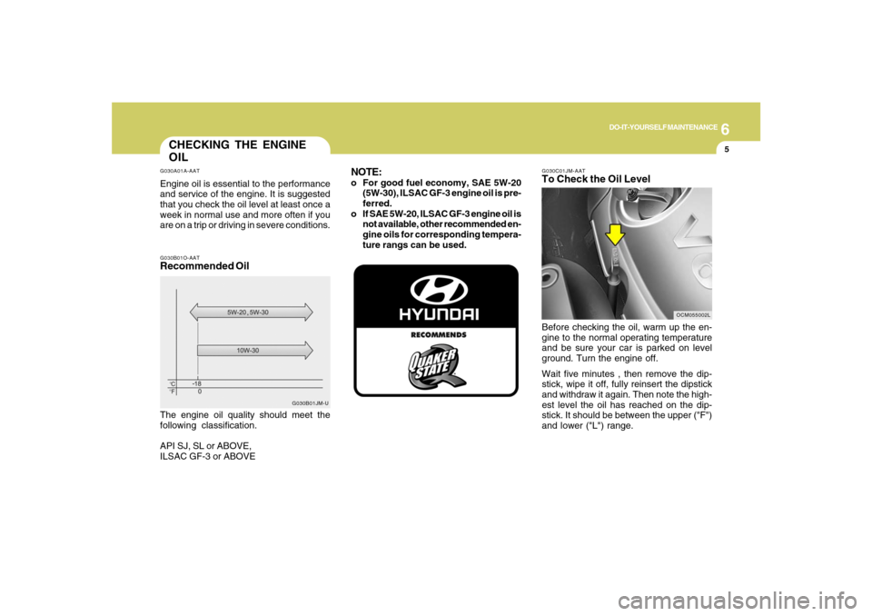
G030C01JM-AATTo Check the Oil LevelBefore checking the oil, warm up the en-
gine to the normal operating temperature
and be sure your car is parked on level
ground. Turn the engine off.
Wait five minutes , then remove the dip-
stick, wipe it off, fully reinsert the dipstick
and withdraw it again. Then note the high-
est level the oil has reached on the dip-
stick. It should be between the upper ("F")
and lower ("L") range.
OCM055002L G030B01O-AAT
Recommended OilThe engine oil quality should meet the
following classification.
API SJ, SL or ABOVE,
ILSAC GF-3 or ABOVE
G030B01JM-U
NOTE:o For good fuel economy, SAE 5W-20
(5W-30), ILSAC GF-3 engine oil is pre-
ferred.
o If SAE 5W-20, ILSAC GF-3 engine oil is
not available, other recommended en-
gine oils for corresponding tempera-
ture rangs can be used.
Page 299 of 355
6
DO-IT-YOURSELF MAINTENANCE
13
Keep the vehicle on level ground with the
parking brake applied and check the fluid
level according to the following proce-
dure.
1. Place the shift lever in N(neutral) posi-
tion and confirm the engine is running
at normal idle speed.
2. After the transaxle is warmed up suffi-
ciently [fluid temperature 70~80°C
(158~176°F)], for example by 10 min-
utes usual driving, move the shift lever
through all positions then place the shift
lever in N(neutral) or P(park) position.
OCM055037L
!
WARNING:
The cooling fan is controlled by engine
coolant temperature and may some-
times operate even when the engine is
not running. Use extreme caution when
working near the blades of the cooling
fan, so that you are not injured by a
rotating fan blade. As the engine coolant
temperature decreases, the fan will au-
tomatically shut off. This is a normal
condition.
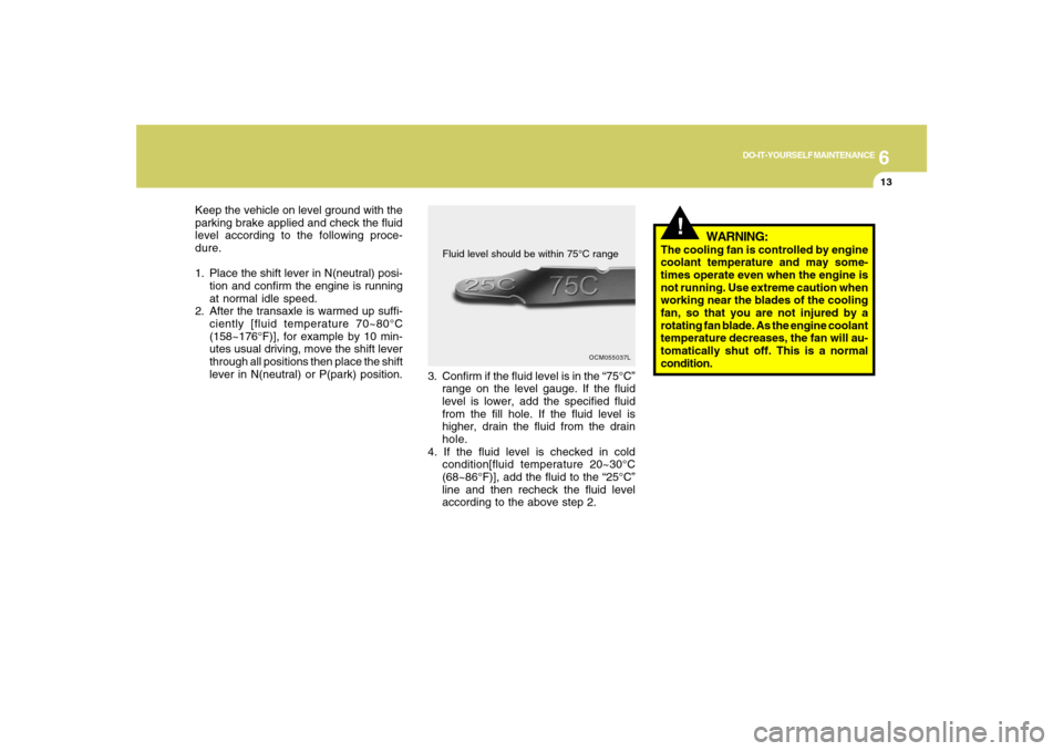
Fluid level should be within 75°C range
3. Confirm if the fluid level is in the “75°C”
range on the level gauge. If the fluid
level is lower, add the specified fluid
from the fill hole. If the fluid level is
higher, drain the fluid from the drain
hole.
4. If the fluid level is checked in cold
condition[fluid temperature 20~30°C
(68~86°F)], add the fluid to the “25°C”
line and then recheck the fluid level
according to the above step 2.
Page 302 of 355
6
DO-IT-YOURSELF MAINTENANCE
16
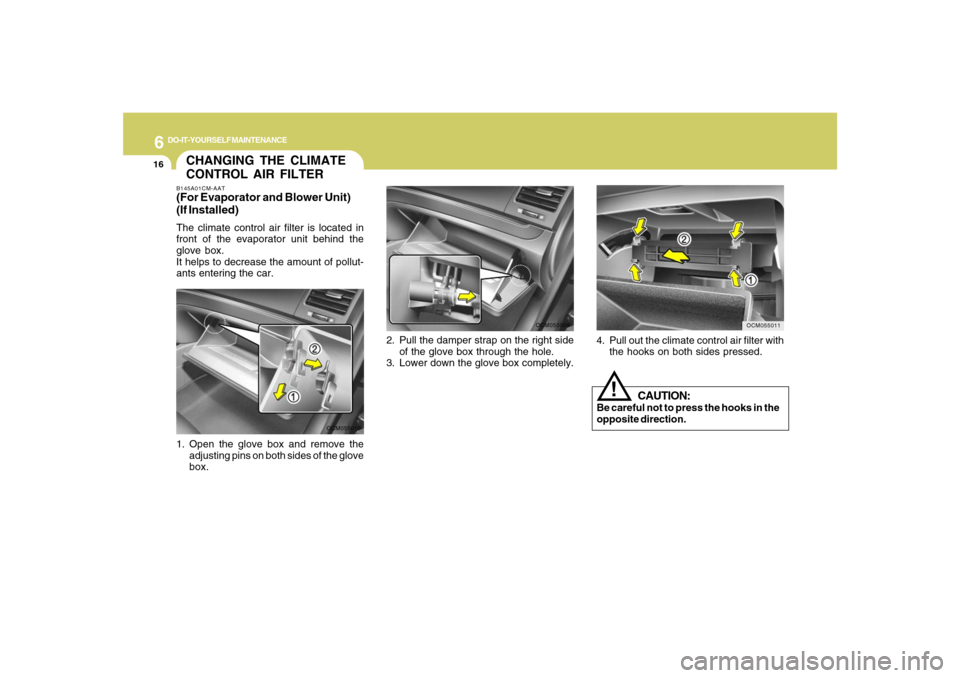
4. Pull out the climate control air filter with
the hooks on both sides pressed.
OCM055011
CHANGING THE CLIMATE
CONTROL AIR FILTERB145A01CM-AAT(For Evaporator and Blower Unit)
(If Installed)The climate control air filter is located in
front of the evaporator unit behind the
glove box.
It helps to decrease the amount of pollut-
ants entering the car.
1. Open the glove box and remove the
adjusting pins on both sides of the glove
box.
OCM055010
2. Pull the damper strap on the right side
of the glove box through the hole.
3. Lower down the glove box completely.
OCM055009
CAUTION:
Be careful not to press the hooks in the
opposite direction.
!
Page 304 of 355
6
DO-IT-YOURSELF MAINTENANCE
18
!
CAUTION:
When replacing a fusible link, never use
anything but a new fusible link with the
same or lower amperage rating. Never
use a piece of wire or a higher-rated
fusible link. This could result in serious
damage and create a fire hazard.
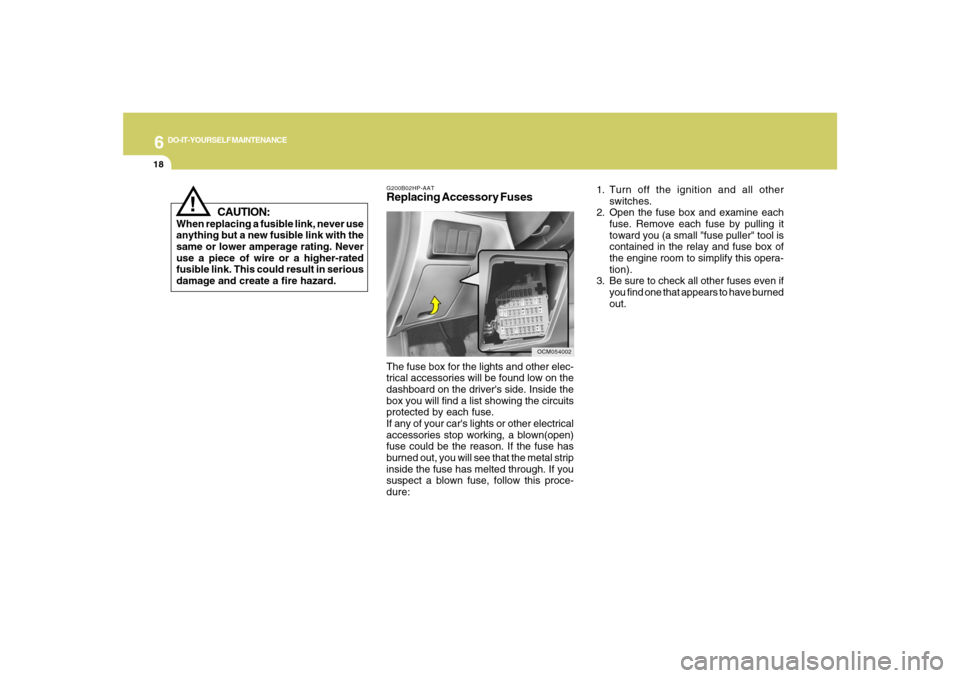
G200B02HP-AATReplacing Accessory Fuses
OCM054002
The fuse box for the lights and other elec-
trical accessories will be found low on the
dashboard on the driver's side. Inside the
box you will find a list showing the circuits
protected by each fuse.
If any of your car's lights or other electrical
accessories stop working, a blown(open)
fuse could be the reason. If the fuse has
burned out, you will see that the metal strip
inside the fuse has melted through. If you
suspect a blown fuse, follow this proce-
dure:1. Turn off the ignition and all other
switches.
2. Open the fuse box and examine each
fuse. Remove each fuse by pulling it
toward you (a small "fuse puller" tool is
contained in the relay and fuse box of
the engine room to simplify this opera-
tion).
3. Be sure to check all other fuses even if
you find one that appears to have burned
out.
Page 305 of 355
6
DO-IT-YOURSELF MAINTENANCE
19
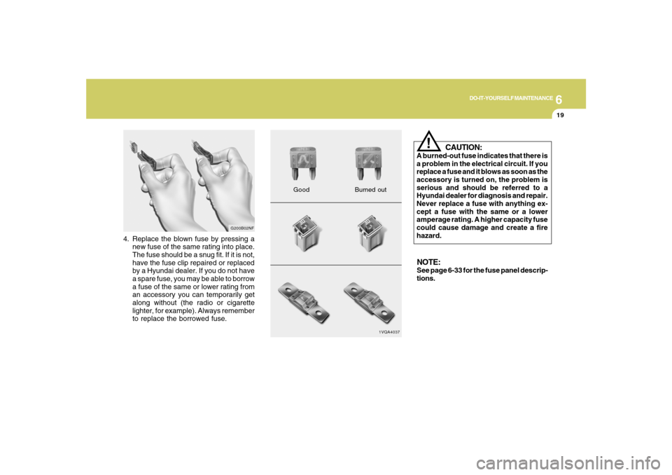
4. Replace the blown fuse by pressing a
new fuse of the same rating into place.
The fuse should be a snug fit. If it is not,
have the fuse clip repaired or replaced
by a Hyundai dealer. If you do not have
a spare fuse, you may be able to borrow
a fuse of the same or lower rating from
an accessory you can temporarily get
along without (the radio or cigarette
lighter, for example). Always remember
to replace the borrowed fuse.
G200B02NF
1VQA4037
GoodBurned out
CAUTION:
A burned-out fuse indicates that there is
a problem in the electrical circuit. If you
replace a fuse and it blows as soon as the
accessory is turned on, the problem is
serious and should be referred to a
Hyundai dealer for diagnosis and repair.
Never replace a fuse with anything ex-
cept a fuse with the same or a lower
amperage rating. A higher capacity fuse
could cause damage and create a fire
hazard.
!
NOTE:See page 6-33 for the fuse panel descrip-
tions.
Page 320 of 355

6
DO-IT-YOURSELF MAINTENANCE
34
G200E01CM-AATInner Panel
OCM055024N
FUSE RATING
15A
25A
15A
10A
15A
10A
10A
10A
30A
10A
15A
10A
10A
10A
10A
10A
10ACIRCUIT PROTECTED
CIGARETTE LIGHTER
FRONT POWER OUTLET, REAR POWER OUTLET
CENTER POWER OUTLET
POWER OUTSIDE MIRROR SWITCH, AUDIO, ATM KEY LOCK CONTROL MODULE,
DIGITAL CLOCK
MULTIFUNCTION SWITCH, REAR WIPER CONTROL MODULE,REAR WIPER
MOTOR
RAIN SENSOR
RHEOSTAT, BCM, INSTRUMENT CLUSTER
A/C CONTROL MODULE, INCAR & HUMIDITY SENSOR, HIGH BLOWER RELAY,
REAR A/CON SWITCH, ICM RELAY BOX, AQS SENSOR, SUNROOF MOTOR,
BLOWER BELAY, ELECTRO CHROMIC MIRROR
BLOWER RELAY, BLOWER MOTOR, A/C CONTROL MODULE
A/C CONTROL MODULE
SRS CONTROL MODULE
PAB ON/OFF SWITCH, INSTRUMENT CLUSTER
HAZARD SWITCH
MULTIFUNTION SWITCH, STEERING ANGLE SENSOR, ESC SWITCH, ATM KEY
LOCK CONTROL MODULE SEAT WARMER MODULE
OIL LEVEL SENSOR MODULE, BCM
INSTRUMENT CLUSTER, PRE-EXCITATION RESISTOR, BCM, GENERATOR, SEMI
ACTIVE CONTROL MODULE (GASOLINE)
BURGLAR ALARM RELAY
C/LIGHTER
P/OUTLET
P/OUTLET
CTR
AUDIO #2
RR WIPER
IMS
BCM #2
A/CON 2
BLOWER
A/CON 1
A/BAG #1
A/BAG IND
T/SIG
ATM LOCK
BCM #1
CLUSTER
STARTFUSE
Page 351 of 355
10
INDEX
4
Air intake control switch ............................................................1-126
Bi-level heating..........................................................................1-128
Defrosting / Defogging ..............................................................1-133
Fan speed control (Blower control)..........................................1-126
Temperature control.................................................................1-130
High-Mounted Rear Stop Light ......................................................1-112
Hood Release.................................................................................1-115
Horn..............................................................................................1-119
I
Ignition Switch ...................................................................................... 2-5
Instrument Cluster and Indicator Lights...........................................1-62
Instrument Panel Light Control (Rheostat).......................................1-84
Interior Light.......................................................................................1-93
J
Jump Starting...................................................................................... 3-3
K
Keys................................................................................................... 1-3
If you lose your keys ...................................................................3-21
Positions......................................................................................... 2-5
L
Light Bulbs Replacement ..................................................................6-24
Luggage Compartment ..................................................................1-109
Cargo security screen ..............................................................1-109
Luggage Net ..............................................................................1-110
Luggage under tray ...................................................................1-111M
Maintenance Intervals
Explanation of scheduled maintenance items ............................... 5-7
Maintenance under severe usage conditions............................... 5-6
Scheduled maintenance................................................................ 5-4
Service requirements.................................................................... 5-2
Mirrors
Automatic Dimming Rear View Mirror With Compass .............1-100
Day-night inside rearview mirror .................................................1-99
Homelink mirror.........................................................................1-102
Outside rearview mirror ...............................................................1-97
Outside rearview mirror Heater ..................................................1-98
O
Odometer / Trip Odometer ...............................................................1-71
Occupant Classification System ......................................................1-52
P
Parking Brake.................................................................................
1-108
Power Outlet......................................................................................1-86
Power Steering Fluid Level ...............................................................6-23
R
Rear Seat
Adjusting seatback angle .............................................................1-22
Folding rear seatback ..................................................................1-23
Rear Window Defroster Switch ........................................................1-88
Reporting Safety Defects .................................................................8-17
Risk of Rollover................................................................................... 2-3
Roof Rack......................................................................................1-111