2008 GREAT WALL FLORID suspension
[x] Cancel search: suspensionPage 5 of 281

Downloaded from www.Manualslib.com manuals search engine Chapter Five: Transmission ........................................................................\
................................42
037A Transmission’s Overall External Schematics ....................................................43
Main Technical Parameters ..................................................................................\
....43
Transmission’s Proper Use and Care ........................................................................44
Technical Specifications for Transmission Installation and Adjustment .....................44
Areas of Importance ..................................................................................\
................45
Troubleshooting ..................................................................................\
.......................46
037A Transmission Structural Schematics ................................................................47
Clutch ...................................................................................\
......................................48
Gear Shift Fork and Fork Shaft ..................................................................................49
Transmission Case ..................................................................................\
..................50
Disassembling the Input Shaft Subassembly ............................................................56
Disassembling the Output Shaft Subassembly ..........................................................60
Disassembling the Shift Cover Subassembly ............................................................64
Disassembling the Differential Subassembly .............................................................68
Chapter Six: Suspension System ........................................................................\
.......................71
Suspension System Technical Parameters ...............................................................72
Front Suspension ...................................................................................\
....................73
Subframe and Front Stabilizer Bar ............................................................................77
Lower Swing Arm ...................................................................................\
....................80
Drive Shaft ..................................................................................\
...............................84
Rear Suspension ..................................................................................\
.....................86
Wheel and Tire ...................................................................................\
........................89
Chapter Seven: Brake System ........................................................................\
...........................94
Brake System Components Arrangement Schematics ..............................................95
Brake System Maintenance ...................................................................................\
....96
Brake Pedal ..................................................................................\
.............................98
Parking Brake Control Mechanism Assembly ..........................................................102
Vacuum Booster with Brake Cylinder Assembly ......................................................103
Anti-lock Brake System ...................................................................................\
.........107
ABS General Problem Maintenance and Areas of Importance ................................109
Steering Knuckle and Hub Brake Assembly ............................................................112
Front Brake Caliper ...................................................................................\
...............118
Rear Brake ...................................................................................\
............................124
Rear Support Axle ...................................................................................\
.................131
Chapter Eight: Steering System ........................................................................\
.......................134
Troubleshooting ..................................................................................\
.....................135
Steering System Maintenance .................................................................................137
Power Steering Fluid Instructions ............................................................................141
Page 18 of 281

Downloaded from www.Manualslib.com manuals search engine 11Overall Parameters
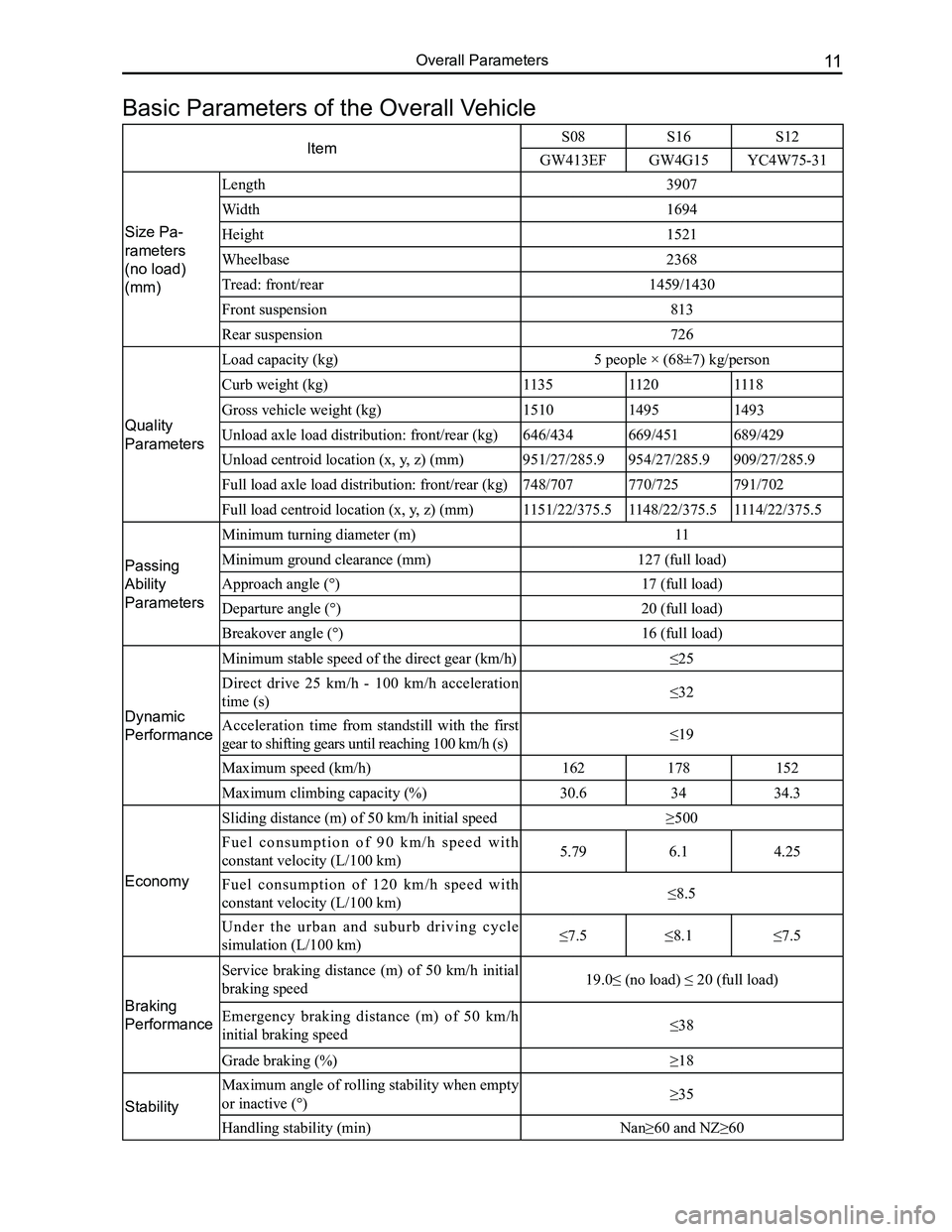
ItemS08 S16S12
GW413EFGW4G15YC4W75-31
Size Pa-
rameters
(no load)
(mm)
Length3907
Width1694
Height1521
Wheelbase2368
Tread: front/rear1459/1430
Front suspension813
Rear suspension726
Quality
Parameters
Load capacity (kg)5 people × (68±7) kg/person
Curb weight (kg)113511201118
Gross vehicle weight (kg)151014951493
Unload axle load distribution: front/rear (kg)646/434669/451689/429
Unload centroid location (x, y, z) (mm)951/27/285.9954/27/285.9909/27/285.9
Full load axle load distribution: front/rear (kg)748/707770/725791/702
Full load centroid location (x, y, z) (mm)1151/22/375.51148/22/375.51114/22/375.5
Passing
Ability
Parameters
Minimum turning diameter (m)11
Minimum ground clearance (mm)127 (full load)
Approach angle (°)17 (full load)
Departure angle (°)20 (full load)
Breakover angle (°)16 (full load)
Dynamic
Performance
Minimum stable speed of the direct gear (km/h)≤25
Direct drive 25 km/h - 100 km/h acceleration
time (s)≤32
Acceleration time from standstill with the first
gear to shifting gears until reaching 100 km/h (s)≤19
Maximum speed (km/h)162178152
Maximum climbing capacity (%)30.63434.3
Economy
Sliding distance (m) of 50 km/h initial speed≥500
F u e l c o n s u m p t i o n o f 9 0 k m / h s p e e d w i t h
constant velocity (L/100 km)5.796.14.25
Fuel consumption of 120 km/h speed with
constant velocity (L/100 km)≤8.5
U n d e r t h e u r b a n a n d s u b u r b d r i v i n g c y c l e
simulation (L/100 km)≤7.5≤8.1≤7.5
Braking
Performance
Service braking distance (m) of 50 km/h initial
braking speed19.0≤ (no load) ≤ 20 (full load)
Emergency braking distance (m) of 50 km/h
initial braking speed ≤38
Grade braking (%)≥18
Stability
Maximum angle of rolling stability when empty
or inactive (°)≥35
Handling stability (min)Nan≥60 and NZ≥60
Basic Parameters of the Overall Vehicle
Page 78 of 281

Downloaded from www.Manualslib.com manuals search engine 71Suspension System
Suspension System
Suspension System Technical Parameters ........................72
Front Suspension ...............................................................73
Subframe and Front Stabilizer Bar .....................................77
Lower Swing Arm................................................................80
Drive Shaft ........................................................................\
..84
Rear Suspension ................................................................86
Wheel and Tire ...................................................................89
Page 79 of 281

Downloaded from www.Manualslib.com manuals search engine GWFLORID Maintenance Manual72
Suspension System Technical Parameters
Main technical parameters
Suspension type and
composition
Front suspension typeMcPherson independent suspension
Front suspension componentsCoil spring, hydraulic telescopic shock absorber, stabilizer bar, lower swing
arm
Rear suspension typeCompound trailing arm semi-independent suspension
Rear suspension componentsCoil spring, hydraulic cylinder damper, & twist beam welded components
Wheel positional
parameters
(no load)
Front wheel camber-0° 43′ ±30′
Front wheel kingpin angle+10° 21′ ±30′
Front wheel kingpin caster+1° 49′ ±30′
Front wheel toe-in-0° 01′ ±15′
Rear wheel camber-0° 43′ ±30′
Rear wheel toe-in+0° 14′ ±15′
Wheel and tire parameters
Tire specifications: 15 × 6J (For 185/65R15 tires), 16 × 4T (For T125/70R16 tires)
Tire specification: 185/65 R15 88H
Spare tire specification: T125/70R16 96M
Tire pressure must be gauged when the tire is cool: Tire inflation pressure: 200±10 KPa
Spare tir e inflation pressure: 420±10 KPa
Tightening torque
PartCodeAssembly locations for
standard components
Tightening
torque
(N·m)
QuantityGlueGrade
Front
suspen-
sion
Q1861455TF2
(M14×1.5) + Q402
(d2=32 t=5) FD
Subframe & vehicle body (rear)145±15 2Red glue10.9
Q1861275TF2
(M12×1.25) + Q402
(d2=32) FD
Subframe & vehicle body (front)120±102Red glue10.9
Q1401020 (M10×1.25) FDSubframe strut bar mounting bolt49±54Red glue10.9
2904011-S08Swing arm & steering knuckle98±102Red glue
Q1401495 (t=4)
(M14×1.5) FDSwing arm & subframe (front)180±102Red glue10.9
Q1401280 (M12×1.25) FDSwing arm & subframe (rear)120±102Red glue10.9
2904013-S08Swing arm & subframe (rear)/2
2905011-S08Front shock upper assembly loca-
tion40±56
Q32014 (M14×1.5) FDFront shock lower assembly loca-
tion132±104Red glue10.9
Q1400830 (d2=13.5)F r o n t s t a b i l i z e r b a r m o u n t i n g
bracket37±44Red glue
Q32608Front stabilizer bar hanger rod16±24
Rear sus-
pension
Q151B12110TF2+Q402
(d2=35 t=5) FDTwist beam & vehicle body80±102Red glue10.9 grade
with guide
Q32012T13F2
(M12×1.25) FDRear shock absorber & twist beam120±102Red glue10 grade
Q341C10Rear shock absorber & vehicle
body64±54
Wheel3101014-K00Wheel nut (M12×1.25)110±1016
Q30612FD (M12×1.25)Wheel nut cone nut110±1016
Page 80 of 281

Downloaded from www.Manualslib.com manuals search engine 73Suspension System
Steering knuckle assembly removal
1. Preparation
First, remove the front wheel, the front shock absorber with
coil spring assembly, and the steering knuckle coupling
bolt in turn. For detailed steps, please refer to the removal
of the wheel and the front shock absorber with coil spring
assembly.
2. Remove propeller shaft nuts
(a) First, pry the flattened areas of the propeller shaft's nuts
into a circle with a chisel.
(b) Half-insert a long bolt or metal bar into the brake disc
holes to loosen the nuts (shown on the left).
Tightening torque: 225±20 N·m
Front Suspension
Components
(c) Pull out the mount point on the steering knuckle to
separate it from the mounting bracket under the front
shock absorber. Prop a wood stick or metal bar against
the propeller shaft's outer end, and then hammer the
stick or metal bar to get the propeller shaft out of the
hub (shown on the left).
Caution: When hammering, prop it up against the shaft
end's location holes (middle recess). Be sure not to
damage the thread.
Insert into this hole
Press plate on the front shock absorber column
Front shock absorber with coil spring assembly
Front stabilizer bar mounting bracket
Front stabilizer bar bushing
Front stabilizer bar
Lower swing arm assembly RH
Lower swing arm assembly LH
Subframe assembly
Front stabilizer bar hanger rod subassembly
Subframe strut bar
Page 82 of 281

Downloaded from www.Manualslib.com manuals search engine 75Suspension System
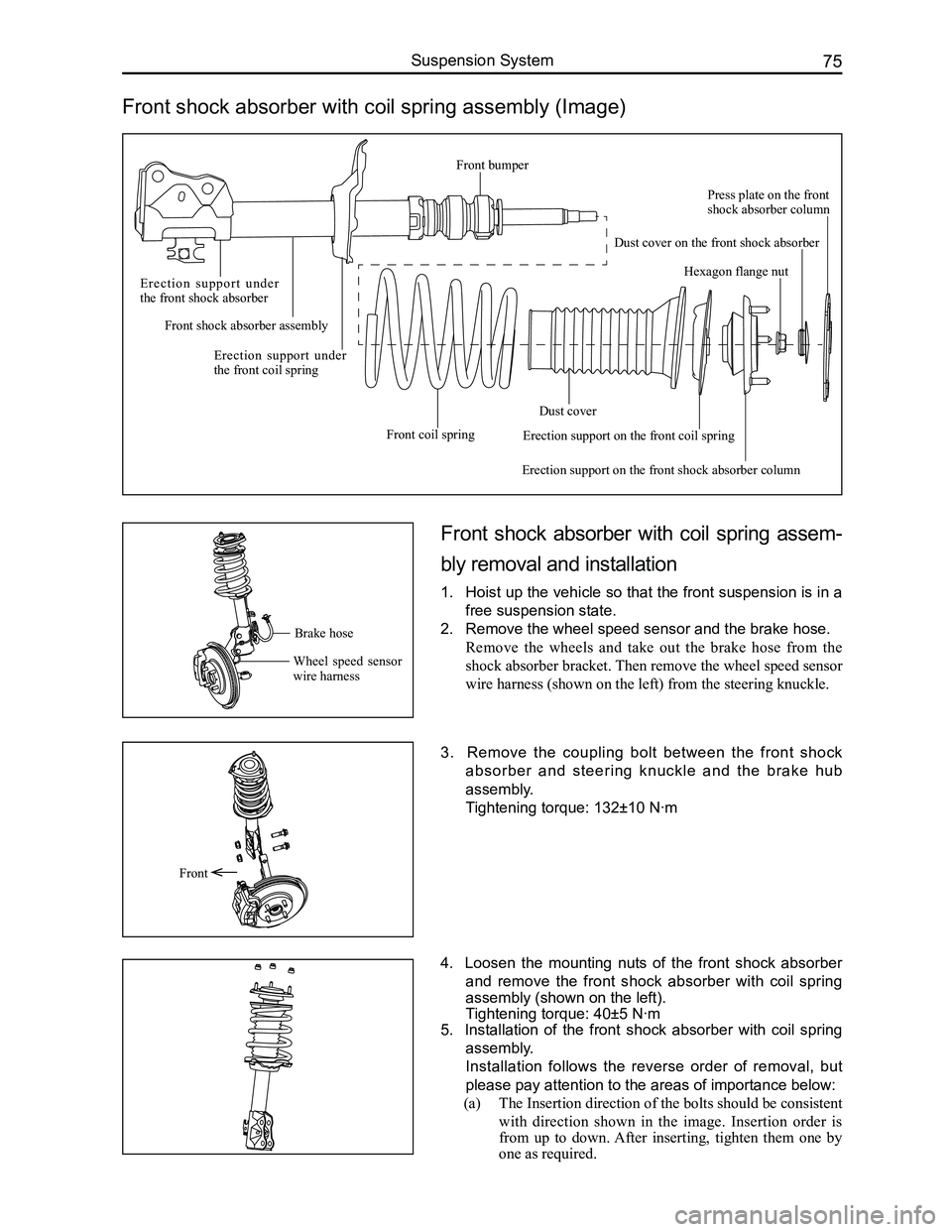
Front shock absorber with coil spring assembly (Image)
Front shock absorber with coil spring assem-
bly removal and installation
1. Hoist up the vehicle so that the front suspension is in a
free suspension state.
2. Remove the wheel speed sensor and the brake hose.
Remove the wheels and take out the brake hose from the
shock absorber bracket. Then remove the wheel speed sensor
wire harness (shown on the left) from the steering knuckle.
3. Remove the coupling bolt between the front shock
absorber and steering knuckle and the brake hub
assembly.
Tightening torque: 132±10 N·m
4. Loosen the mounting nuts of the front shock absorber
and remove the front shock absorber with coil spring
assembly (shown on the left).
Tightening torque: 40±5 N·m
5. Installation of the front shock absorber with coil spring
assembly.
Installation follows the reverse order of removal, but
please pay attention to the areas of importance below:
(a) The Insertion direction of the bolts should be consistent
with direction shown in the image. Insertion order is
from up to down. After inserting, tighten them one by
one as required.
Front
Brake hose
Wheel speed sensor wire harness
E r e c t i o n s u p p o r t u n d e r the front shock absorber
Front shock absorber assembly
Erection support under the front coil spring
Front coil spring
Dust cover
Erection support on the front shock absorber column
Hexagon flange nut
Press plate on the front shock absorber column
Dust cover on the front shock absorber
Erection support on the front coil spring
Front bumper
Page 84 of 281

Downloaded from www.Manualslib.com manuals search engine 77Suspension System
Subframe and Front Stabilizer Bar
Components
Front stabilizer bar
Lower swing arm RH
Subframe
Subframe strut bar
Lower swing arm LH
Stabilizer bar bracket
Stabilizer bar bushing
Subframe removal and installation
1. Remove the engine's rear suspension bolts, coupling
bolts between steering propeller shaft and column,
and the steering fuel hose. Disconnect the connection
between the steering knuckle, swing arm, and steering
tie rod. For detailed steps, please refer to the removal
o f t h e e n g i n e , s t e e r i n g s y s t e m , a n d t h e s t e e r i n g
knuckle assembly.
2. Remove the strut bar.
Screw off the subframe strut bar mounting bolts Q1401020
(M10×1.25) FD with a sleeve, and remove the strut bar. As
shown on the left: There are four bolts, two on the left and
two on the right.
Tightening torque: 49±5 N·m
Caution: When removing the steering fuel hose, power
steering fluid may flow out, so collect the fluid in a
container.
3. Remove subframe.
Remove the subframe's front mounting bolt Q1861275TF2
(M12×1.25) + Q402 (d2=32) FD with a M18 sleeve (needs
a extension bar). Remove the subframe's rear mounting bolt
Q1861455TF2 (M14×1.5) + Q402 (d2=32 t=5) FD with the
same tool. (shown on the left).
Caution: Lift the subframe when removing to avoid
operator injury due to it falling off.
4. Remove the front stabilizer bar, steering gear, and
lower swing arm. For detailed steps, please refer to the
removal and installation of the stabilizer bar, steering
gear, and lower swing arm.
Q1401020
Q1861275TF2
Q1861455TF2
Page 86 of 281

Downloaded from www.Manualslib.com manuals search engine 79Suspension System
(b) The sliding side of the hanger rod should face upward,
so as to make the operation more convenient. CorrectIncorrect