2008 GREAT WALL FLORID wheel bolt torque
[x] Cancel search: wheel bolt torquePage 119 of 281

Downloaded from www.Manualslib.com manuals search engine GWFLORID Maintenance Manual112
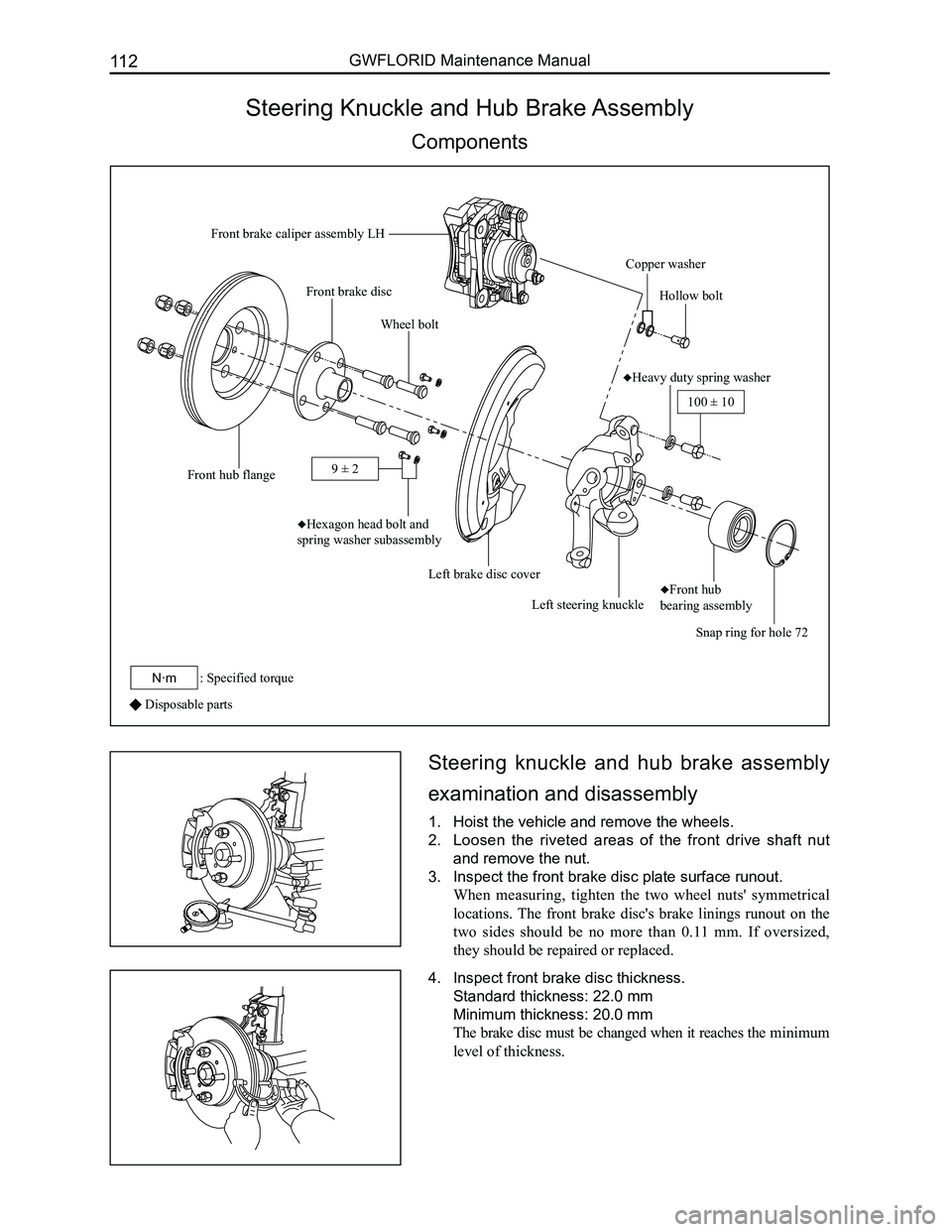
Steering Knuckle and Hub Brake Assembly
Components
Disposable parts
Steering knuckle and hub brake assembly
examination and disassembly
1. Hoist the vehicle and remove the wheels.
2. Loosen the riveted areas of the front drive shaft nut
and remove the nut.
3. Inspect the front brake disc plate surface runout.
When measuring, tighten the two wheel nuts' symmetrical
locations. The front brake disc's brake linings runout on the
two sides should be no more than 0.11 mm. If oversized,
they should be repaired or replaced.
4. Inspect front brake disc thickness.
Standard thickness: 22.0 mm
Minimum thickness: 20.0 mm
The brake disc must be changed when it reaches the minimum
level of thickness.
Front brake caliper assembly LH
Copper washer
Hollow bolt
♦Heavy duty spring washer
Snap ring for hole 72
♦Front hub
bearing assemblyLeft steering knuckle
Left brake disc cover
♦Hexagon head bolt and
spring washer subassembly
Wheel bolt
Front hub flange
Front brake disc
100 ± 10
: Specified torqueN·m
9 ± 2
Page 121 of 281

Downloaded from www.Manualslib.com manuals search engine GWFLORID Maintenance Manual114
(d) Measure the front hub bearing's starting torque.
Put the SST on the wheel bolts which are at the symmetric
locations. Put a dial torque wrench on the SST to slowly
rotate the flange assembly (45°/4s), requiring a starting
torque range of 0.1-0.3 N·m.
If the bearing rotation is not flexible, the front hub flange
plate surface movement inaccurate, or front hub bearing
starting torque is too much. The assembly must be replaced.
Steering knuckle's front hub bearing and
front hub flange assembly
1. Removal and inspection of front hub flange assembly.
(a) Use SST like a hand held travel hammer to repeatedly
hammer off the front hub flange assembly from the
steering knuckle and front hub bearing. Remove the
front hub with bearing's inner ring.
(b) Remove the bearing's inner ring on the front hub.
Use SST to remove the bearing's inner ring.
SST
SST
Bearing inner ring
SST
(c) Use dye penetrant to inspect the front hub flange for
cracks, which should be replaced if found.
(d) If one would like to continue using the front hub flange
assembly, first inspect the dimensions for the mounting
area of the bearing for inaccurate dimensions. If
oversized, replace.
Measurement range: Φ38+0.025 +0.009 mm
2. Remove the steering knuckle's front hub bearing.
3. Remove the snap ring for hole 72.
Use a bent nose retaining ring caliper for holes to remove the
snap ring for hole 72.
Page 123 of 281

Downloaded from www.Manualslib.com manuals search engine GWFLORID Maintenance Manual116
3. Examine the front hub flange plate surface runout.
Examining methods are the same as the methods used
during disassembly. Plate surface runout should not exceed
0.03 mm.
4. Examine the front hub bearing assembly's starting
torque.
Examining methods are the same as the methods used during
disassembly. Put the SST on the wheel bolts which are at the
symmetrical locations. Put a dial torque wrench on the SST to
slowly rotate the flange's flange assembly (45°/4s), which re-
quires a starting torque range of 0.1-0.3 N·m
5. Install the snap ring for hole 72.
Use a bent nose retaining ring caliper for holes to install the
snap ring for hole 72 at the steering knuckle's retaining ring
mounting position.
6. Install the steering knuckle's front hub bearing and
front hub flange assembly.
7. Install the front brake disc cover.
Install the front brake disc cover on the steering knuckle, and
tighten the bolt to the set torque.
Tightening torque: 9±2 N·m
SST
8. Install the front brake disc.
Page 124 of 281

Downloaded from www.Manualslib.com manuals search engine 117Brake System
9. Examine the front brake disc plate surface runout.
When measuring, tighten the two wheel nut's symmetrical
locations. The front brake disc's brake linings runout on the
two sides should be less than 0.11 mm.
10. Install the brake caliper assembly.
Install the brake caliper on the steering knuckle, and tighten
the bolt according to the set torque.
Tightening torque: 100±10 N·m
Page 127 of 281

Downloaded from www.Manualslib.com manuals search engine GWFLORID Maintenance Manual120
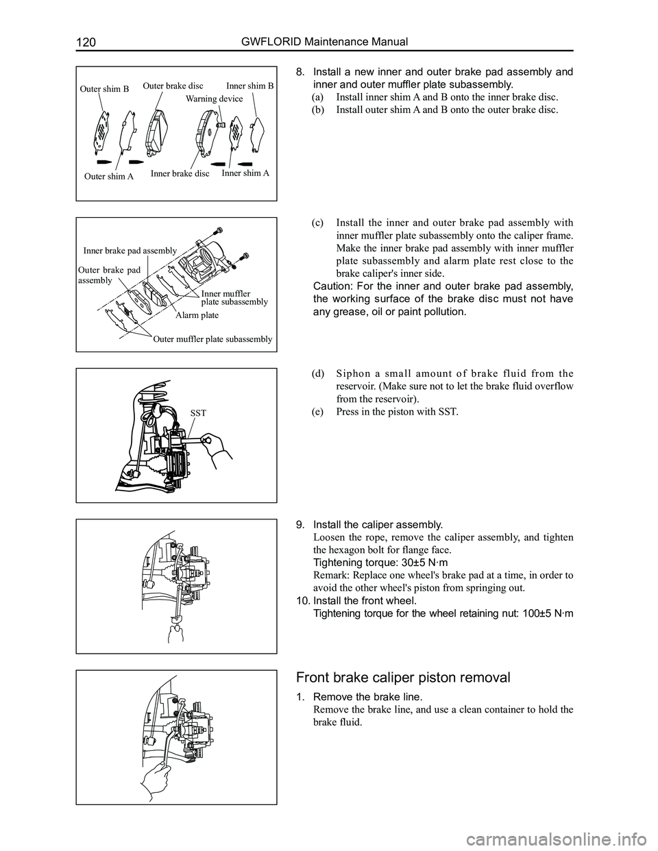
8. Install a new inner and outer brake pad assembly and
inner and outer muffler plate subassembly.
(a) Install inner shim A and B onto the inner brake disc.
(b) Install outer shim A and B onto the outer brake disc.
(c) Install the inner and outer brake pad assembly with
inner muffler plate subassembly onto the caliper frame.
Make the inner brake pad assembly with inner muffler
plate subassembly and alarm plate rest close to the
brake caliper's inner side.
Caution: For the inner and outer brake pad assembly,
the working surface of the brake disc must not have
any grease, oil or paint pollution.
(d) S i p h o n a s m a l l a m o u n t o f b r a k e f l u i d f r o m t h e
reservoir. (Make sure not to let the brake fluid overflow
from the reservoir).
(e) Press in the piston with SST.
9. Install the caliper assembly.
Loosen the rope, remove the caliper assembly, and tighten
the hexagon bolt for flange face.
Tightening torque: 30±5 N·m
Remark: Replace one wheel's brake pad at a time, in order to
avoid the other wheel's piston from springing out.
10. Install the front wheel.
Tightening torque for the wheel retaining nut: 100±5 N·m
Front brake caliper piston removal
1. Remove the brake line.
Remove the brake line, and use a clean container to hold the
brake fluid.
SST
Outer shim B
Outer shim AInner brake disc
Warning device
Inner shim B
Inner shim A
Outer brake disc
Inner muffler plate subassembly
Alarm plate
Inner brake pad assembly
Outer brake pad assembly
Outer muffler plate subassembly
Page 135 of 281

Downloaded from www.Manualslib.com manuals search engine GWFLORID Maintenance Manual128
Rear Brake Installation
1. Install the brake wheel cylinder.
(a) Apply a small amount of lithium grease onto two piston
assemblies.
(b) Install the wheel cylinder assembly.
• Install two dust covers onto the two piston assemblies.
• Install a piston spring and two piston components in the
wheel cylinder body.
R e m a r k : R e f e r t o t h e d i a g r a m f o r p r e c i s e i n s t a l l a t i o n
directions.
2. Install the wheel cylinder assembly.
(a) Use two bolts to install the wheel cylinder assembly
onto the brake back plate assembly.
Tightening torque: 7.8-11.8 N·m
(b) Connect the brake line to the wheel cylinder assembly.
Tightening torque: 16 N·m
3. Apply an appropriate amount of grease to the following
parts.
(a) Apply a small amount of high temperature resistant
grease on the brake back plate assembly and the brake
shoe connection's six convex plate surface.
Caution: Refer to the diagram for installation directions.
ForewardForeward
Left wheelRight wheel
Page 138 of 281

Downloaded from www.Manualslib.com manuals search engine 131Brake System
Rear Support Axle
Components
Rear hub unit inspection and removal
1. Manually rotate the wheel according to the diagram,
and check the bearing of the rear hub unit for abnormal
noises and stiff rotation. If these flaws exist, please
replace the rear hub unit.
2. Remove the wheel.
3. Manually screw the two wheel nut's opposite angles on the
wheel bolt and fixed rear brake drum.
Remark: Alternately tighten the two nuts, and manually
screw it down as much as possible.
Rear brake drum
Rear brake assembly RH
R i g h t p a r k i n g b r a k e cable assembly
Rear hub unit
Trailing arm spindle sleeve with nylon bushing assembly
Rear twist beam assembly
Rear brake assembly LH
Rear brake drum
Rear hub unit
Left parking brake cable assembly
Disposable parts
Spring
Spring
9±1
: Specified torqueN·m
78-98
9±1
100
100
Page 142 of 281

Downloaded from www.Manualslib.com manuals search engine 135Steering System
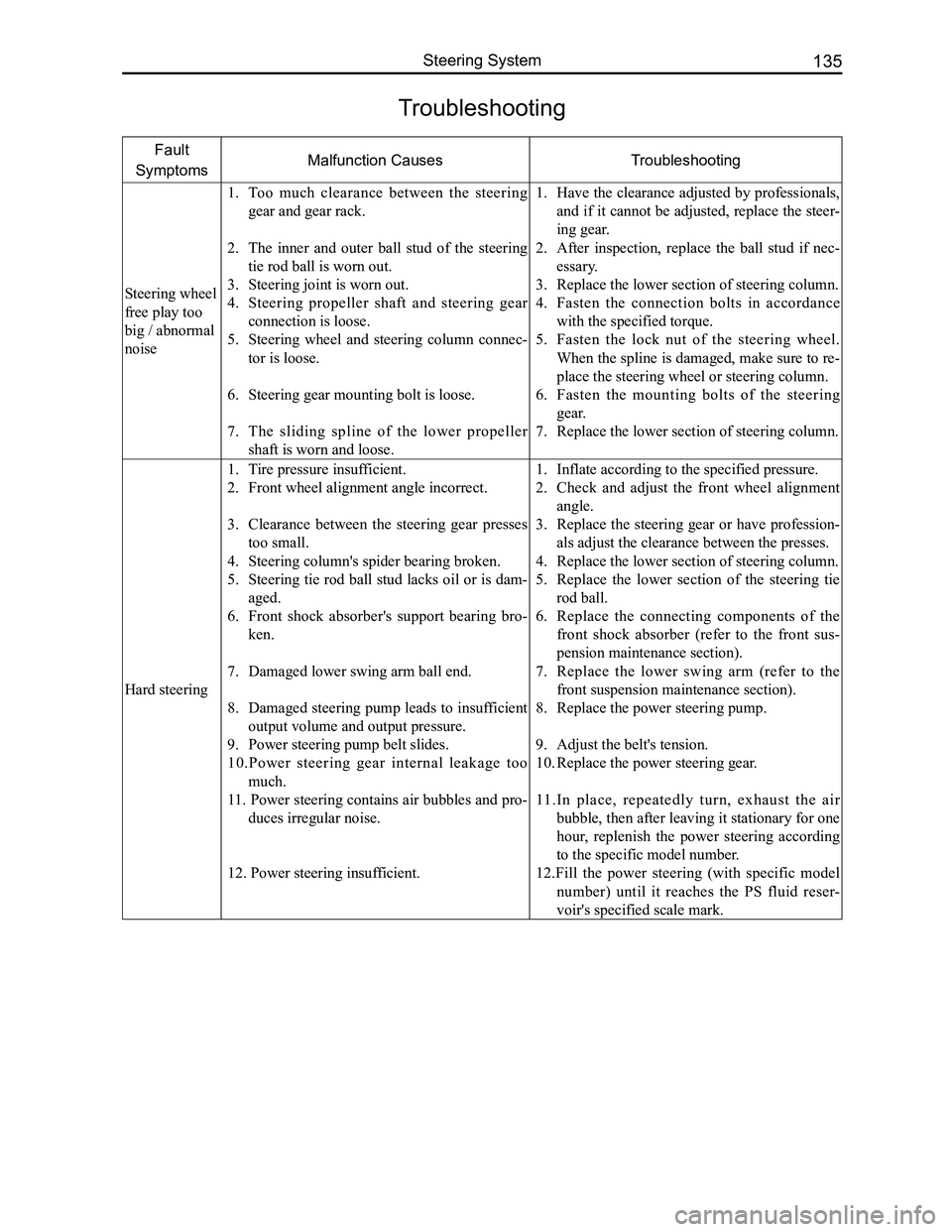
Troubleshooting
Fault
SymptomsMalfunction CausesTroubleshooting
Steering wheel
free play too
big / abnormal
noise
1. Too much clearance between the steering
gear and gear rack.
2. The inner and outer ball stud of the steering
tie rod ball is worn out.
3. Steering joint is worn out.
4. Steering propeller shaft and steering gear
connection is loose.
5. Steering wheel and steering column connec-
tor is loose.
6. Steering gear mounting bolt is loose.
7. The sliding spline of the lower propeller
shaft is worn and loose.
1. Have the clearance adjusted by professionals,
and if it cannot be adjusted, replace the steer-
ing gear.
2. After inspection, replace the ball stud if nec-
essary.
3. Replace the lower section of steering column.
4. Fasten the connection bolts in accordance
with the specified torque.
5. Fasten the lock nut of the steering wheel.
When the spline is damaged, make sure to re-
place the steering wheel or steering column.
6. Fasten the mounting bolts of the steering
gear.
7. Replace the lower section of steering column.
Hard steering
1. Tire pressure insufficient.
2. Front wheel alignment angle incorrect.
3. Clearance between the steering gear presses
too small.
4. Steering column's spider bearing broken.
5. Steering tie rod ball stud lacks oil or is dam-
aged.
6. Front shock absorber's support bearing bro-
ken.
7. Damaged lower swing arm ball end.
8. Damaged steering pump leads to insufficient
output volume and output pressure.
9. Power steering pump belt slides.
10.Power steering gear internal leakage too
much.
11. Power steering contains air bubbles and pro-
duces irregular noise.
12. Power steering insufficient.
1. Inflate according to the specified pressure.
2. Check and adjust the front wheel alignment
angle.
3. Replace the steering gear or have profession-
als adjust the clearance between the presses.
4. Replace the lower section of steering column.
5. Replace the lower section of the steering tie
rod ball.
6. Replace the connecting components of the
front shock absorber (refer to the front sus-
pension maintenance section).
7. Replace the lower swing arm (refer to the
front suspension maintenance section).
8. Replace the power steering pump.
9. Adjust the belt's tension.
10. Replace the power steering gear.
11.In place, repeatedly turn, exhaust the air
bubble, then after leaving it stationary for one
hour, replenish the power steering according
to the specific model number.
12.Fill the power steering (with specific model
number) until it reaches the PS fluid reser-
voir's specified scale mark.