Page 175 of 416

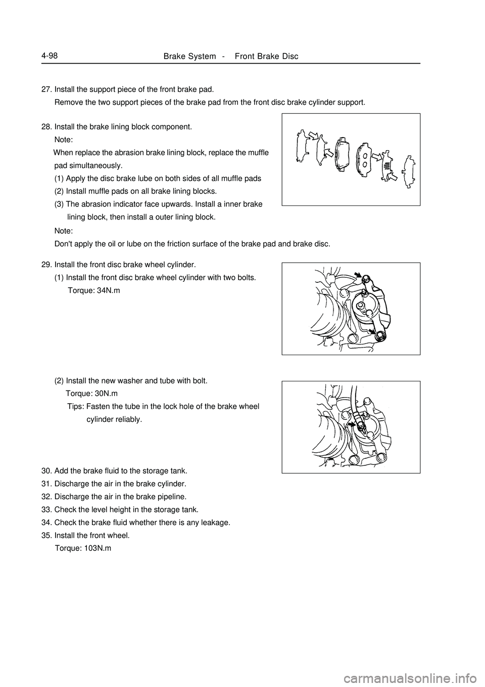
Brake System -Front Brake Disc4-9827. Install the support piece of the front brake pad.
Remove the two support pieces of the brake pad from the front disc brake cylinder support.
28. Install the brake lining block component.
Note:
When replace the abrasion brake lining block, replace the muffle
pad simultaneously.
(1) Apply the disc brake lube on both sides of all muffle pads
(2) Install muffle pads on all brake lining blocks.
(3) The abrasion indicator face upwards. Install a inner brake
lining block, then install a outer lining block.
Note:
Don't apply the oil or lube on the friction surface of the brake pad and brake disc.
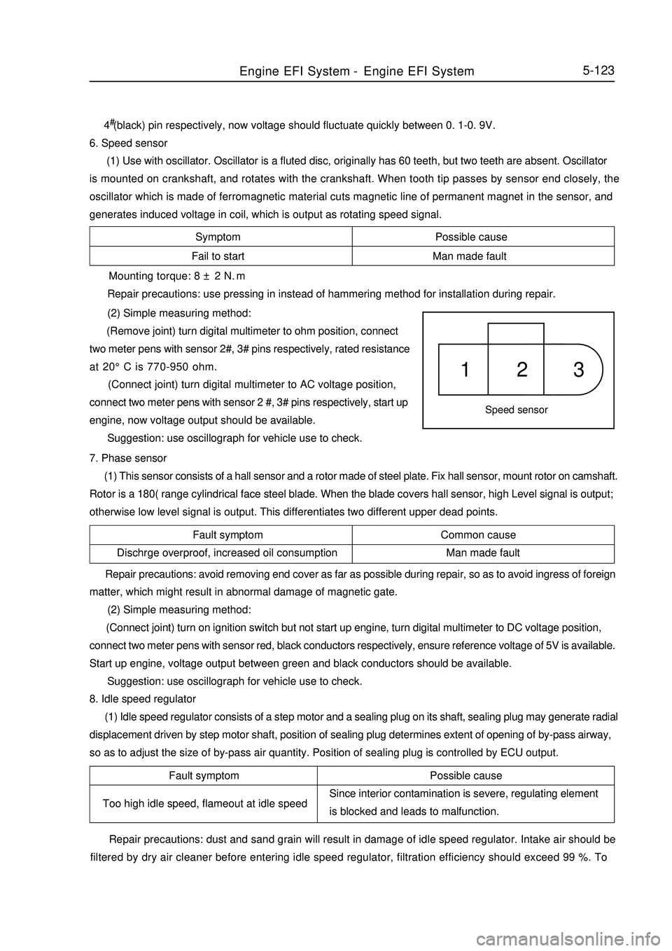
29. Install the front disc brake wheel cylinder.
(1) Install the front disc brake wheel cylinder with two bolts.
Torque: 34N.m
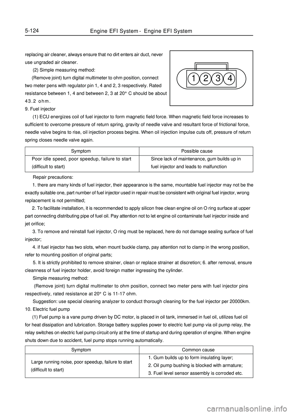
(2) Install the new washer and tube with bolt.
Torque: 30N.m
Tips: Fasten the tube in the lock hole of the brake wheel
cylinder reliably.
30. Add the brake fluid to the storage tank.
31. Discharge the air in the brake cylinder.
32. Discharge the air in the brake pipeline.
33. Check the level height in the storage tank.
34. Check the brake fluid whether there is any leakage.
35. Install the front wheel.
Torque: 103N.m
Page 182 of 416
Brake System -Rear Brake Drum4-105 (2) Measure the inner diameter of the brake drum and the
diameter of the brake shoe, and check the difference of them
whether it is a proper brake shoe clearance.
Brake Shoe Clearance: 0.3mm
Note:
Don't apply the oil or lube on the friction surface of the brake shoe
lining and brake drum.
30. Adjust the shoe clearance of the brake drum.
(1) Install two wheel hub nuts temporarily.
(2) Turn around eight teeth of the adjustor.
(3) Install the hole plug.
31. Install the rear brake drum sub-assembly.
32. Add the brake fluid to the storage tank.
33. Discharge the air in the master cylinder.
34. Discharge the air in the brake pipeline.
35. Check the level height in the storage tank.
36. Check the brake fluid whether there is any leakage.
37. Install the rear wheel.
Torque: 103N.m
38. Check the stroke of the parking brake extension rod.
39. Adjust he stroke of the parking brake extension rod.Extend
Page 310 of 416

Symptom Possible cause
Fail to start Man made faultSpeed sensor1 2 3Fault symptom Common cause
Dischrge overproof, increased oil consumption Man made fault5-1234#(black) pin respectively, now voltage should fluctuate quickly between 0. 1-0. 9V.
6. Speed sensor
(1) Use with oscillator. Oscillator is a fluted disc, originally has 60 teeth, but two teeth are absent. Oscillator
is mounted on crankshaft, and rotates with the crankshaft. When tooth tip passes by sensor end closely, the
oscillator which is made of ferromagnetic material cuts magnetic line of permanent magnet in the sensor, and
generates induced voltage in coil, which is output as rotating speed signal. Mounting torque: 8 ± 2 N.m
Repair precautions: use pressing in instead of hammering method for installation during repair.
(2) Simple measuring method:
(Remove joint) turn digital multimeter to ohm position, connect
two meter pens with sensor 2#, 3# pins respectively, rated resistance
at 20°C is 770-950 ohm.
(Connect joint) turn digital multimeter to AC voltage position,
connect two meter pens with sensor 2 #, 3# pins respectively, start up
engine, now voltage output should be available.
Suggestion: use oscillograph for vehicle use to check.
7. Phase sensor
(1) This sensor consists of a hall sensor and a rotor made of steel plate. Fix hall sensor, mount rotor on camshaft.
Rotor is a 180( range cylindrical face steel blade. When the blade covers hall sensor, high Level signal is output;
otherwise low level signal is output. This differentiates two different upper dead points. Repair precautions: avoid removing end cover as far as possible during repair, so as to avoid ingress of foreign
matter, which might result in abnormal damage of magnetic gate.
(2) Simple measuring method:
(Connect joint) turn on ignition switch but not start up engine, turn digital multimeter to DC voltage position,
connect two meter pens with sensor red, black conductors respectively, ensure reference voltage of 5V is available.
Start up engine, voltage output between green and black conductors should be available.
Suggestion: use oscillograph for vehicle use to check.
8. Idle speed regulator
(1) Idle speed regulator consists of a step motor and a sealing plug on its shaft, sealing plug may generate radial
displacement driven by step motor shaft, position of sealing plug determines extent of opening of by-pass airway,
so as to adjust the size of by-pass air quantity. Position of sealing plug is controlled by ECU output.Fault symptom
Too high idle speed, flameout at idle speedPossible cause
Since interior contamination is severe, regulating element
is blocked and leads to malfunction.
Repair precautions: dust and sand grain will result in damage of idle speed regulator. Intake air should be
filtered by dry air cleaner before entering idle speed regulator, filtration efficiency should exceed 99 %. ToEngine EFI System-Engine EFI System
Page 311 of 416

1 2 3 45-124replacing air cleaner, always ensure that no dirt enters air duct, never
use ungraded air cleaner.
(2) Simple measuring method:
(Remove joint) turn digital multimeter to ohm position, connect
two meter pens with regulator pin 1, 4 and 2, 3 respectively. Rated
resistance between 1, 4 and between 2, 3 at 20°C should be about
43.2 ohm.
9. Fuel injector
(1) ECU energizes coil of fuel injector to form magnetic field force. When magnetic field force increases to
sufficient to overcome pressure of return spring, gravity of needle valve and resultant force of frictional force,
needle valve begins to rise, oil injection process begins. When oil injection impulse cuts off, pressure of return
spring closes needle valve again.
Symptom
Poor idle speed, poor speedup, failure to start
(difficult to start)Possible cause
Since lack of maintenance, gum builds up in
fuel injector and leads to malfunction
Repair precautions:
1. there are many kinds of fuel injector, their appearance is the same, mountable fuel injector may not be the
exactly suitable one, part number of fuel injector used in repair must be consistent with original fuel injector, wrong
replacement is not permitted;
2. To facilitate installation, it is recommended to apply silicon free clean engine oil on O ring surface at upper
part connecting distributing pipe of fuel oil. Pay attention not to let engine oil contaminate fuel injector inside and
jet orifice;
3. To remove and reinstall fuel injector, O ring must be replaced, here do not damage sealing surface of fuel
injector;
4. if fuel injector has two slots, when mount buckle clamp, pay attention not to clamp in the wrong position,
refer to mounting position of original parts;
5. It is strictly prohibited to remove strainer, clean or replace strainer at discretion; 6. after removal, ensure
cleanness of fuel injector holder, avoid foreign matter ingressing the cylinder.
Simple measuring method:
(Remove joint) turn digital multimeter to ohm position, connect two meter pens with fuel injector pins
respectively, rated resistance at 20°C is 11-17 ohm.
Suggestion: use special cleaning analyzer to conduct thorough cleaning for the fuel injector per 20000km.
10. Electric fuel pump
(1) Fuel pump is a vane pump driven by DC motor, is placed in oil tank, immersed in fuel oil, utilizes fuel oil
for heat dissipation and lubrication. Storage battery supplies power to electric fuel pump via oil pump relay, the
relay switches on electric fuel pump circuit only at the time of startup and during operation of engine. When engine
shuts down due to accident, fuel pump stops running automatically.Symptom
Large running noise, poor speedup, failure to start
(difficult to start)Common cause
1. Gum builds up to form insulating layer;
2. Oil pump bushing is blocked with armature;
3. Fuel level sensor assembly is corroded etc.Engine EFI System-Engine EFI System
Page:
< prev 1-8 9-16 17-24