2008 GEELY MK drain bolt
[x] Cancel search: drain boltPage 54 of 416

Dismounting/mounting and disassembly and assembly (see Figure 2-1~2-5).
1. Drain the coolant.
Warning: Do not remove the radiator cover, liquid under pressure or steam (likely to eject) while the engine
and the radiator are still hot in order to avoid scalding.
(1) Remove the radiator cover.
(2) Remove the plug of the radiator, and discharge the coolant.
2. Remove the cable of the accelerator.
Release the nut and remove the cable of the accelerator.
3. Remove the air filter hood with hose.
(1) Disconnect the connector and the wire fastening device of the suction temperature sensor.
(2) Disconnect the vent duct from the air filter hose.
(3) Release the clamping collar bolt of the air filter hose.
(4) Release 2 clamps on the air filter hood.
(5) Disconnect the air filter hose from the throttle body, and remove the air filter hood together with the hose.Figure 2-6
Figure 2-7
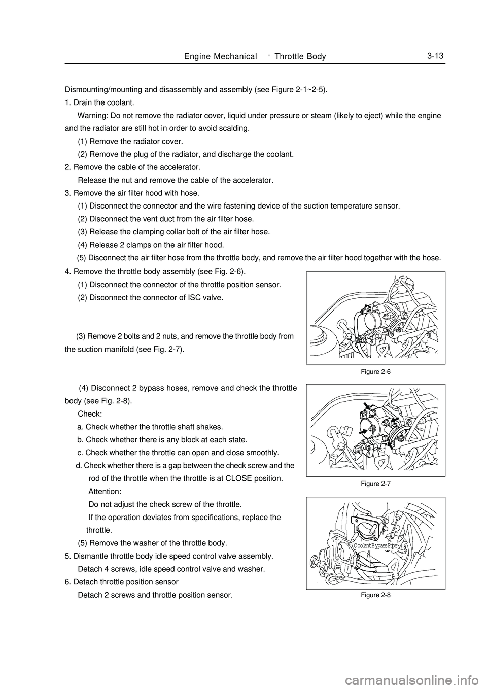
Figure 2-8Engine MechanicalThrottle Body3-134. Remove the throttle body assembly (see Fig. 2-6).
(1) Disconnect the connector of the throttle position sensor.
(2) Disconnect the connector of ISC valve.
(3) Remove 2 bolts and 2 nuts, and remove the throttle body from
the suction manifold (see Fig. 2-7).
(4) Disconnect 2 bypass hoses, remove and check the throttle
body (see Fig. 2-8).
Check:
a. Check whether the throttle shaft shakes.
b. Check whether there is any block at each state.
c. Check whether the throttle can open and close smoothly.
d. Check whether there is a gap between the check screw and the
rod of the throttle when the throttle is at CLOSE position.
Attention:
Do not adjust the check screw of the throttle.
If the operation deviates from specifications, replace the
throttle.
(5) Remove the washer of the throttle body.
5. Dismantle throttle body idle speed control valve assembly.
Detach 4 screws, idle speed control valve and washer.
6. Detach throttle position sensor
Detach 2 screws and throttle position sensor.Coolant Bypass Pipe -
Page 65 of 416

Section 2 Radiator Replacement1. Replace the radiator.
(1) Open the radiator cover.
(2) Open the water drain valve and discharge the coolant.
(3) Disconnect the water inlet pipe of the radiator.
(4) Disconnect the water outlet pipe of the radiator.
(5) Disconnect the input pipe of the oil cooler of the automatic transmission (automatic transmission).
(6) Disconnect the output pipe of the oil cooler of the automatic transmission (automatic transmission).
(7) Remove 4 bolts of the radiator mounting support (see Figure 5-8).Figure 5-8
Figure 5-9Cooling SystemRadiator Replacement3-24 (8)Remove the radiator assembly, remove 4 bolts, and separate
the fan and the fan housing (see Figure 5-9).
(9) Mount the cooling fan assembly.
a. Secure the compensating tank assembly on the cooling fan support with bolts; torque: 16 N.m.
b. Mount the fan and the fan housing with 3 bolts; torque: 7.5N.m.
c. Mount the cooling fan assembly on the radiator assembly with 3 bolts; torque: 16N.m.
d. Connect the overflow pipe on the compensating tank assembly and the radiator assembly, and fasten
with the elastic ring.
e. Mount the radiator assembly in the reverse order of dismounting. -
Page 71 of 416

The valve body fails.
12. The vehicle shifts before or after some gear points in the running status.
The vehicle switch or parking switch fails.
13. The vehicle has poor acceleration in running.
(1)The clutch or brake fails.
(2)The engine system fails.
14. The vehicle vibrates when it runs at a constant speed or accelerating speed.
(1)The hydraulic torque clutch pressure or hydraulic torque meter fails.
(2)The engine system or valve fails.
15. The acceleration switch system fails.
(1)The acceleration switch or ignition switch fails.
(2)The connector or automatic transmission control unit fails.I. Automatic transmissions Removal1. Put the select lever in "N" position
2. Remove 3 bolts of the flexibility plate (engine side)
3. Remove starter and 2 cooling hoses.
4. Disconnect neutral switch connector and odometer sensor.
5. Loosen the drain screw under the housing to bleed ATF and tighten the drain screw with sealing glue when
assembling. Tightening torque is 29~35N.m
6. Loosen the locking bolt for select lever cable.
7. Remove Drive Shaft LH&RH, using plastic stopper in the oil sealing of differential.
8. Detach suspension bolts.
9. Separate transmission from engine after bolts between engine and transmission remove.II. Automatic Transmission Installation1. Check whether torque converter of the transmission is in the right position, the methods as follows:
Check whether the distance from 3 anchor point of torque converter to front contact face of the transmission
box A 28mm , If the space A<28 mm, try install again. The way to install is that left hand catch hold of the
central anchor column of the converter and make it in alignment with input shaft as near as possible, push the torque
converter in rotating way by right hand until it gets to the bottom to meet the requirement of A 28 mm. (See
figure 7-1 and 2)
2. Install Flexibility plate and central plate on the crankshaft end face with 6 bolts in the direction of Figure 2.
Tightening torque is 45~55 N.m. Turn the longer hole of the Flexibility plate to the lowest of the engine position
in order to connect torque converter.Section 2 Hydraulic Torque Converter and TransaxleAutomatic Transaxle Assembly Hydraulic Torque Converter and Transaxle3-30 -
Page 98 of 416

Overhaul1. Drain manual transmission oil (M/T transmission)
Torque: 39N.m
2. Drain automatic transmission oil (A/T transmission)
Torque: 25N.m
3. Remove front wheel
4. Remove engine bottom left shield (M/T transaxle)
5. Remove engine bottom right shield (M/T transaxle)
6. Remove engine bottom shield assembly (A/T transaxle)
7. Remove front wheel hub left bolt
(1) Using a hammer and a drive shaft nut chisel, unstake the
staked part of the left wheel hub nut.
(2) While applying the brake pedal, remove the left wheel hub
nut.
Notice: the staked part of the nut should be fully unstaked,
otherwise it may damage the thread of the drive shaft.
8. Remove left front vehicle speed sensor (with ABS)
(1) Remove the bolt and clip, remove vehicle speed sensor and
brake hose from left front shock absorber assembly.
(2) Remove the bolt, separate the left front vehicle speed sensor
from steering knuckle.
9. Remove front stabilizer bar
(1) Use a 10mm wrench to hold the bolt, remove the nut
(2) Remove two collars, No.1 and No.2 gaskets, remove front
stabilizer barPropeller Shaft/DriveshaftFront Driveshaft4-21 -
Page 154 of 416

Power Steering System-Power Steering Gear4-77Replacement1. Drain the power steering system fluid
2. Loosen the high pressure pipes.
Loosen the high pressure pipes with special tool
3. Loosen the low pressure pipes
Loosen the low pressure pipes with special tool
4. Separate the tie rod from the steering knuckle
(1) Remove the cotter pin, loosen the groove type lock nut
(2) Separate the tie rod ball stud joint from the steering knuckle
taper hole5. Loosen the thread screw of the high and low pressure pipe on the steering gear assembly
6. Remove the boot and press plate
7. Disconnect the power steering gear assembly from the steering column
Remove the steering gear pinion shaft spline lock bolt on the universal joint yoke
8. Remove power steering gear assembly
Remove 2 steering gear assembly set bolts. Remove the power steering gear assembly
9. Installation is in the reverse order of the removal
Notice:
(1) Insert the steering gear pinion shaft spline into the spline hole of the universal joint yoke, make sure that
the positions of the notch of the steering gear pinion shaft and the lock bolt of the universal joint yoke are
correct
(2) Secure the power steering gear with 2 bolts, torque: 125~152N.m
(3) Tighten the steering gear pinion shaft spline lock bolt on the universal joint yoke, torque: 22~34N.m
(4) Install the boot and press plate
(5) Install the threaded connector of the power steering high and low pressure pipe to the power steering gear,
torque: 25~32N.m
Page 275 of 416

Overhaul1. Drain the coolant (refer to Coolant for details).
2. Disconnect A/C pipeline assembly.
(1) Remove the bolt, disconnect A/C pipeline assembly
(2) Remove 2 O-rings form the A/C pipeline assembly.
Notice: O-ring is a non-reusable part.
3. Disconnect the water pipe assembly connecting the heater core.
Loosen the dual steel wire circlip, disconnect the water pipe
connecting the heater core.
4. Remove console assembly
Refer to Interior Trim: Removal of the Console Assembly
5. Remove central cross member assembly
(1) Unscrew the wire harness clip and screw.
(2) Remove the nut and bolt.
(3) Remove cross member assembly.
6. Remove A/C lower left and right air outlet pipe
(1) Unscrew the two clips, disconnect the A/C lower left air outlet
pipe.
(2) Unscrew the two clips, disconnect the A/C lower right air
outlet pipe.5-88clip clipclip
screw,nut and
boltAir Conditioning System ¡ª¡ªHeater, Ventilation and Air Conditioning
Page 281 of 416

Section 7 Compressor AssemblyComponent ViewReplacement1. System drains coolant (refer to Coolant for details)
2. Remove multi-wedge belt (refer to Multi-wedge Belt (A/C Compressor to Crankshaft Pulley for details)).Multi-Wedge Belt 4PK820Tensioner Assembly
Compressor Support
Hexagonal Bolt Spring and
Plate Washer Set (3 Pcs)Hexagonal Bolt
Spring and Plate
Washer Set
Compressor
Assembly
Hexagonal Bolt M8 x105Air Conditioning System -Compressor Assembly5-943. Disconnect the suction vent
(1) Remove the bolt, disconnect the suction vent.
(2) Remove the O-ring from the suction vent.
4. Disconnect the exhaust vent
(1) Remove the bolt, disconnect the exhaust vent.
(2) Remove the O-ring from the exhaust vent.
Notice:
Use vinyl tape seal all the interfaces of the disconnected
parts to avoid entry of water and foreign objects.
O ring is a non-reusable part.Suction port Discharge
port
Page 284 of 416

Overhaul1. Drain coolant (refer to Coolant for details).
2. Remove condenser fan motor assembly
(1) Disconnect condenser fan motor wire harness connector.
(2) Unscrew 1 bolt, remove condenser fan motor assembly.
3. Disconnect the liquid tube
(1) Remove the bolt, disconnect the liquid tube from the condenser.
(2) Remove the Oring from the liquid tube.
4. Disconnect the high and low pressure pipe assembly
(1) Remove the bolt, disconnect the high and low pressure tube
assembly from the condenser.
(2) Remove the Oring from the high and low pressure tube
assembly.
Notice: Use vinyl tape seal all the interfaces of the disconnected
parts to avoid entry of water and foreign objects.
5. Remove engine hood lock assembly
(1) remove the bolt, remove engine hood lock assemblyAir Conditioning System -Condenser Fan Motor and Condenser Assembly5-97