2008 GEELY MK engine oil
[x] Cancel search: engine oilPage 47 of 416

Figure 1-7Figure 1-6
Figure 1-8Engine AssemblyRemoval of the Engine Assembly from the Vehicle3-69. Remove the oil tank assembly of the power steering pump (with power steering).
10. Remove the radiator assembly.
11. Disconnect the harness.
12. Disengage the steering column assembly.
13. Disengage No.2 steering countershaft assembly (see Figure 1-6).
Remove the cover sheet of the steering column on the car body.
14. Remove the exhaust pipe assembly in the front.
15. Remove the nut on the front hub (Parts on the other side are
disassembled in the same way).
16. Disconnect the speed sensor on the front wheel (with ABS).
17. Disengage the ball assembly of the steering tie rod.
18. Disengage the front suspension arm sub-assembly.
19. Disengage the front drive shaft assembly (see Figure 1-7).
20. Disengage the front drive shaft from the hub with a plastic
hammer.
21. Disconnect the shift cable or the tie-rod assembly of the
transmission.
22. Disconnect the clutch wheel cylinder assembly or the clutch
cable (M/T).
23. Remove the engine assembly together with the drive bridge:
(1) Hoist the engine a bit with lifting equipment;
(2) Remove 2 bolts, and disengage the right support of the engine
(see Figure 1-8);
(3) Remove 2 bolts, and disengage the left support of the engine;
(4) Remove one bolt, 3 nuts and disengage the rear support of the
engine;
(5) Remove the engine together with the drive bridge and place
them on the floor;
(6) Lift the body.Mark -
Page 49 of 416

Chapter 2 Engine MechanicalSection 1 Engine ComponentsComponent ViewFigure 2-1Engine MechanicalEngine Components3-8Upside of radiator support
Engine cover lock assembly
Starter assembly
Output pipe of oil cooler
Input pipe of oil coolerTransmission control cable assembly Fuel oil sub-assembly Accelerator control cable assemble
Water inlet pipe of heater
Water outlet pipe of heaterTransmission control cable assemblySuitable for 1.5L/1.6L(Tight coupling)Suitable for 1.3L/1.5L(Non-tight coupling) Radiator assemblyAir filter assembly with hose
Clutch release assembly
Water inlet pipe of radiator
Water outlet pipe of radiator
Battery -
Page 51 of 416

Component ViewFigure 2-3Engine MechanicalEngine Components3-10adjusting support
with power steering
Vane pump assembly with
power steering
Pump support with
power steeringHex. flange
bolt M6¡Á50
Ignition coil
Ignition coilinstallation bracket
Bolt M8¡Á31Fuel oil pipe subassembly
Fuel oil pipe clip
Vent ductSecondary wireBypass hose
Rear end housingWater outlet
pipe housing
No.1 heat shield of
exhaust manifoldOil filter assembly
Washer
Exhaust manifold
Support of exhaust
manifoldO-ring
Fastener of
No.1
injectorInjector
O-ring
Throttle assemblySuction manifold Washer
WasherKnock sensor
Water temperature sensorCrankshaft position sensorGenerator assemblyNo.1 support of compressor
Air conditioner compressorWater inlet pipe housing -
Page 56 of 416

Chapter 3 Fuel SystemSection 1 Check Fuel System PressureOn-board inspection
1. Check the operation of the fuel pump.
(1) Connect the positive and the negative of the battery to
appropriate connector sockets of the fuel pump (see Figure 3-1).
Attention: Do not start the engine.
If there is pressure present, you will hear that the fuel is flowing.
If there is no pressure present, check the fusible cutout, fuse, EFI
open-circuit relay, fuel pump, ECM (Electronic Control Module) and
circuit joint.
(2) Turn the ignition switch to "OFF".
2. Check the pressure of the fuel.
(1) Check whether the battery voltage is more than 12V.
(2) Disconnect the negative wiring cable from the battery.
(3) Mount a pressure gauge on the fuel input pipe
(see Figure 3-2).
(4) Connect the negative terminal of the battery.
(5) Measure the fuel pressure.
Fuel oil pressure: 265-304kPa
If the pressure is low, check the fuel pipe and connection,
fuel pump, and fuel filter. If the pressure is too high,
replace the regulator.
(6) Start the engine. Measure the fuel pressure at idle speed. The
fuel pressure is 265-304KPa. If the pressure is unsatisfactory, checkFigure 3-1
Figure 3-3 Figure 3-2Fuel SystemCheck Fuel System Pressure3-15the fuel pump, pressure regulator, and injector, and replace if necessary.
(7) After shutting down the engine, check the fuel pressure and
keep the specified pressure for about 5 minutes. The fuel pressure is:
147KPa.
3. The fuel oil pressure regulator (DR) (see Figure 3-3).
Mounting position: On the distributing pipe for fuel.
Faults: Too low or too high fuel pressure, or hard to start.
General causes: Using poor fuel for a long time results in: 1.
strainer blocked; 2. serious leakage caused by particles and impurities.
Other reasons: Man-made mechanical damage, etc.
Maintenance precautions: During maintenance: 1. Never impact the diaphragm element with high pressure
gas; 2. Never clean it with aggressively corrosive liquid; 3. No distortion caused by external force.
Easy measuring method: For the system with oil return, connect a pressure gauge for the fuel on the suction
pipe, start the engine, and run at idle speed. Now, the fuel pressure in the engine should be about 260KPa; pull out
the vacuum pipe of the fuel pressure regulator, and the pressure should be 300KPa approximately.Battery
T conector
Hose
Hose
Fuel Inlet Pipe
Fuel Pipe
Conector -
Page 63 of 416

2. Check the engine coolant quantity in the compensating tank.
The coolant level should be between LOW and FULL.
3. Check the coolant quality.
(1) Remove the radiator cover.
Do not remove the radiator cover when the engine and the radiator are still hot in order to avoid scalding
since the liquid vapor may inject.
(2) Check whether there are excessive deposit and rust or sundries around the radiator cover. The coolant is
not allowed to contact with oil.
(3) Remount the radiator cover.Chapter 5 Cooling SystemSection 1 System Inspection1. Check leakage in the cooling system (see Figure 5-1).
(1) Fill coolant in the radiator, and mount the tester at the radiator
cover port.
(2) Start the engine.
(3) Keep the pump pressure at 118KPa without drop. If the
pressure drops,check whether there is any leakage at the port,
radiator and water pump; if not, check the heating core,
cylinder and cap.Figure 5-1
Figure 5-2
Figure 5-3 Figure 5-4 (4) When the thermostat is at low temperature (lower than 77°C), the valve should close completely.Cooling SystemSystem Inspection3-224. Thermostat
Notes:
The temperature indicated on the thermostat is marked as open
temperature of the valve (see Figure 5-2).
(1) Submerge the thermostat into water and heat gradually.
(2) Check the open temperature of the valve.
Open temperature of the valve: 80-84°C
(3) Check the lift of the valve (see Figure 5-3 and Figure 5-4).
Lift of the valve: 8mm or more at 95°CTester of radiator cap
8.0mm or more -
Page 67 of 416

Table 6-1 Frequent problem diagnosisPossible causes
Transmission or the engine is suspended loosely or damaged;
Axial gap is improper;
Gear or bearing is worn or damaged;
Unsatisfactory transmission oil is used or oil level is low;
Engine idle is incorrect.
The oil seal or the O-ring is damaged.
The control cable is unqualified;
Synchronizer is poorly contacted with gear or worn;
Elasticity of the synchronous spring is insufficient;
Unqualified transmission oil is used.
Fork of the shift gear is worn or lifting spring is broken;
Gap between the synchronizer bush and the sleeve spline is too large;
Gear or bearing is worn or damaged. Sympton
Vibration and noise
Oil leakage of the transmission
Hard to shift
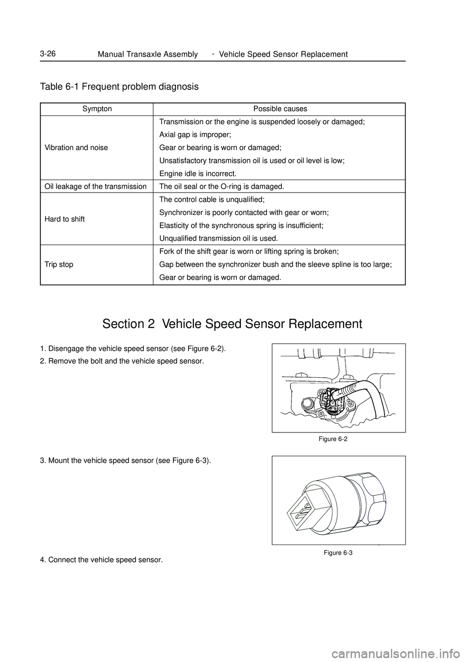
Trip stopManual Transaxle Assembly Vehicle Speed Sensor Replacement3-261. Disengage the vehicle speed sensor (see Figure 6-2).
2. Remove the bolt and the vehicle speed sensor.
3. Mount the vehicle speed sensor (see Figure 6-3).
4. Connect the vehicle speed sensor.Section 2 Vehicle Speed Sensor ReplacementFigure 6-2
Figure 6-3 -
Page 68 of 416

Figure 6-5Manual Transaxle Assembly Manual Transaxle Replacement3-27Section 3 Manual Transaxle ReplacementReplace1. Open the engine cover.
2. Remove the battery.
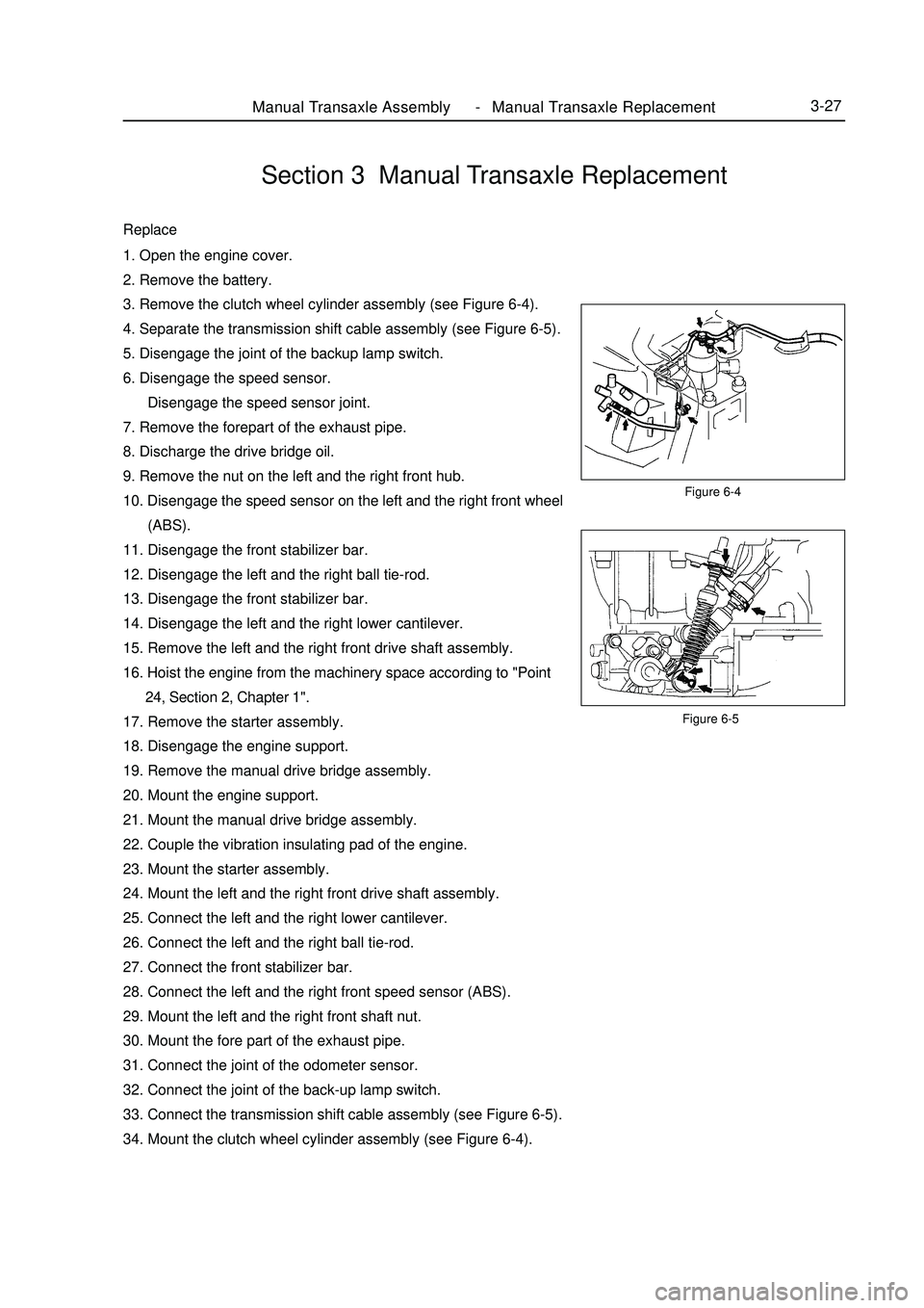
3. Remove the clutch wheel cylinder assembly (see Figure 6-4).
4. Separate the transmission shift cable assembly (see Figure 6-5).
5. Disengage the joint of the backup lamp switch.
6. Disengage the speed sensor.
Disengage the speed sensor joint.
7. Remove the forepart of the exhaust pipe.
8. Discharge the drive bridge oil.
9. Remove the nut on the left and the right front hub.
10. Disengage the speed sensor on the left and the right front wheel
(ABS).
11. Disengage the front stabilizer bar.
12. Disengage the left and the right ball tie-rod.
13. Disengage the front stabilizer bar.
14. Disengage the left and the right lower cantilever.
15. Remove the left and the right front drive shaft assembly.
16. Hoist the engine from the machinery space according to "Point
24, Section 2, Chapter 1".
17. Remove the starter assembly.
18. Disengage the engine support.
19. Remove the manual drive bridge assembly.
20. Mount the engine support.
21. Mount the manual drive bridge assembly.
22. Couple the vibration insulating pad of the engine.
23. Mount the starter assembly.
24. Mount the left and the right front drive shaft assembly.
25. Connect the left and the right lower cantilever.
26. Connect the left and the right ball tie-rod.
27. Connect the front stabilizer bar.
28. Connect the left and the right front speed sensor (ABS).
29. Mount the left and the right front shaft nut.
30. Mount the fore part of the exhaust pipe.
31. Connect the joint of the odometer sensor.
32. Connect the joint of the back-up lamp switch.
33. Connect the transmission shift cable assembly (see Figure 6-5).
34. Mount the clutch wheel cylinder assembly (see Figure 6-4).Figure 6-4 -
Page 70 of 416

Chapter 7 Automatic Transaxle AssemblySection 1 Frequent Problems DiagnosisPossible Cause1. There is no scan information.
(1)The diagnosis system fails.
(2)The automatic transmission unit fails.
2. The engine can't start.
(1)The engine system fails.
(2)The fuel pump or torque meter fails.
3. The vehicle cant' runs forwards.
(1)The circuit voltage is improper.
(2)The rear clutch or single clutch fails.
(3)The valve fails.
4. The vehicle can't run backwards.
(1)The low speed brake or front clutch pressure is improper.
(2)The front clutch or low speed reverse gear fails.
(3)The valve fails.
5. The vehicle can't runs forwards or backwards.
(1)The pressure deduction is improper or the transmission signal fails.
(2)There is pressure in the oil pump or the valve body fails.
6. The engine stalls in gear shift.
(1)The engine system or clutch torque meter fails.
(2)The valve body or torque meter fails.
7. The vehicle vibrates and lasts for a long time when the gear is shifted from N to D.
(1)The rear clutch fails.
(2)The valve body clutch fails.
(3)The restrictor switch fails.
8. The vehicle vibrates and lasts for a long time when the gear is shifted from N to R.
(1)The front clutch pressure fails.
(2)The front clutch or valve body fails.
(3)The low speed reserve gear pressure or low speed reverse gear fails.
9. The vehicle vibrates and lasts for a long time when the gear is shifted from N to D/R.
(1)The pressure reduction fails.
(2)The oil pump fails.
(3)The valve body fails.
10. The gear shift impacts.
(1)The servo switch or restrictor position switch fails.
(2)The pressure is decreases abnormally.
(3)The clutch or brake fails.
11. All gear shift points are either too early or too late in the running status.Automatic Transaxle Assembly Frequent Problems Diagnosis3-29 -