2008 GEELY MK check engine
[x] Cancel search: check enginePage 48 of 416

Section 3 Drive Belt Replacement1. Remove the V-belt of the generator (see Figure 1-9).
(1) Release bolts A and B.
(2) Release the bolt C and remove the V-belt.
2. Remove the V-belt (from the air conditioner compressor to the
crankshaft sheave (see Figure 1-10).
(1) Release the nut A.
(2) Release the bolt B, and remove the V-belt.
3. Remove the belt of the water pump.
Release bolts A and B, and remove V-belt.
4. Mount the V-belt of the water pump.
Mount the V-belt on the sheave briefly.
5. Adjust the V-belt of the steering pump (see Figure 1-11).
(1) Adjust the tension of the power steering belt, and fasten the
bolt B.
(2) Fasten the bolt A.
Torque: 39N.mFigure 1-9
Figure 1-10
Figure 1-11Engine AssemblyDrive Belt Replacement3-76. Mount No.1 V-belt (from the air conditioner compressor to the crankshaft sheave). (See Figure 1-10).
7. Adjust No.1 V-belt (from the air conditioner compressor to the crankshaft sheave).
(1) Adjust the tension of the belt of the air conditioner by fastening the bolt B.
(2) Fasten the nut A. Torque: 39N.m.
8. Mount the V-belt of the generator (see Figure 1-9).
9. Adjust the V-belt of the generator.
Fasten the bolt A, and then the bolt B.
Torque: 18N.m for bolt A, 58N.m for bolt B.
10. Check distortion and tension of the driving belt. -
Page 54 of 416

Dismounting/mounting and disassembly and assembly (see Figure 2-1~2-5).
1. Drain the coolant.
Warning: Do not remove the radiator cover, liquid under pressure or steam (likely to eject) while the engine
and the radiator are still hot in order to avoid scalding.
(1) Remove the radiator cover.
(2) Remove the plug of the radiator, and discharge the coolant.
2. Remove the cable of the accelerator.
Release the nut and remove the cable of the accelerator.
3. Remove the air filter hood with hose.
(1) Disconnect the connector and the wire fastening device of the suction temperature sensor.
(2) Disconnect the vent duct from the air filter hose.
(3) Release the clamping collar bolt of the air filter hose.
(4) Release 2 clamps on the air filter hood.
(5) Disconnect the air filter hose from the throttle body, and remove the air filter hood together with the hose.Figure 2-6
Figure 2-7
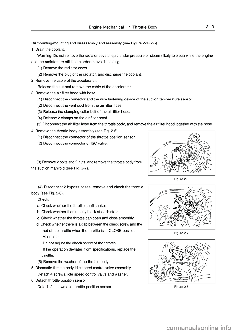
Figure 2-8Engine MechanicalThrottle Body3-134. Remove the throttle body assembly (see Fig. 2-6).
(1) Disconnect the connector of the throttle position sensor.
(2) Disconnect the connector of ISC valve.
(3) Remove 2 bolts and 2 nuts, and remove the throttle body from
the suction manifold (see Fig. 2-7).
(4) Disconnect 2 bypass hoses, remove and check the throttle
body (see Fig. 2-8).
Check:
a. Check whether the throttle shaft shakes.
b. Check whether there is any block at each state.
c. Check whether the throttle can open and close smoothly.
d. Check whether there is a gap between the check screw and the
rod of the throttle when the throttle is at CLOSE position.
Attention:
Do not adjust the check screw of the throttle.
If the operation deviates from specifications, replace the
throttle.
(5) Remove the washer of the throttle body.
5. Dismantle throttle body idle speed control valve assembly.
Detach 4 screws, idle speed control valve and washer.
6. Detach throttle position sensor
Detach 2 screws and throttle position sensor.Coolant Bypass Pipe -
Page 55 of 416

Section 3 Valve Clearance AdjustmentAdjust the throttle gap (see Figure 2-9).
Calculate the thickness of new washer to allow the
gap of the exhaust valve to reach a specified value.
N=T+(A-0.2mm)
Note: where,
N -- Thickness of new washer
T -- Thickness of the washer removed
A -- Measured throttle gap
Calculation formula of the suction valve is: N= T+(A-0.3mm).
(1) Remove the adjusting washer.
a. Rotate the crankshaft until the top of the cam is upwards.
b. The nick of the valve tappet faces toward the front.
c. Press the valve tappet down with a special tool, and place
the tool between the camshaft and the valve tappet (see
Figure 2-10).
Tip:
Place one end, with a mark "9", of the special tool to the position
shown in Figure 1-24 a bit aslant.
If the special tool (B) is put into a deep position too much, it will
be clipped by the washer. In order to avoid the special tool (B) being
too hard to take out, put it into slowly by decreasing the inclination
angle from the suction side.
It is difficult for the special tool (B) to insert due to the shape
of the cam when inserting it from the suction side to the back side of
No.3 cylinder (see Figure 2-10). When adjusting the washer, therefore,
it is advisable to insert from the exhaust side.
d. Press the valve tappet down alternately with the special tool
(A) and (B) to check the throttle gap.
(2) Re-mount the adjusting washer.
a. Mount a new adjusting washer on the valve tappet.
b. Press the valve tappet down with the special tool (A), and
remove the special tool (B).
c. Re-check the throttle gap.Figure 2-9
Figure 2-10
Figure 2-11Engine MachineryValve Clearance Adjustment3-14Camshaft TopUp
Vehicle Front
NotchNotchNotchNo.3 Cylinder back side -
Page 56 of 416

Chapter 3 Fuel SystemSection 1 Check Fuel System PressureOn-board inspection
1. Check the operation of the fuel pump.
(1) Connect the positive and the negative of the battery to
appropriate connector sockets of the fuel pump (see Figure 3-1).
Attention: Do not start the engine.
If there is pressure present, you will hear that the fuel is flowing.
If there is no pressure present, check the fusible cutout, fuse, EFI
open-circuit relay, fuel pump, ECM (Electronic Control Module) and
circuit joint.
(2) Turn the ignition switch to "OFF".
2. Check the pressure of the fuel.
(1) Check whether the battery voltage is more than 12V.
(2) Disconnect the negative wiring cable from the battery.
(3) Mount a pressure gauge on the fuel input pipe
(see Figure 3-2).
(4) Connect the negative terminal of the battery.
(5) Measure the fuel pressure.
Fuel oil pressure: 265-304kPa
If the pressure is low, check the fuel pipe and connection,
fuel pump, and fuel filter. If the pressure is too high,
replace the regulator.
(6) Start the engine. Measure the fuel pressure at idle speed. The
fuel pressure is 265-304KPa. If the pressure is unsatisfactory, checkFigure 3-1
Figure 3-3 Figure 3-2Fuel SystemCheck Fuel System Pressure3-15the fuel pump, pressure regulator, and injector, and replace if necessary.
(7) After shutting down the engine, check the fuel pressure and
keep the specified pressure for about 5 minutes. The fuel pressure is:
147KPa.
3. The fuel oil pressure regulator (DR) (see Figure 3-3).
Mounting position: On the distributing pipe for fuel.
Faults: Too low or too high fuel pressure, or hard to start.
General causes: Using poor fuel for a long time results in: 1.
strainer blocked; 2. serious leakage caused by particles and impurities.
Other reasons: Man-made mechanical damage, etc.
Maintenance precautions: During maintenance: 1. Never impact the diaphragm element with high pressure
gas; 2. Never clean it with aggressively corrosive liquid; 3. No distortion caused by external force.
Easy measuring method: For the system with oil return, connect a pressure gauge for the fuel on the suction
pipe, start the engine, and run at idle speed. Now, the fuel pressure in the engine should be about 260KPa; pull out
the vacuum pipe of the fuel pressure regulator, and the pressure should be 300KPa approximately.Battery
T conector
Hose
Hose
Fuel Inlet Pipe
Fuel Pipe
Conector -
Page 59 of 416

Section 4 Fuel Emission Control SystemOn-board Inspection1. Check the operation when disconnecting the fuel supply.
(1) Warm the engine up to 2,500r/min at least, and check the noise of the injector with a sound level meter
(see Figure 3-9).
(2) When the throttle releases, the noise from the injector should stop immediately; repeat several times.
2. Check the fuel vapor discharge control system (see Figure 3-10).
(1) After starting the engine, disconnect the vacuum pipe.
(2) Make sure that there is vacuum present at the canister control valve (TEV) port when selecting ”ACTIVE
TEST" and "PURGE TEV" based on the display on the fault diagnosis instrument.
(3) After "ACTIVE TEST", connect the vacuum pipe.
(4) Carry out "ECM DATA MONITOR" on the fault diagnosis instrument, and then select "PURGE TEV"
for operation inspection.
(5) Start up the car after the engine warms up, and make sure the TEV ON from OFF (see Figure 3-11).
3. Check whether there is any distortion or damage on the filling cap and the washer (see Figure 3-12).Figure 3-9 Figure 3-10Fuel SystemFuel Emission Control System3-18Figure 3-11 Figure 3-12Sound level meter
Gasket -
Page 63 of 416

2. Check the engine coolant quantity in the compensating tank.
The coolant level should be between LOW and FULL.
3. Check the coolant quality.
(1) Remove the radiator cover.
Do not remove the radiator cover when the engine and the radiator are still hot in order to avoid scalding
since the liquid vapor may inject.
(2) Check whether there are excessive deposit and rust or sundries around the radiator cover. The coolant is
not allowed to contact with oil.
(3) Remount the radiator cover.Chapter 5 Cooling SystemSection 1 System Inspection1. Check leakage in the cooling system (see Figure 5-1).
(1) Fill coolant in the radiator, and mount the tester at the radiator
cover port.
(2) Start the engine.
(3) Keep the pump pressure at 118KPa without drop. If the
pressure drops,check whether there is any leakage at the port,
radiator and water pump; if not, check the heating core,
cylinder and cap.Figure 5-1
Figure 5-2
Figure 5-3 Figure 5-4 (4) When the thermostat is at low temperature (lower than 77°C), the valve should close completely.Cooling SystemSystem Inspection3-224. Thermostat
Notes:
The temperature indicated on the thermostat is marked as open
temperature of the valve (see Figure 5-2).
(1) Submerge the thermostat into water and heat gradually.
(2) Check the open temperature of the valve.
Open temperature of the valve: 80-84°C
(3) Check the lift of the valve (see Figure 5-3 and Figure 5-4).
Lift of the valve: 8mm or more at 95°CTester of radiator cap
8.0mm or more -
Page 64 of 416

Figure 5-6
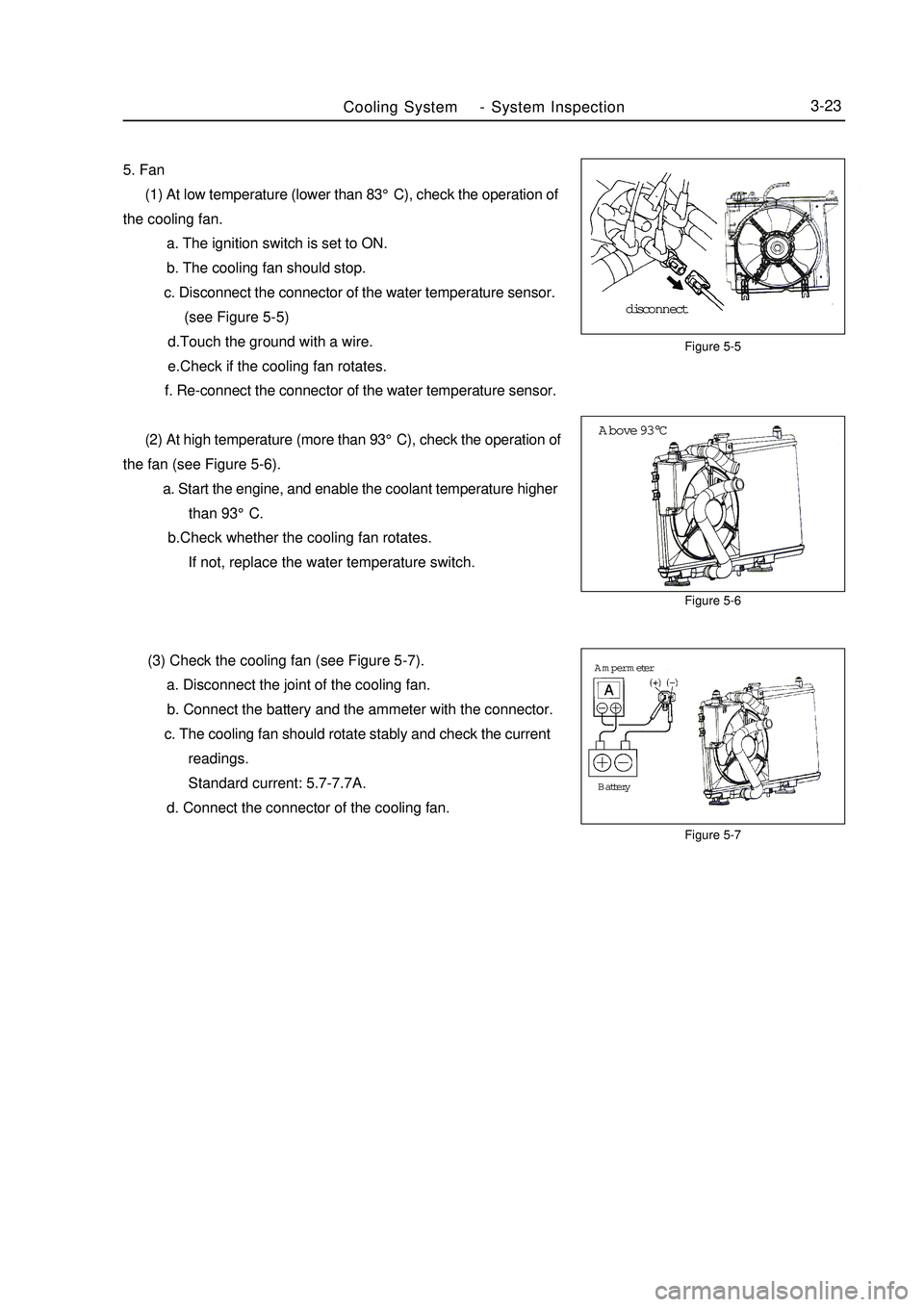
Figure 5-7Above 93°CFigure 5-5Cooling SystemSystem Inspection3-235. Fan
(1) At low temperature (lower than 83°C), check the operation of
the cooling fan.
a. The ignition switch is set to ON.
b. The cooling fan should stop.
c. Disconnect the connector of the water temperature sensor.
(see Figure 5-5)
d.Touch the ground with a wire.
e.Check if the cooling fan rotates.
f. Re-connect the connector of the water temperature sensor.
(2) At high temperature (more than 93°C), check the operation of
the fan (see Figure 5-6).
a. Start the engine, and enable the coolant temperature higher
than 93°C.
b.Check whether the cooling fan rotates.
If not, replace the water temperature switch.
(3) Check the cooling fan (see Figure 5-7).
a. Disconnect the joint of the cooling fan.
b. Connect the battery and the ammeter with the connector.
c. The cooling fan should rotate stably and check the current
readings.
Standard current: 5.7-7.7A.
d. Connect the connector of the cooling fan.disconnectBattery Amper meter -
Page 71 of 416

The valve body fails.
12. The vehicle shifts before or after some gear points in the running status.
The vehicle switch or parking switch fails.
13. The vehicle has poor acceleration in running.
(1)The clutch or brake fails.
(2)The engine system fails.
14. The vehicle vibrates when it runs at a constant speed or accelerating speed.
(1)The hydraulic torque clutch pressure or hydraulic torque meter fails.
(2)The engine system or valve fails.
15. The acceleration switch system fails.
(1)The acceleration switch or ignition switch fails.
(2)The connector or automatic transmission control unit fails.I. Automatic transmissions Removal1. Put the select lever in "N" position
2. Remove 3 bolts of the flexibility plate (engine side)
3. Remove starter and 2 cooling hoses.
4. Disconnect neutral switch connector and odometer sensor.
5. Loosen the drain screw under the housing to bleed ATF and tighten the drain screw with sealing glue when
assembling. Tightening torque is 29~35N.m
6. Loosen the locking bolt for select lever cable.
7. Remove Drive Shaft LH&RH, using plastic stopper in the oil sealing of differential.
8. Detach suspension bolts.
9. Separate transmission from engine after bolts between engine and transmission remove.II. Automatic Transmission Installation1. Check whether torque converter of the transmission is in the right position, the methods as follows:
Check whether the distance from 3 anchor point of torque converter to front contact face of the transmission
box A 28mm , If the space A<28 mm, try install again. The way to install is that left hand catch hold of the
central anchor column of the converter and make it in alignment with input shaft as near as possible, push the torque
converter in rotating way by right hand until it gets to the bottom to meet the requirement of A 28 mm. (See
figure 7-1 and 2)
2. Install Flexibility plate and central plate on the crankshaft end face with 6 bolts in the direction of Figure 2.
Tightening torque is 45~55 N.m. Turn the longer hole of the Flexibility plate to the lowest of the engine position
in order to connect torque converter.Section 2 Hydraulic Torque Converter and TransaxleAutomatic Transaxle Assembly Hydraulic Torque Converter and Transaxle3-30 -