Page 89 of 392
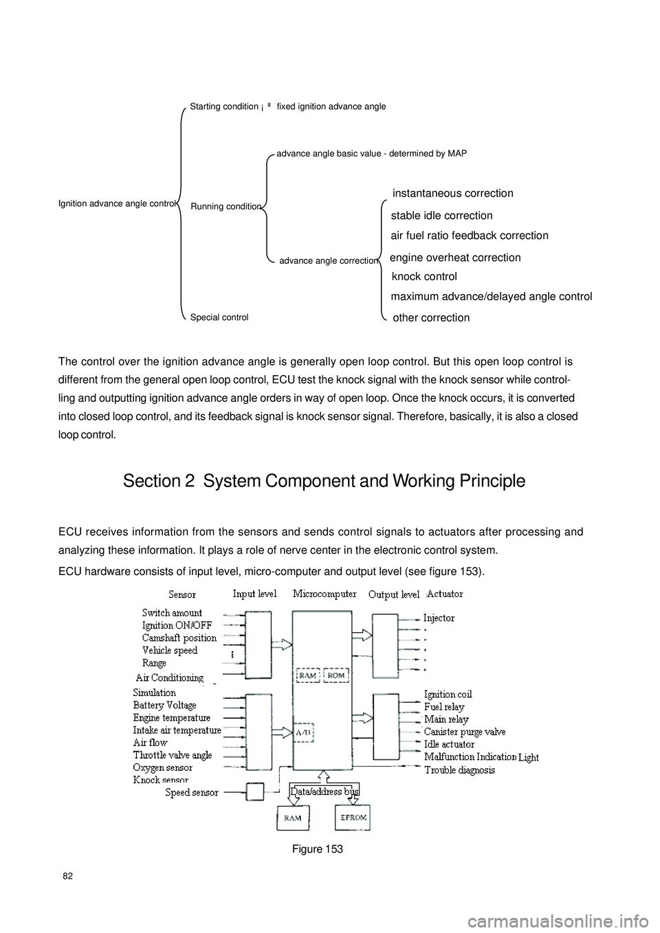
82The control over the ignition advance angle is generally open loop control. But this open loop control is
different from the general open loop control, ECU test the knock signal with the knock sensor while control-
ling and outputting ignition advance angle orders in way of open loop. Once the knock occurs, it is converted
into closed loop control, and its feedback signal is knock sensor signal. Therefore, basically, it is also a closed
loop control.Section 2 System Component and Working PrincipleECU receives information from the sensors and sends control signals to actuators after processing and
analyzing these information. It plays a role of nerve center in the electronic control system.
ECU hardware consists of input level, micro-computer and output level (see figure 153).
Figure 153Ignition advance angle control Starting condition ¡ª fixed ignition advance angle
Running conditionSpecial controladvance angle basic value - determined by MAPadvance angle correctioninstantaneous correction
stable idle correction
air fuel ratio feedback correction
engine overheat correction
knock control
maximum advance/delayed angle controlother correction
Page 90 of 392
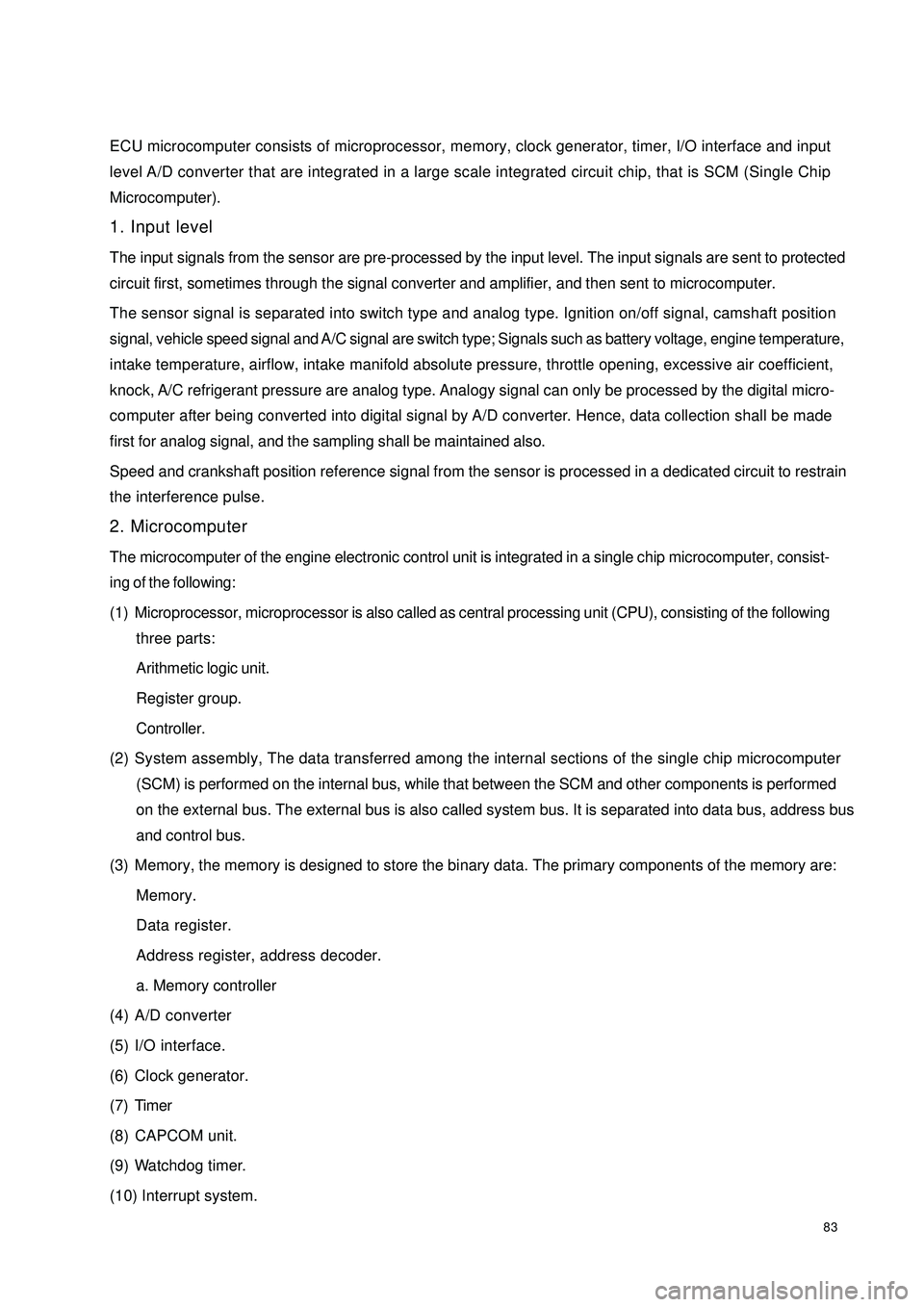
83ECU microcomputer consists of microprocessor, memory, clock generator, timer, I/O interface and input
level A/D converter that are integrated in a large scale integrated circuit chip, that is SCM (Single Chip
Microcomputer).
1. Input level
The input signals from the sensor are pre-processed by the input level. The input signals are sent to protected
circuit first, sometimes through the signal converter and amplifier, and then sent to microcomputer.
The sensor signal is separated into switch type and analog type. Ignition on/off signal, camshaft position
signal, vehicle speed signal and A/C signal are switch type; Signals such as battery voltage, engine temperature,
intake temperature, airflow, intake manifold absolute pressure, throttle opening, excessive air coefficient,
knock, A/C refrigerant pressure are analog type. Analogy signal can only be processed by the digital micro-
computer after being converted into digital signal by A/D converter. Hence, data collection shall be made
first for analog signal, and the sampling shall be maintained also.
Speed and crankshaft position reference signal from the sensor is processed in a dedicated circuit to restrain
the interference pulse.
2. Microcomputer
The microcomputer of the engine electronic control unit is integrated in a single chip microcomputer, consist-
ing of the following:
(1) Microprocessor, microprocessor is also called as central processing unit (CPU), consisting of the following
three parts:
Arithmetic logic unit.
Register group.
Controller.
(2) System assembly, The data transferred among the internal sections of the single chip microcomputer
(SCM) is performed on the internal bus, while that between the SCM and other components is performed
on the external bus. The external bus is also called system bus. It is separated into data bus, address bus
and control bus.
(3) Memory, the memory is designed to store the binary data. The primary components of the memory are:
Memory.
Data register.
Address register, address decoder.
a. Memory controller
(4) A/D converter
(5) I/O interface.
(6) Clock generator.
(7) Timer
(8) CAPCOM unit.
(9) Watchdog timer.
(10) Interrupt system.
Page 91 of 392
843. Output Level
ECU output level is designed to send control signal to the actuators of the electronic control system based on
the orders of the microprocessor in the micro-controller. The microprocessor control the output level by
controlling the occurrence position of the pulse, its length and duty ratio.
(1) Injection output level
The microprocessor controls the pulse length of the injection output level by making sure whether to
trigger to circuit or not in the injection output level.
(2) Ignition input level
The ignition output level is designed to amplify the ignition signal from the microprocessor into the primary
current of the ignition coil.
(3) Electric fuel pump output level
ECU microcontroller control the pump relay through electric fuel pump output level, and then control the
on and off of the electric fuel pump based on the current operating conditions.
(4) Other output levels
Control the output levels of the idle control valve, carbon canister solenoid valve, malfunction indicator
lamp. MR479Q, MR479QA, MR481QA engine idle control are closed loop control system, their injection
and ignition control are also closed loop control system.
Page 139 of 392
1327. Remove the combination switch assembly
(1) Remove 3 set screws.
(2) Disconnect headlamp dimmer switch and wiper and washer switch wire harness
(3) Remove the combination switch assembly
8. Disconnect the universal joint
Remove the locking bolt between the joint yoke and the power steering gear
9. Remove steering column assembly.
(1) Remove the wire harness connector on the steering column assembly
(2) Remove 2 bolts, 2 nuts and the steering column assembly
10. Remove ignition switch lock core assembly
(1) Remove the ignition switch wire harness
(2) Remove the screw, then remove the ignition switch assembly
Page 140 of 392
13311. Complete the service or replace the steering column assembly, the installation procedure is in the reverseorder of the removal
Notice:
(1) after the installation of the ignition lock core, check the steering lock operation: the
steering mechanism lock when the ignition key is pulled out; the steering mechanism
unlock when the key is inserted and turned to ACC position
(2)The torque of the 2 bolts and 2 nuts securing the steer column assembly:
16~26N.m
(3) connect the wire harness into place and make sure the wiring is good
(4) After properly adjust the positions of the combination switch and the steering column
upper and lower cover, tighten the 3 screws attaching the combination switch and the
steering column
(5) Torque of the universal joint yoke and steering gear assembly locking bolt: 22~34N.m
(6) Torque of the 4 set bolts of the dust cover and press plate: 16~26N.m
(7) When installing the steering wheel assembly, align the matchmarks of the steering wheel
and steering main shaft assembly,
Torque of the steering wheel specific inner torx bolt: 40~60N.m
(7) Check the air bag, it is not allowed to use the air bag parts from another vehicle
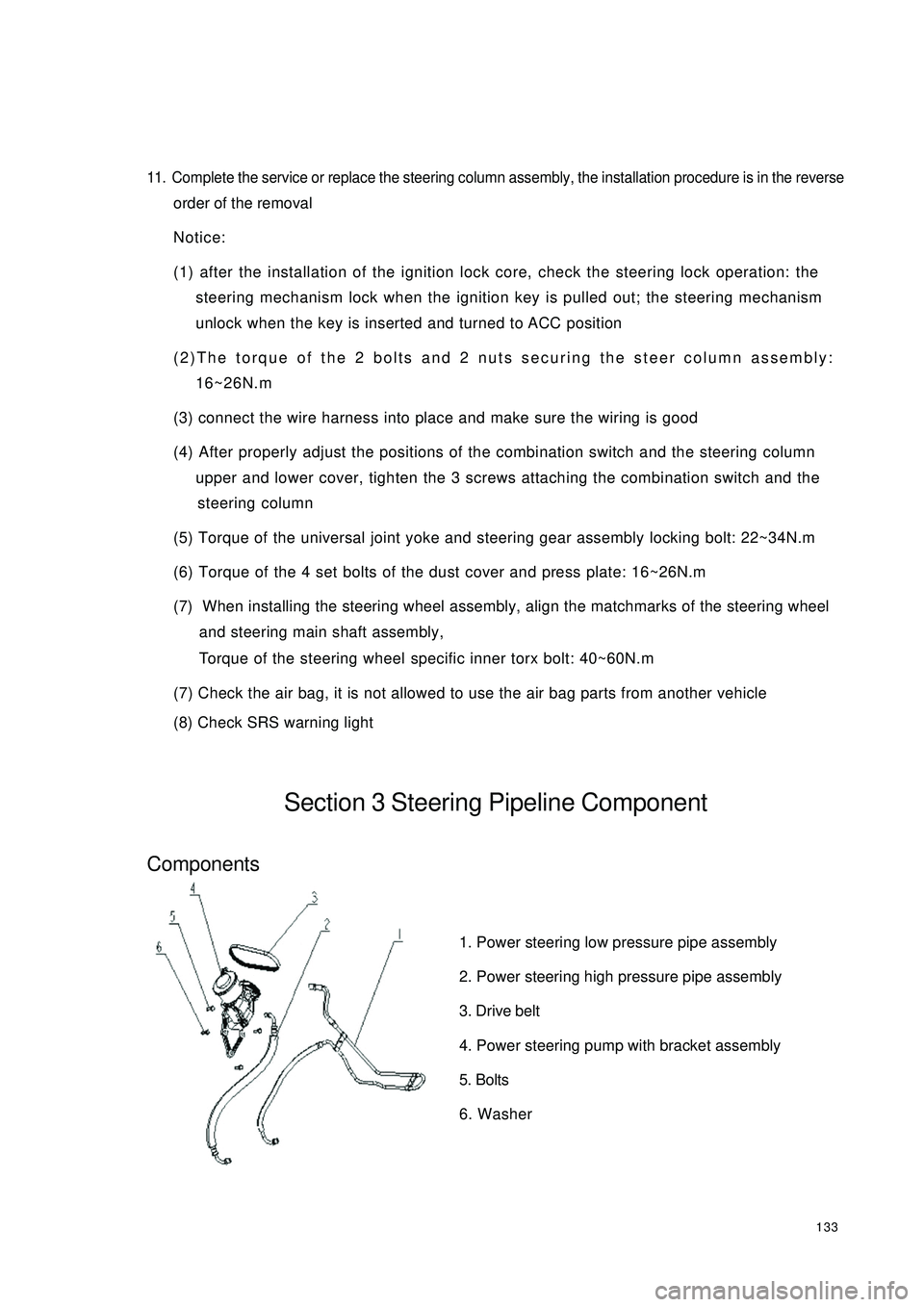
(8) Check SRS warning lightSection 3 Steering Pipeline ComponentComponents1. Power steering low pressure pipe assembly
2. Power steering high pressure pipe assembly
3. Drive belt
4. Power steering pump with bracket assembly
5. Bolts
6. Washer
Page 164 of 392
157Part III Electrical EquipmentChapter 1 SurveyThis part refers to the electrical repair of the Free Cruiser, and analyzes the faults from every system. Then
some practicable diagnosis procedure and repair ways are given.I. HAND-HELD TESTER1. Before the tester is used, a through reading of the Tester Operation Manual is commended.
2. Connect the tester to the diagnosis interface with a wire. Turn the ignition switch ON. At this time, if the
tester and ECU control system cannot communicate, the vehicle or the tester may have faults.
(1) Connect the tester lead wire to another vehicle. If the communication is normal, inspect the vehicle
diagnosis Busline or power supply circuit.
(2) If it still cannot communicate when connecting to the other vehicles, it may have faults on tester itself.
Consult the self-inspecting procedure described on the Tester Operation ManualII. HOW TO PROCEED WITH TROUBLESHOOTINGThe basic operation procedure for troubleshooting is as follows.
1. Customer fault analysis
(a) Ask the customer for the conditions and environment when faults happen.
2. Confirm the fault symptoms, and check the DTCs and storage data.
(a) Check the battery positive voltage (Voltage: 10 - 14V when the engine is stopped.)
(b) Inspect the harness, connector and fuse for open and short, etc. by their appearance.
(c) Warm up the engine temperature to the normal operation temperature.
(d) Confirm the fault symptoms and check the DTCs.
(e) Confirm the test procedure for the parts or systems that need checking.
3. Circuit or part inspection
4. Repair
5. Test for checking
(a) After the repair is completed, verify if the fault has been removed.
(If the fault has not appeared yet, a verifying test should be done under the same conditions and environment
when the fault first occurred.)
Page 169 of 392
1622. INSPECT STARTER NO-LOAD
(a) Connect the magnet exciting coil and the terminal.
(b) Connect the ammeter and the battery to the starter
as shown.
(c) Check that the starter rotates smoothly and steadily
with the clutch pinion gear moving out.
(d) Check that the ammeter shows the specified
current.
Specified current: 90 A or less at 11.5 V
if the current is not normal, replace the starter.
3. WIRING
(a) Check that the connecting wire between
the positive (+) and the starter is stable
and reliable, and the insulating bush is in
good condition, in order to avoid a fire
caused by electric spark.
(b) Check that there is continuity in the wire
and if the insulating bush is not damaged.
If the harness is damaged, replace it.AmmeterIgnition SwitchBattery Main Fuse BoxStarter
Page 173 of 392
166II. CHARGING SYSTEM INSPECTION1. CHECK BATTERY WORKING VOLTAGE
(a) After having driven the vehicle and in the case that 20 minutes have not passed after having stopped the
engine, turn the ignition switch ON and turn on the electrical system (headlight, blower motor) for 60
seconds to remove the surface charge.
(b) Turn the ignition switch OFF and
turn off the electrical systems. Then
measure the battery voltage
between the negative and positive
terminals of the battery.
Standard voltage: 12.5-12.9V at
20°C
HINT:
If the voltage is less than specification, charge the battery.
2. CHECK BATTERY TERMINALS, FUSE BOX AND FUSE
(a) Check that the battery terminals are not loose or corroded.
(b) Check if fuse box and fuse for continuity.