Page 148 of 392

141Section 3 Brake PedalComponents1. Vacuum Booster Assembly
2. Liner
3. Spacer
4. Torsion Spring
5. Brake Pedal Arm
6. Cushion Gasket
7. Brake Pedal MatReplacement:1. Separate the vacuum booster with brake master cylinder assembly
Remove the cotter pin, flat washer and pivot, separate the vacuum booster with brake master cylinder
assembly from the brake pedal
2. Remove the clutch and brake pedal assembly
(1) Remove 4 nuts connecting the vacuum booster with brake master cylinder assembly and brake
pedal support bracket.
(2) Remove 3 bolts connecting the clutch and brake pedal assembly and front cowl panel cross member.
Remove the clutch and brake pedal assembly.
3.Remove the brake pedal
Remove the bolt and nut, Torsion Spring, liner, brake pedal arm assembly , spacer
4. Remove the brake pedal arm assembly
Remove brake pedal mat and cushion gasket from the brake pedal arm.
5. The installation is in the reverse order of removal.
Notice:
(1) Apply No 3 molybdenum disulphide lithium base grease to the relatively moving faces.
(2) After assembling the brake pedal and the brake pedal support bracket, make sure the
brake pedal can turn freely.NutBoltBrake Pedal BracketBrake Pedal
Page 149 of 392

142(3) The 3 bolts connecting the brake pedal support bracket and cowl panel cross member
Torque : 16-20N.m
(4) The 4 bolts connecting the brake pedal support bracket and the vacuum booster with
brake master cylinder assembly
Torque: 16-20N.mCheck the brake pedal1. Check and adjust brake pedal height
(a) Brake pedal height from the ground: normal height is 176~181 mm.
(b) Adjust brake pedal height
(1) Loosen the brake lamp switch lock nut
(2) Adjust the brake lamp switch to the right position
(3) Check the brake lamp switch
Make sure the brake lamp is light by depressing the brake pedal for5~15mm
(4) Tighten the brake lamp switch lock nut
2. Check pedal freestroke
(1) Shut off the engine and depress the brake pedal several times until there is no more vacuum left in
the booster.
(2) Depress the pedal until the resistance begins to be felt
Pedal freestroke should be: 10~30mmWorn Or DamagedWorn Or DamagedWorn Or
DamagedWorn Or
DamagedWorn Or DamagedWorn Or DamagedDistorted Or DamagedDistorted Or DamagedBent Or DistortedFreestroke
Page 150 of 392

143Section 4 Vacuum Booster with Brake Master Cylinder AssemblyNotice: The vacuum booster with brake master cylinder assembly must be repaired by
manufacturer. Replace it if it is faulty.On-vehicle inspection1. Check vacuum booster
(a) Air tightness check
(1) start the engine, run 1 or 2 minutes then shut off. Depress the brake pedal several times slightly.
Hint: if the pedal rises gradually after depressing the pedal, the booster is airtight.
(2) Depress the brake pedal while the engine is running, and stop the engine with the pedal depressed.
Hint: if there is no change in the pedal reserve stroke after holding the pedal for 30 seconds,
the booster is air--tight.
(b) Operating check
Depress the brake pedal and start the engine. If the pedal goes down slightly, operation is normal.
2. Check the vacuum check valve
(1) Remove the connecting pipe with the check valve
(2) Check the direction from the booster to the engine. Check valve for ventilation. It should not
ventilate in the reverse order.
(3) Replace it if it is faulty.
Notice: Pay attention to the matchmark on the connecting hose when connecting
the hose with vacuum check valve. Do not install it in reverse order.Replacement1. Remove the brake pipe on the brake master cylinder (master cylinder)
2. Refer to Brake Pedal Replacement for other operation
Notice:
(1) The torque of the union thread on the brake master cylinder (master cylinder )
and brake pipe: 12-16 N.m
(2) Bleed all the air in the brake system after installationGoodPoorThird
Second
First
Page 151 of 392
144Section 5 Front Brake AssemblyComponents
Repairing1. Remove the front wheel
2. Drain the brake fluid. Remove the brake hose
3. Remove the front brake caliper
(1) Remove the brake hose union thread from the front brake cylinder. Disconnect the hose
(2) Remove 2 installing bolts
4. Remove the front brake pad
5. Remove the front left disc caliper
6. Remove the sliding pin bootDisk Brake Wheel
Cylinder BracketSliding Pin BootInner Floating Clip PlateScrew PlugBrake Caliper
HousingInner
DamperInner Pad
Backing
PlateInner PadOuter PadOuter Pad
Backing PlateOuter
DamperOuter Floating
Clip PlateAlarm
PlateWheel
Cylinder
PistonWheel
Cylinder
Piston SealWheel
Cylinder
BootSteel Wire
Snap RingShort Pin
Set BoltShort BushingGuide Boot (II)Splash ShieldFront Ring GearRetaining
RingWheel Hub BoltFront Wheel
Hub Bearing
Wheel HubDisc
Page 152 of 392

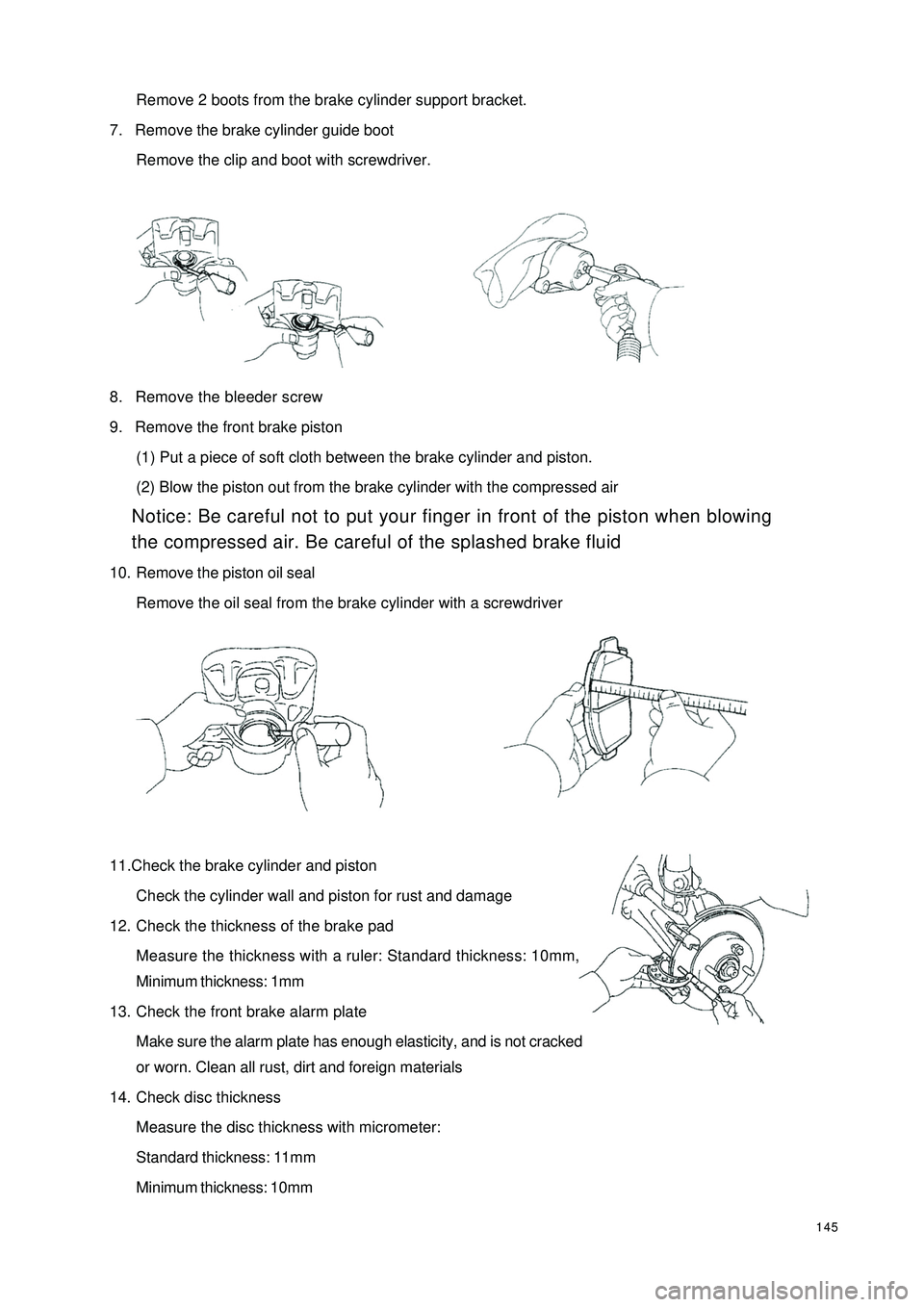
145Remove 2 boots from the brake cylinder support bracket.
7. Remove the brake cylinder guide boot
Remove the clip and boot with screwdriver.
8. Remove the bleeder screw
9. Remove the front brake piston
(1) Put a piece of soft cloth between the brake cylinder and piston.
(2) Blow the piston out from the brake cylinder with the compressed air
Notice: Be careful not to put your finger in front of the piston when blowing
the compressed air. Be careful of the splashed brake fluid
10. Remove the piston oil seal
Remove the oil seal from the brake cylinder with a screwdriver
11.Check the brake cylinder and piston
Check the cylinder wall and piston for rust and damage
12. Check the thickness of the brake pad
Measure the thickness with a ruler: Standard thickness: 10mm,
Minimum thickness: 1mm
13. Check the front brake alarm plate
Make sure the alarm plate has enough elasticity, and is not cracked
or worn. Clean all rust, dirt and foreign materials
14. Check disc thickness
Measure the disc thickness with micrometer:
Standard thickness: 11mm
Minimum thickness: 10mm
Page 153 of 392

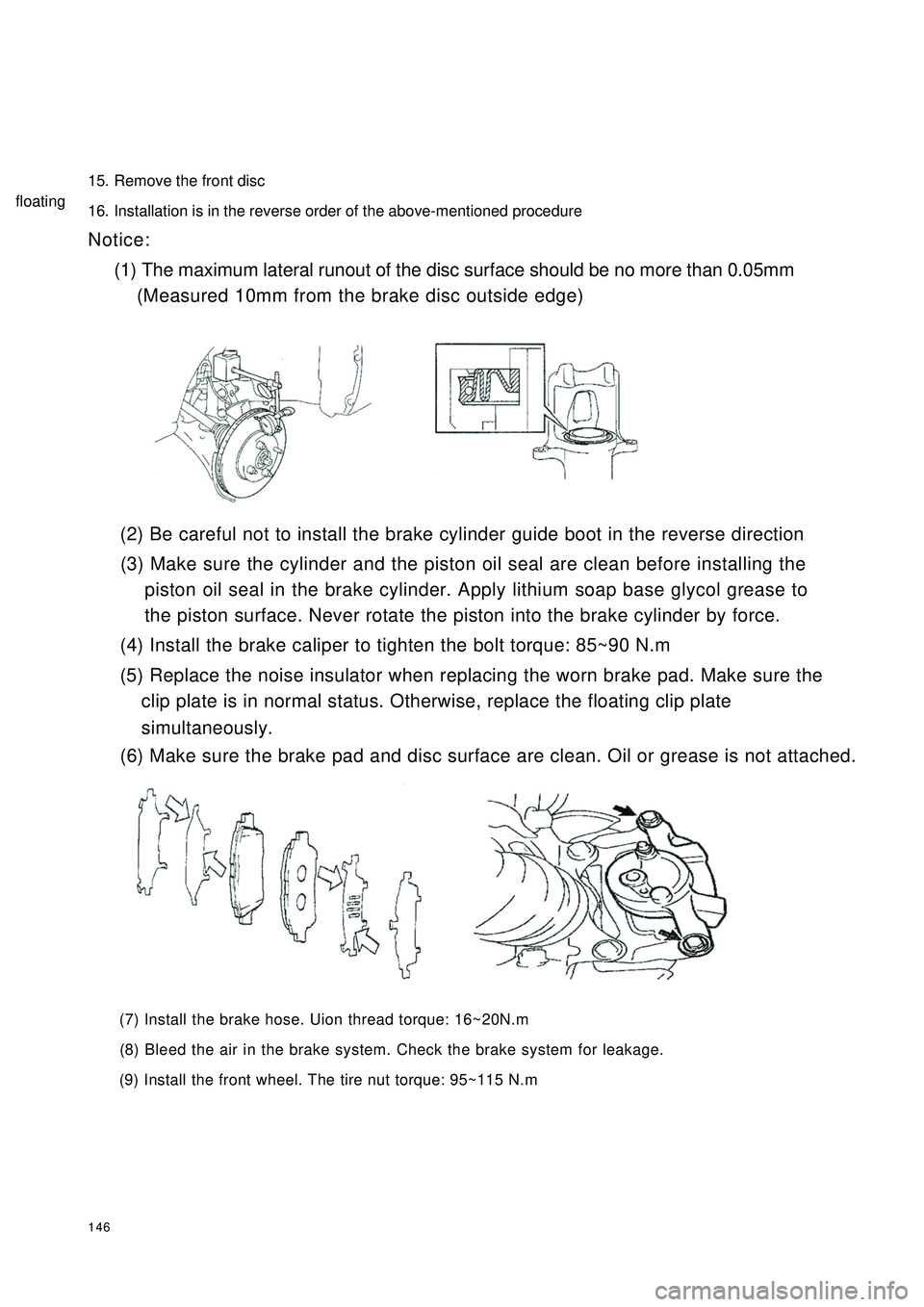
14615. Remove the front disc
16. Installation is in the reverse order of the above-mentioned procedure
Notice:
(1) The maximum lateral runout of the disc surface should be no more than 0.05mm
(Measured 10mm from the brake disc outside edge)
(2) Be careful not to install the brake cylinder guide boot in the reverse direction
(3) Make sure the cylinder and the piston oil seal are clean before installing the
piston oil seal in the brake cylinder. Apply lithium soap base glycol grease to
the piston surface. Never rotate the piston into the brake cylinder by force.
(4) Install the brake caliper to tighten the bolt torque: 85~90 N.m
(5) Replace the noise insulator when replacing the worn brake pad. Make sure the
clip plate is in normal status. Otherwise, replace the floating clip plate
(6) Make sure the brake pad and disc surface are clean. Oil or grease is not attached.
(7) Install the brake hose. Uion thread torque: 16~20N.m
(8) Bleed the air in the brake system. Check the brake system for leakage.
(9) Install the front wheel. The tire nut torque: 95~115 N.msimultaneously.floating
Page 154 of 392
147Section 6 Rear BrakeComponents
Repairing1. Remove rear wheel
2. Drain the brake fluid
3. Remove the brake drum
(1) loose the parking brake handle
(2) Remove the cotter pin with a long nose pliers
(3) loose the spindle slot nut
Lower Return Spring
Oil Baffle Plate
Anchor Plate
Brake Bottom Plates
Left Cable Plate
Left Torsion Spring
Adjusting Pawl Shaft
Pin
Left Adjusting
Pawl
Left Adjusting
Plate
Brake Shoe I
Wheel Hub Bearing II
Rear Spindle Cap
Wheel Hub
Bearing I
Stop Washer
Wheel Hub
Bolt
Rear Ring Gear
Rear Brake Drum
Rear Spindle Cover
Brake Shoe I
Shoe Guide
Friction Shoe
Boot
Cup
Piston
Wheel Cylinder
Spring
Piston
BootCup
Parking Brake
Left Swing Arm
Rear Brake
Auto
Adjusting Lever
Adjusting Lever Spring
Return Spring
Page 155 of 392
148(4) remove the brake drum
4. Measure brake drum inside diameter
Standard inside diameter: 180mm
Maximum inside diameter: 181mm
5. Separate the parking brake left swing arm. Loose the parking brake cable end joint
Separate the parking brake left swing arm. Remove the parking brake cable end joint with a screwdriver.
6. Remove the brake shoe I, brake shoe II
(1) using special tool, remove brake shoe positioning spring and pin
(2) remove brake shoe I and I after separating the return spring
7. Remove the rear brake automatic adjustment lever
Remove the brake adjustment lever spring and adjustment lever
8. Remove the return spring on the brake shoe
Remove the return spring from the brake shoePush