Page 160 of 392
1534. Remove the rear brake hose compo.
Loose the union thread that connects the rear brake hose to LR and RR brake pipe compo., remove the
E-shaped clip on the hose support bracket. Remove the rear brake hose compo.
5. Remove rear left, right brake pipe compo.
(1) Remove a dual tube clip
(2) Remove three 5-pipe clips
(3) Remove rear left, right brake pipe compo.
6. Remove front brake hose assembly
(1) Loose the union thread that connects the front brake hose to LR and RR brake pipe
(2) Remove E-shaped clip on the hose bracket
(3) Loose the union thread that connects the front brake hose to the front brake. Remove the front
brake hose assembly from the front brake
7. Remove the front left, front right brake pipe compo.
8. Remove the No. 1 & 2 brake pipe compo. which connect the brake master cylinder to HECU controller
Page 161 of 392
1549. Remove rear left, right brake pipe No 1 compo.
Loose the union thread that connects the brake pipe compo to HECU controller (ABS module)
10. Separate HECU controller assembly wire harness
11. Remove HECU controller bracket
Remove the 3 hex bolts connecting the bracket and the body
12. Remove HECU controller assembly from the bracket
Using special wrench, remove 3 inner torx bolts and insulator
13. Installation is in the reverse order of the procedure aboveNotice:
(1) The HECU controller bracket to body bolt torque: 20~25N.m
(2) Hose and pipe union thread torque: 12~16N.m
(3) All the hose, pipe should be fixed. The distorted clamp and E-shaped clip should
be replaced. Never interfere the hoses and pipes with other parts.
(4) Bleed the brake system
(5) Check the pipeline and the pipe union for leakage
(6) Inspect HECU control system with ABS diagnosis tester
Page 164 of 392

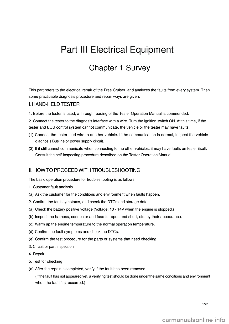
157Part III Electrical EquipmentChapter 1 SurveyThis part refers to the electrical repair of the Free Cruiser, and analyzes the faults from every system. Then
some practicable diagnosis procedure and repair ways are given.I. HAND-HELD TESTER1. Before the tester is used, a through reading of the Tester Operation Manual is commended.
2. Connect the tester to the diagnosis interface with a wire. Turn the ignition switch ON. At this time, if the
tester and ECU control system cannot communicate, the vehicle or the tester may have faults.
(1) Connect the tester lead wire to another vehicle. If the communication is normal, inspect the vehicle
diagnosis Busline or power supply circuit.
(2) If it still cannot communicate when connecting to the other vehicles, it may have faults on tester itself.
Consult the self-inspecting procedure described on the Tester Operation ManualII. HOW TO PROCEED WITH TROUBLESHOOTINGThe basic operation procedure for troubleshooting is as follows.
1. Customer fault analysis
(a) Ask the customer for the conditions and environment when faults happen.
2. Confirm the fault symptoms, and check the DTCs and storage data.
(a) Check the battery positive voltage (Voltage: 10 - 14V when the engine is stopped.)
(b) Inspect the harness, connector and fuse for open and short, etc. by their appearance.
(c) Warm up the engine temperature to the normal operation temperature.
(d) Confirm the fault symptoms and check the DTCs.
(e) Confirm the test procedure for the parts or systems that need checking.
3. Circuit or part inspection
4. Repair
5. Test for checking
(a) After the repair is completed, verify if the fault has been removed.
(If the fault has not appeared yet, a verifying test should be done under the same conditions and environment
when the fault first occurred.)
Page 165 of 392

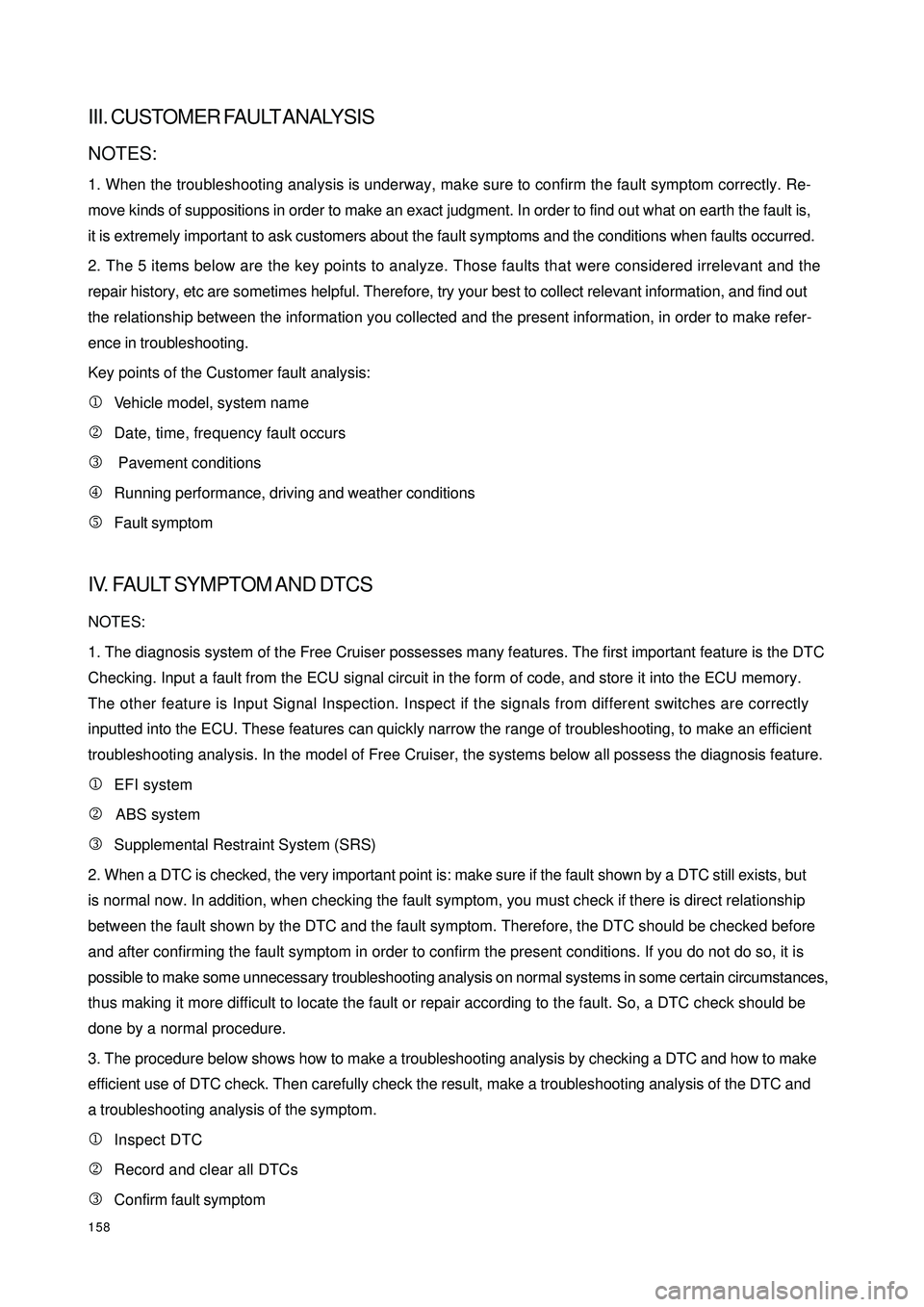
158III. CUSTOMER FAULT ANALYSISNOTES:
1. When the troubleshooting analysis is underway, make sure to confirm the fault symptom correctly. Re-
move kinds of suppositions in order to make an exact judgment. In order to find out what on earth the fault is,
it is extremely important to ask customers about the fault symptoms and the conditions when faults occurred.
2. The 5 items below are the key points to analyze. Those faults that were considered irrelevant and the
repair history, etc are sometimes helpful. Therefore, try your best to collect relevant information, and find out
the relationship between the information you collected and the present information, in order to make refer-
ence in troubleshooting.
Key points of the Customer fault analysis:
1Vehicle model, system name
2Date, time, frequency fault occurs
3 Pavement conditions
4Running performance, driving and weather conditions
5Fault symptomIV. FAULT SYMPTOM AND DTCSNOTES:
1. The diagnosis system of the Free Cruiser possesses many features. The first important feature is the DTC
Checking. Input a fault from the ECU signal circuit in the form of code, and store it into the ECU memory.
The other feature is Input Signal Inspection. Inspect if the signals from different switches are correctly
inputted into the ECU. These features can quickly narrow the range of troubleshooting, to make an efficient
troubleshooting analysis. In the model of Free Cruiser, the systems below all possess the diagnosis feature.
1EFI system
2 ABS system
3Supplemental Restraint System (SRS)
2. When a DTC is checked, the very important point is: make sure if the fault shown by a DTC still exists, but
is normal now. In addition, when checking the fault symptom, you must check if there is direct relationship
between the fault shown by the DTC and the fault symptom. Therefore, the DTC should be checked before
and after confirming the fault symptom in order to confirm the present conditions. If you do not do so, it is
possible to make some unnecessary troubleshooting analysis on normal systems in some certain circumstances,
thus making it more difficult to locate the fault or repair according to the fault. So, a DTC check should be
done by a normal procedure.
3. The procedure below shows how to make a troubleshooting analysis by checking a DTC and how to make
efficient use of DTC check. Then carefully check the result, make a troubleshooting analysis of the DTC and
a troubleshooting analysis of the symptom.
1Inspect DTC
2Record and clear all DTCs
3Confirm fault symptom
Page 167 of 392
1603. Way of Heating: When getting warm in the suspected area may be the major cause of the fault.
(a) Use a drier or other similar tool to heat the suspected area to check if the fault occurs.
NOTES:
�yThe heating temperature must be less than 60¡æ £¨140¨H£©(The temperature shall not exceed
the one that can damage the component.)
�yDo not directly heat the ECU parts.
4. Another way: When electrical overload may be the major cause of the fault.
�y Connect all electrical loads to check if the fault occurs.
Page 188 of 392
1813. TACHOMETER MALFUNCTION
CIRCUIT DIAGRAM
Inspection procedure
(a) Inspect the combination meter assembly revolution input signal
1Remove the combination meter assembly and retain the connection of connectors.
2Connect the oscilloscope to the terminal B11 and
ground.
3Start the engine
4Inspect the signal wave form
Standard:
Show the correct wave form
Result and solution:
NormalInspect and replace the combination
meter assembly
AbnormalInspect the engine ECU revolution out-
put signalEngine ECUCombined Meter Assembly
Engine Revolution Signal
Page 189 of 392
182(b) Inspect the engine ECU revolution output signal
1Remove the engine ECU and retain the connection of connectors.
2Connect the oscilloscope to the terminal 54 and ground.
3Start the engine
4Inspect the signal wave form
Standard:
Show the correct wave form
Result and solution:
NormalRepair or replace the harness or
connector
AbnormalInspect the engine control system
Page 249 of 392

242Chapter 7
SRS (Supplemental Restraint System)Section 1 SRS-General InformationI. PRECAUTIONFor safe reasons, read the following precautions before starting any operation.
1. When servicing the SRS, correct sequence and items are described in the following chapter.
2. Instruments and special tools recommended in this chapter shall be used for operation.
3. When servicing the following components, replace them with the new ones if there is a failure.
(1) SRS ECU
(2) Clock Spring Module
(3) Driver Airbag Module
(4) Passenger Airbag Assembly (Option)
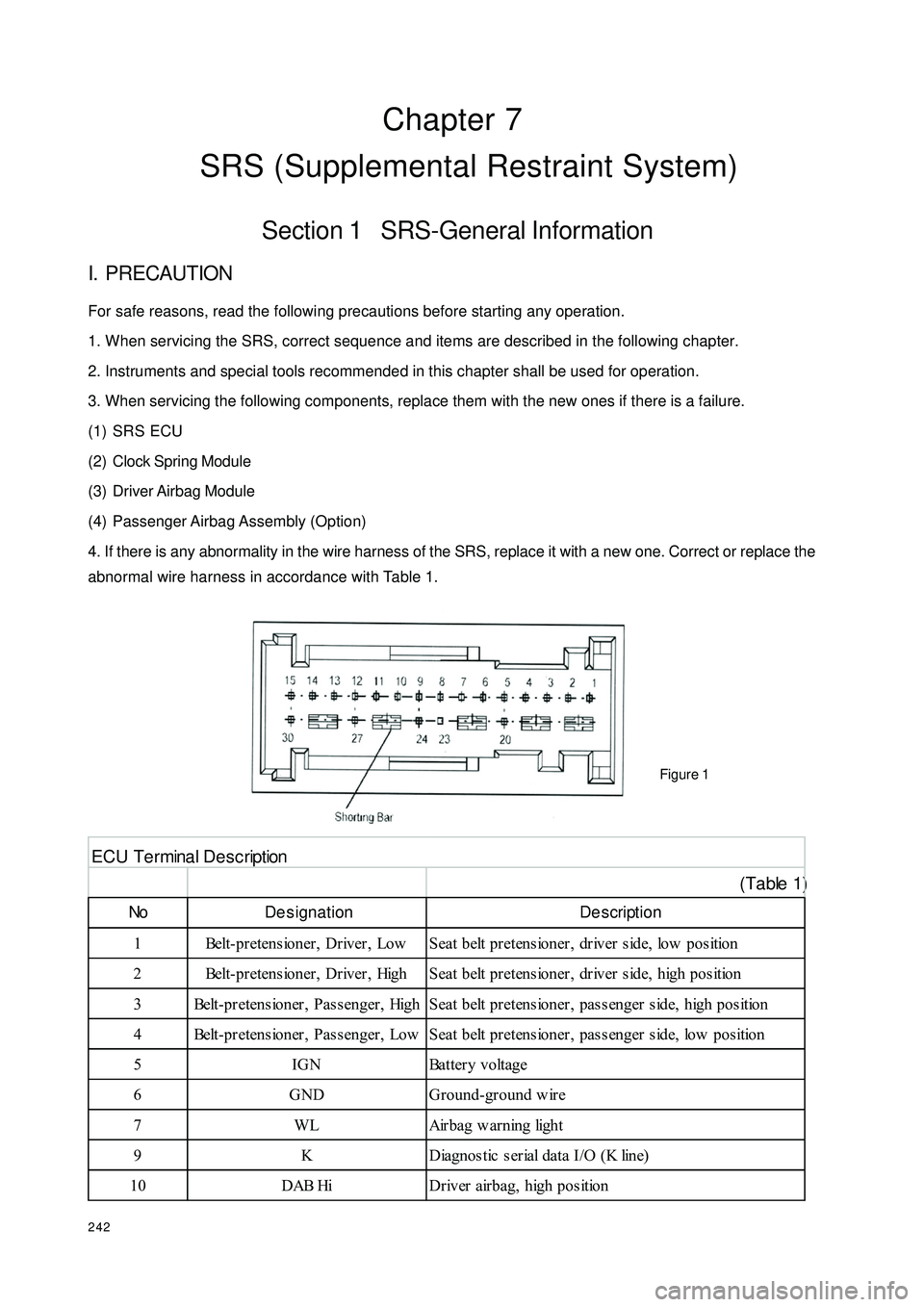
4. If there is any abnormality in the wire harness of the SRS, replace it with a new one. Correct or replace the
abnormal wire harness in accordance with Table 1.
Figure 1 (Table 1)No De signation De scription
1 Belt-pretensioner, Driver, Low Seat belt pretensioner, driver side, low position
2 Belt-pretensioner, Driver, High Seat belt pretensioner, driver side, high position
3 Belt-pretensioner, Passenger, High Seat belt pretensioner, passenger side, high position
4 Belt-pretensioner, Passenger, Low Seat belt pretensioner, passenger side, low position
5 IGN Battery voltage
6 GND Ground-ground w ire
7 WL Airbag w arning light
9 K Diagnostic serial data I/O (K line)
10 DAB Hi Driver airbag, high positionE C U T e r mina l D e s c r ipt ion