Page 40 of 392
33Section 6 Oil Pump Oil Seal Replacement1. Pry with 2 screwdrivers. Detach crankshaft timing pulley.
See (Figure 74)
2. Remove oil pump oil seal. See (Figure 75)
(a) Using a knife, cut off oil seal lip.
(b) Using a screwdriver, pry out the oil seal.
3. Install oil pump oil seal. See (Figure 76)
(a) Smear grease to a new oil seal lip.
(b) on the oil seal with hammer until the edge of the oil pump
case is filled with the seal packing.
4. Install crankshaft timing pulley. See (Figure 77)
(a) Align pulley set key to the key groove.
(b) Place the flange face inward. Install timing pulley.
5. Install timing belt
6. Check engine oil for leakage
Figure 76 Figure 74
Figure 75
Figure 77
Page 42 of 392
35Chapter 3 Lubrication System
(MR479Q, MR479QA, MR481QA)Section 1 Oil Pressure Gage Sensor Replacement1. Check oil level
Warm up the engine. Check the dipstick to ensure oil level between "L" and "F" after engine stopped
5 minutes. Check for leakage if it is too low. Fill oil to "F.
2. Check oil for deterioration. Water entry, discolor and dilution. Replace oil if it is obviously
deteriorated.
3. Detach oil pressure sensor assembly. See (Figure 80)
4. Install oil pressure gage sensor. See (Figure 81) Start engine to
normal operation temperature.
5. Check for oil pressure
6. Smear adhesive on 2 or 3 threads of the oil pressure sensor.
Install oil pressure sensor. See (Figure 82)
Figure 81
Figure 82Figure 80
Page 44 of 392
3713. Install the dipstick guide. See (Figure 87)
14. Install crankshaft timing pulley. See (Figure 77)
15. Install timing belt idler sub-assembly No.1
16. Install timing belt
17. Fill in engine oil
18. Check oil for leakage
Figure 87
Page 48 of 392

41Chapter 4 Fuel System
(MR7131A, MR7151A, MR7161A)Section 1 Check Fuel System Pressure1. Remove the fuel tank from the vehicle
2. Check the fuel pump running
(a) Connect the positive and negative battery terminal to the concerned
fuel pump connector. See (Figure 91).
Notice: Do not start engine
The sound of fuel flowing can be heard if there is pressure.
Check fusible link, fuse, EFI open circuit relay, fuel pump, ECU and
wire connector if there is no pressure.
(b) Turn the ignition switch to "OFF" position.
3. Check fuel pressure
(a) Check battery electrical pressure to be above 12V.
(b) Detach negative terminal cable from the battery.
(c) Install pressure gage from the fuel delivery pipe. See (Figure 92).
(d) Connect battery negative terminal.
(e) Measure fuel pressure
Fuel pressure:
304-343kPa
Check fuel pipe & union, fuel pump, fuel filter if the pressure is too
low.
(f) Start engine. Measure fuel pressure at idle. Fuel pressure: 304-343kPa
(g) Check fuel pressure and retain the pressure for approximately 5min after the engine stopped.
Fuel pressure: 147kPaFigure 91Figure 92
Page 54 of 392

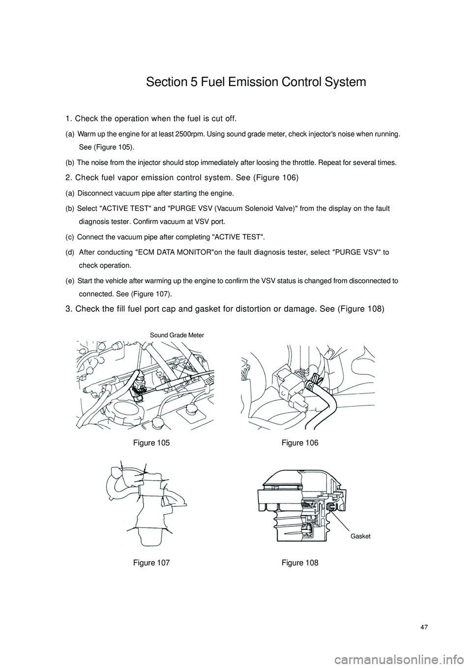
47Section 5 Fuel Emission Control System1. Check the operation when the fuel is cut off.
(a) Warm up the engine for at least 2500rpm. Using sound grade meter, check injector's noise when running.
See (Figure 105).
(b) The noise from the injector should stop immediately after loosing the throttle. Repeat for several times.
2. Check fuel vapor emission control system. See (Figure 106)
(a) Disconnect vacuum pipe after starting the engine.
(b) Select "ACTIVE TEST" and "PURGE VSV (Vacuum Solenoid Valve)" from the display on the fault
diagnosis tester. Confirm vacuum at VSV port.
(c) Connect the vacuum pipe after completing "ACTIVE TEST".
(d) After conducting "ECM DATA MONITOR"on the fault diagnosis tester, select "PURGE VSV" to
check operation.
(e) Start the vehicle after warming up the engine to confirm the VSV status is changed from disconnected to
connected. See (Figure 107).
3. Check the fill fuel port cap and gasket for distortion or damage. See (Figure 108)
Figure 105 Figure 106
Figure 107 Figure 108Sound Grade Meter
Gasket
Page 59 of 392

52Chapter 6 Cooling System Inspection
(MR7131A, MR7151A, MR7161A)Section 1 System Check1. Check the cooling system for leakage. See (Figure 118)
(a) Fill coolant into radiator. Install the tester onto the radiator cap port.
(b) Start engine.
(c) The water pump pressure is 118Kpa. Check the pressure and ensure the
pressure will not drop. If the pressure drops, check the port, radiator and
water pump for leakage. If there is no leakage, check the heat exchanger,
cylinder block and cylinder head.
2. Check the engine coolant level in the reservoir.
The coolant level should be between low and full marks.
3. Check coolant quality
(a) Remove radiator cap.
To avoid being scalded, do not remove radiator cap while the engine and
radiator are still hot, as fluid and steam can be sprayed under pressure.
(b) There should not be excessive deposits of rust or scale around the radiator,
and the coolant should be free from oil.
(c) Reinstall the radiator cap.
4. Thermostat
Hint:
The thermostat temp indicates the valve opening temperature.
See (Figure 119).
(a) Immerse the thermostat in water and gradually heat the water.
(b) Check the valve opening temperature. Valve opening temperature: 80 -- 84°C
(c) Check the valve lift. See (Figure 120, Figure 121). Valve lift: 8mm or mor at
95°C
(d) Check the thermostat is fully closed when the thermostat is at low temperature
( 77°C).
5. Radiator cap valve
Standard opening pressure: 93-123kpa
Minimum opening pressure: 78kpa
If the opening pressure is less thanminimum, replace the radiator cap.Figure 118
Figure 119
Figure 120
Figure 121 Radiator Cap Tester8.0mm or
More ≤
Page 60 of 392

536. Fan
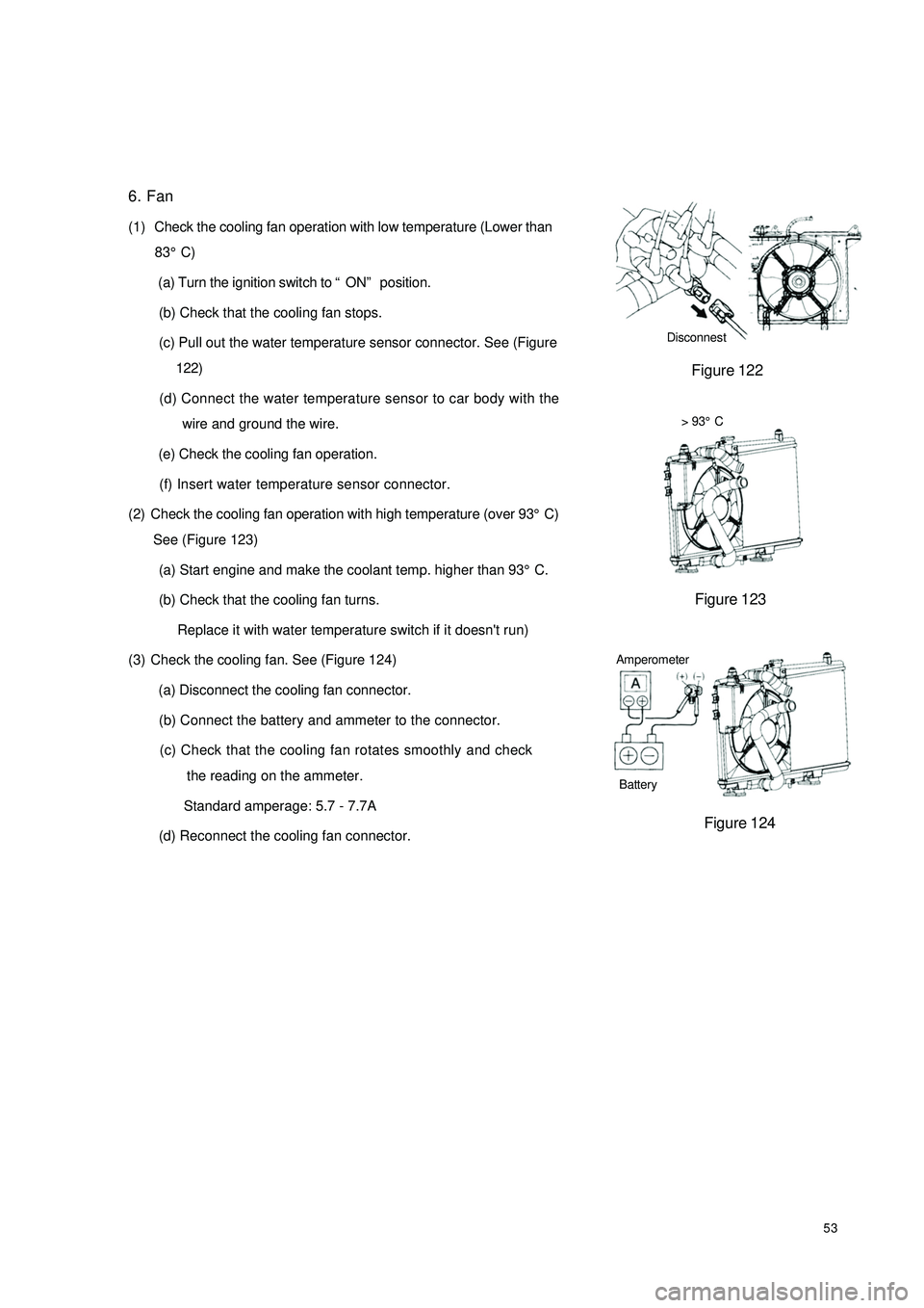
(1) Check the cooling fan operation with low temperature (Lower than
83°C)
(a) Turn the ignition switch to “ON” position.
(b) Check that the cooling fan stops.
(c) Pull out the water temperature sensor connector. See (Figure
122)
(d) Connect the water temperature sensor to car body with the
wire and ground the wire.
(e) Check the cooling fan operation.
(f) Insert water temperature sensor connector.> 93°C
See (Figure 123)
(a) Start engine and make the coolant temp. higher than 93°C.
(b) Check that the cooling fan turns.
Replace it with water temperature switch if it doesn't run)
(3) Check the cooling fan. See (Figure 124)
(a) Disconnect the cooling fan connector.
(b) Connect the battery and ammeter to the connector.
(c) Check that the cooling fan rotates smoothly and check
the reading on the ammeter.
Standard amperage: 5.7 - 7.7A
(d) Reconnect the cooling fan connector.Disconnest
Figure 123
Figure 124 Figure 122
(2) Check the cooling fan operation with high temperature (over 93°C)Battery Amperometer
Page 64 of 392
57Section 1 Clutch ReplacementHoist the engine from the compartment. See "Provison 20, Section 2, Chapter 2".
1. Remove manual transaxle assembly
2. Remove the clutch release fork. See (Figure 132)
3. Detach clutch release fork boot.
4. Detach clutch release bearing
5. Detach clutch release bearing fixed clamp
6. Remove clutch fork pivot pin
7. Align the clutch cover to the mark on the flywheel. Detach clutch cover. See (Figure 133)
8. Remove clutch plate
9. Check and remove clutch plate assembly. See (Figure 134)
10. Check clutch cover. See (Figure 135)
Depth wear: A: 0.6mm
Width wear: B: 5mm
Figure 132 Figure 133
Figure 134 Figure 135