Page 165 of 278

Downloaded from www.Manualslib.com manuals search engine Manoeuvring with theparking aid
CAUTIONS
The parking aid does not detectobstacles moving away from thevehicle. They will only be detectedshortly after they start to movetowards the vehicle again.
Take particular care whenreversing with a tow ball arm orrear fitted accessories e.g. a bicyclecarrier, as the rear parking aid will onlyindicate the distance from thebumper to the obstacle.
Note:If a high pitch warning tonesounds for three seconds and thelight in the switch is flashing, itindicates a malfunction. The systemwill be disabled. Have the systemchecked by properly trainedtechnicians.
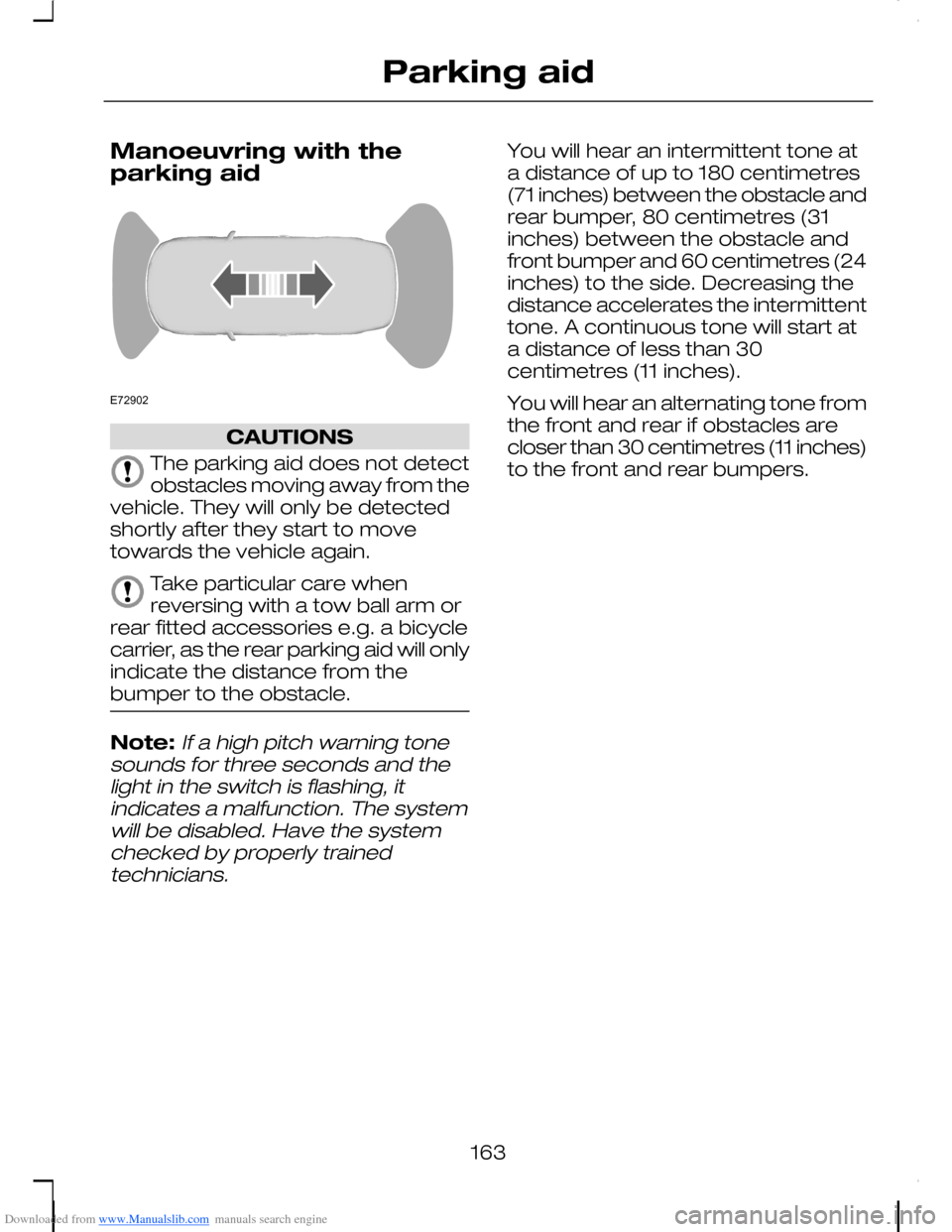
You will hear an intermittent tone ata distance of up to 180 centimetres(71 inches) between the obstacle andrear bumper, 80 centimetres (31inches) between the obstacle andfront bumper and 60 centimetres (24inches) to the side. Decreasing thedistance accelerates the intermittenttone. A continuous tone will start ata distance of less than 30centimetres (11 inches).
You will hear an alternating tone fromthe front and rear if obstacles arecloser than 30 centimetres (11 inches)to the front and rear bumpers.
163
Parking aidE72902
Page 171 of 278

Downloaded from www.Manualslib.com manuals search engine TOWING A TRAILER
WARNINGS
Do not exceed the maximumvehicle and trailer weight statedon the vehicle identification plate. SeeVehicle identification (page 226).
ST vehicles are not approvedfor trailer towing.
Note:Not all vehicles are suitable orapproved to have tow bars fitted.Check with your dealer first.
Place loads as low and central to theaxle(s) of the trailer as possible. If youare towing with an unladen vehicle,the load in the trailer should beplaced toward the nose, within themaximum nose load, as this gives thebest stability.
Note:The maximum trailer noseweight can be found on themanufacturers data plate on the towbar.
The stability of the vehicle to trailercombination is very much dependanton the quality of the trailer.
In high altitude regions, the stipulatedmaximum permitted gross trainweight must be reduced by 10% forevery 1 000 metres (3 281 feet).
Steep gradients
WARNING
The overrun brake on a trailer isnot controlled by ABS.
Change down a gear before youreach a steep downhill gradient.
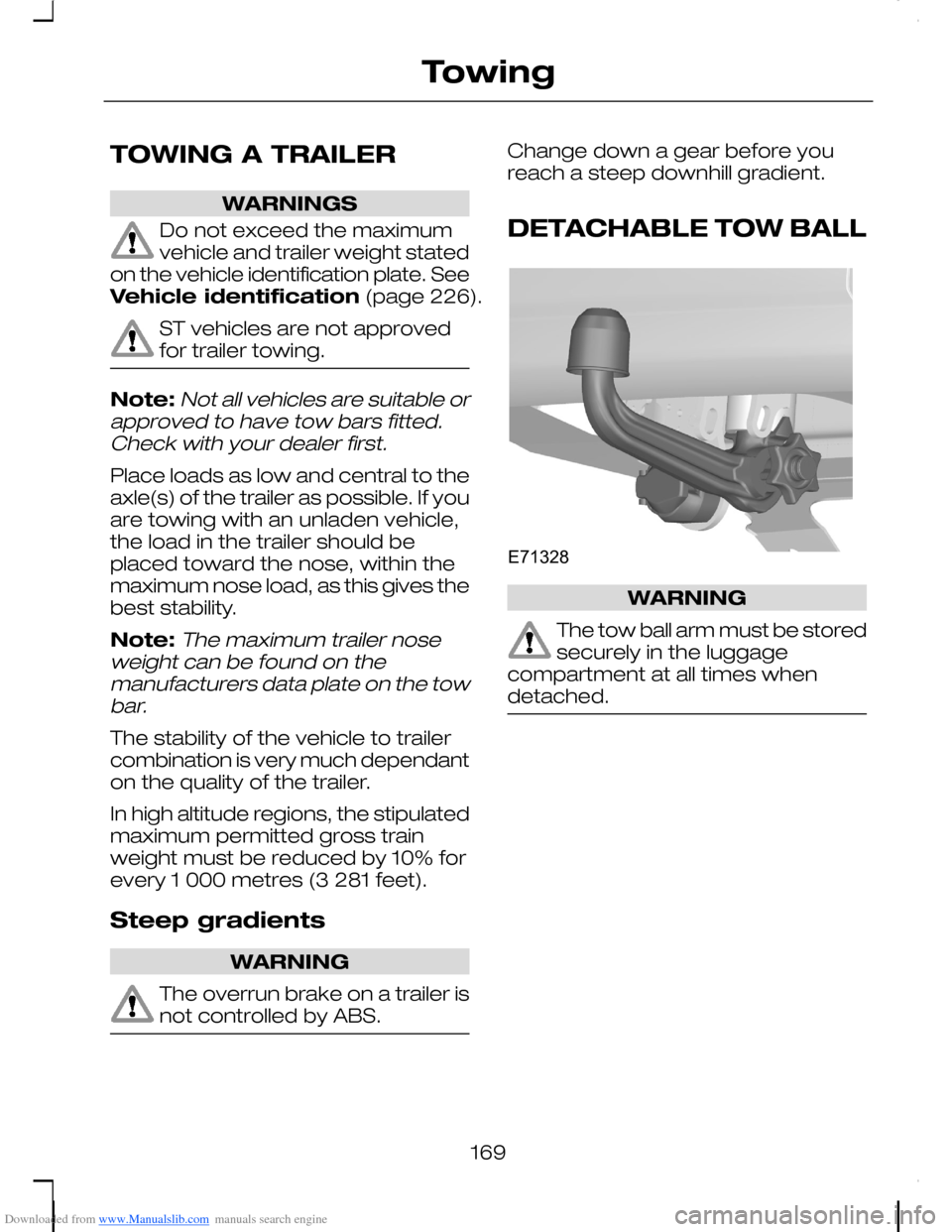
DETACHABLE TOW BALL
WARNING
The tow ball arm must be storedsecurely in the luggagecompartment at all times whendetached.
169
TowingE71328
Page 173 of 278

Downloaded from www.Manualslib.com manuals search engine 1.Insert the tow ball arm verticallyand press it upwards until itengages. Do not hold your handnear the handwheel.
2.To lock: Turn the key clockwiseand remove the key.
Insert the end of the protection capinto the keyhole.
Driving with a trailer
WARNING
If any of the below conditionscannot be met, do not use thetow bar and have it inspected by anexpert.
Before starting your journey, ensurethe tow ball arm is properly locked.Check that:
•The green mark on thehandwheel is next to the white doton the tow ball arm.
•The handwheel A is pushed inagainst the tow ball arm.
•The key B has been removed.
•Secure positioning of the towballarm. (Must remain perfectly inplace when jerked.)
Removing the tow ball arm
1.Remove the protection capcovering the keyhole. Insert thekey and turn it anticlockwise tounlock.
2.Hold the towball arm. Pull out thehandwheel and turn it clockwiseuntil it clicks and pull the towballarm downwards.
3.Remove the tow ball arm.
Release the handwheel.
When unlocked in this way, the towball arm can be reinserted at anytime.
171
TowingE71331AB 31E713322
Page 177 of 278
Downloaded from www.Manualslib.com manuals search engine FUEL CUT-OFF SWITCH
Vehicles with a Duratecengine
The fuel supply may be cut off as aresult of an accident or suddenvibrations (e.g. collision whenparking).
The switch is located in the side panelin front of the left-hand door. Thebutton will be raised when the switchis activated.
Resetting the switch
WARNING
Do not reset the fuel cut-offswitch if you see or smell leakingfuel.
•Turn the ignition switch to position0.
•Check fuel system for leaks.
•If no fuel leak is apparent, resetthe switch by pushing in thebutton (see illustration).
•Turn the ignition switch to positionII. After a few seconds return thekey to position I.
•Make a further check for leaks inthe fuel system.
INSPECTING SAFETY
SYSTEM COMPONENTS
Seat belts
Belts subjected to strain, as a resultof an accident, should be renewedand the anchorages checked by aproperly trained technician.
175
Status after a collisionE72531
Page 190 of 278

Downloaded from www.Manualslib.com manuals search engine GENERAL INFORMATION
Have your vehicle serviced regularlyto help maintain its roadworthinessand resale value. There is a largenetwork of Ford Authorised Repairersthat are there to help you with theirprofessional servicing expertise. Webelieve that their specially trainedtechnicians are best qualified toservice your vehicle properly andexpertly. They are supported by awide range of highly specialised toolsdeveloped specifically for servicingyour vehicle.
In addition to regular servicing, werecommend that you carry out thefollowing additional checks.
WARNINGS
Switch the ignition off beforetouching or attemptingadjustment of any kind.
Do not touch the electronicignition system parts after youhave switched the ignition on orwhen the engine is running. Thesystem operates at high voltage.
Keep your hands and clothingclear of the engine cooling fan.Under certain conditions, the fan maycontinue to run for several minutesafter you have switched the engineoff.
Daily checks
•Exterior lamps.
•Interior lamps.
•Warning lamps and indicators.
Check when refuelling
•Engine oil level. See Engine oilcheck (page 200).
•Brake fluid level. See Brake andclutch fluid check (page 202).
•Washer fluid level. See Washerfluid check (page 203).
•Tyre pressures (when cold). SeeWheels and tyres (page 211).
•Tyre condition. See Wheels andtyres (page 211).
Monthly checks
•Engine coolant level (engine cold).See Engine coolant check(page 201).
•Pipes, hoses and reservoirs forleaks.
•Power steering fluid level. SeePower steering fluid check(page 202).
•Air conditioning operation.
•Parking brake operation.
•Horn operation.
•Tightness of wheel nuts. SeeWheels and tyres (page 211).
188
Maintenance
Page 192 of 278
Downloaded from www.Manualslib.com manuals search engine ENGINE COMPARTMENT OVERVIEW - 1.6L DURATEC-
16V (SIGMA)/1.6L DURATEC-16V TI-VCT (SIGMA)
Screen washer fluid reservoir*: See Washer fluid check (page
203).
A
Engine coolant reservoir*: See Engine coolant check (page 201).B
Brake and clutch fluid reservoir (right-hand drive)*: See Brake and
clutch fluid check (page 202).
C
Engine oil filler cap*: See Engine oil check (page 200).D
190
MaintenanceIJFEDCBAHGE78887
Page 193 of 278
Downloaded from www.Manualslib.com manuals search engine Brake and clutch fluid reservoir (left-hand drive)*: See Brake and
clutch fluid check (page 202).
E
Battery: See Vehicle battery (page 209).F
Auxiliary fuse box: See Fuses (page 176).G
Air cleaner: No maintenance necessary.H
Engine oil dipstick*: See Engine oil check (page 200).I
Power steering fluid reservoir: See Power steering fluid check(page 202).J
*For easy identification, filler caps and the engine oil dipstick are marked in
colour.
191
Maintenance
Page 194 of 278
Downloaded from www.Manualslib.com manuals search engine ENGINE COMPARTMENT OVERVIEW - 1.8L DURATEC-
HE (MI4)/2.0L DURATEC-HE (MI4)
Screen washer fluid reservoir*: See Washer fluid check (page
203).
A
Engine coolant reservoir*: See Engine coolant check (page 201).B
Brake and clutch fluid reservoir (right-hand drive)*: See Brake and
clutch fluid check (page 202).
C
Engine oil filler cap*: See Engine oil check (page 200).D
192
MaintenanceE78889IFEDCBAHG