2008 DODGE RAM 3500 GAS change wheel
[x] Cancel search: change wheelPage 212 of 554

Electrical Disturbances
Radio waves may pick up electrical disturbances during
transmission. They mainly affect the wave amplitude,
and thus remain a part of the AM reception. They
interfere very little with the frequency variations that
carry the FM signal.
TWO TYPES OF SIGNALS
There are two basic types of radio signals: AM or
Amplitude Modulation, in which the transmitted sound
causes the amplitude, or height, of the radio waves to
vary; and FM or Frequency Modulation, in which the
frequency of the wave is varied to carry the sound.
AM Reception
AM sound is based on wave amplitude, so AM reception
can be disrupted by such things as lightning, power lines
and neon signs.
FM Reception
Because FM transmission is based on frequency varia-
tions, interference that consists of amplitude variations
can be filtered out, leaving the reception relatively clear,
which is the major feature of FM radio.
NOTE:The radio, steering wheel radio controls (if
equipped), and six-disc CD/DVD changer (if equipped)
will remain active for up to 10 minutes after the ignition
switch has been turned OFF. Opening a vehicle front
door will cancel this feature.
210 UNDERSTANDING YOUR INSTRUMENT PANEL
Page 257 of 554

Reception Quality
Satellite reception may be interrupted due to one of the
following reasons:
²The vehicle is parked in an underground parking
structure or under a physical obstacle.
²Dense tree coverage may interrupt reception.
²Driving under wide bridges or along tall buildings can
cause intermittent reception.
²Placing objects over or too close to the antenna can
cause signal blockage.
REMOTE SOUND SYSTEM CONTROLS Ð IF
EQUIPPED
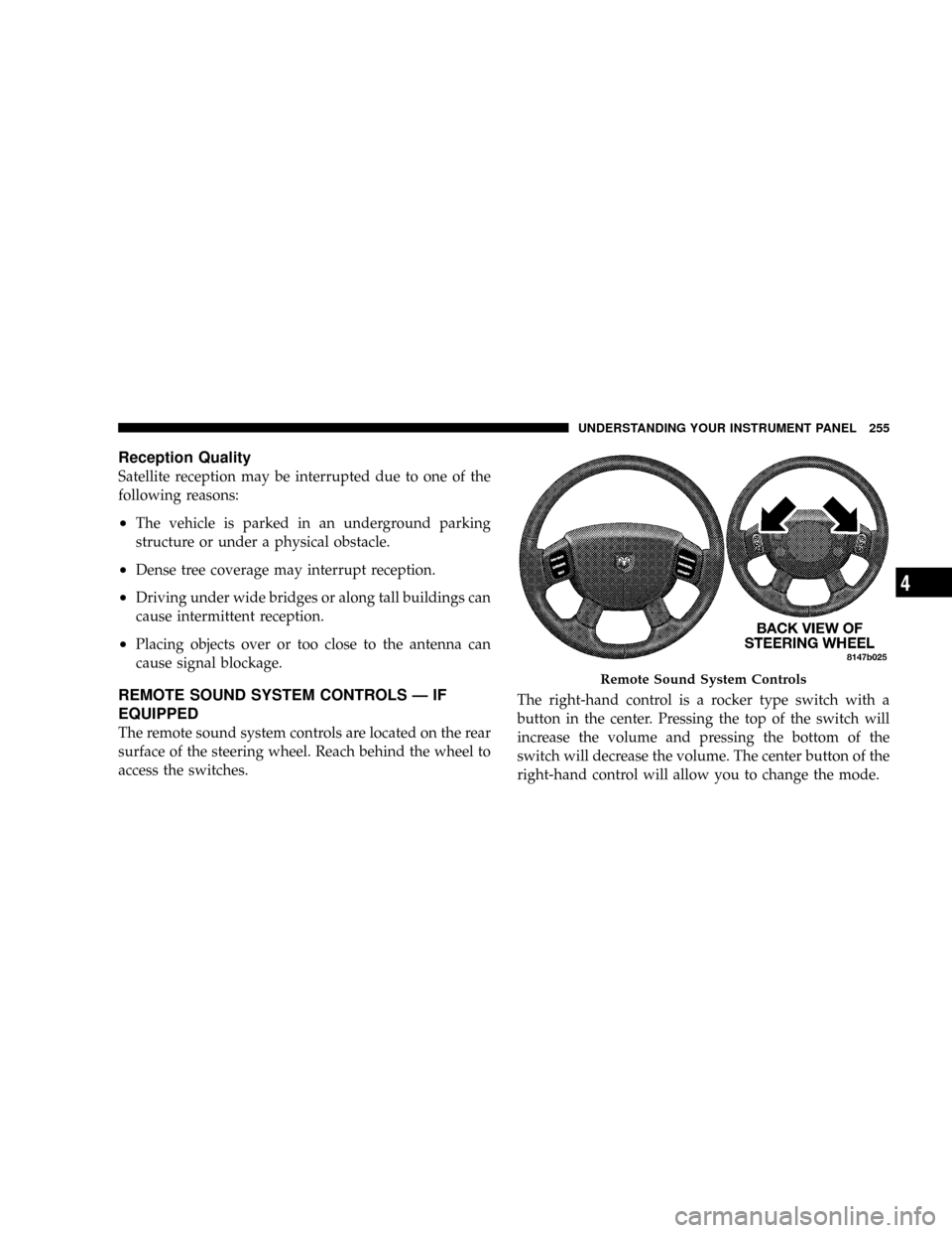
The remote sound system controls are located on the rear
surface of the steering wheel. Reach behind the wheel to
access the switches.The right-hand control is a rocker type switch with a
button in the center. Pressing the top of the switch will
increase the volume and pressing the bottom of the
switch will decrease the volume. The center button of the
right-hand control will allow you to change the mode.
Remote Sound System Controls
UNDERSTANDING YOUR INSTRUMENT PANEL 255
4
Page 334 of 554

Electronic Roll Mitigation (ERM)
The ERM system anticipates the potential for wheel lift
by monitoring the driver 's steering wheel input and the
speed of the vehicle. When ERM determines that the rate
of change of the steering wheel angle and vehicle speed
are sufficient to potentially cause wheel lift, it applies the
appropriate brake and may reduce engine power to
lessen the chance that wheel lift will occur. ERM will only
intervene during very severe or evasive driving maneu-
vers.
ERM can only reduce the chance of wheel lift occurring
during severe or evasive driving maneuvers. It cannot
prevent wheel lift due to other factors such as road
conditions, leaving the roadway or striking objects or
other vehicles.WARNING!
Many factors, such as vehicle loading, road condi-
tions and driving conditions, influence the chance
that wheel lift or rollover may occur.
²ERM cannot prevent all wheel lift or rollovers,
especially those that involve leaving the roadway
or striking objects or other vehicles. Only a safe,
attentive, and skillful driver can prevent accidents.
²The capabilities of an ERM-equipped vehicle
must never be exploited in a reckless or dangerous
manner which could jeopardize the user's safety
or the safety of others.
332 STARTING AND OPERATING
Page 357 of 554

Replacement Tires
The tires on your new vehicle provide a balance of many
characteristics. They should be inspected regularly for
wear and correct cold tire inflation pressure. The manu-
facturer strongly recommends that you use tires equiva-
lent to the originals in size, quality and performance
when replacement is needed. (Refer to the paragraph on
ªTread Wear Indicatorsº). Refer to the ªTire and Loading
Informationº placard for the size designation of your tire.
The service description and load identification will be
found on the original equipment tire. Failure to use
equivalent replacement tires may adversely affect the
safety, handling, and ride of your vehicle. We recommend
that you contact your original equipment or an autho-
rized tire dealer with any questions you may have on tire
specifications or capability.WARNING!
DO NOT use a tire, wheel size or rating other than
that specified for your vehicle. Some combinations of
unapproved tires and wheels may change suspension
dimensions and performance characteristics, result-
ing in changes to steering, handling, and braking of
your vehicle. This can cause unpredictable handling
and stress to steering and suspension components.
You could lose control and have an accident resulting
in serious injury or death. Use only the tire and
wheel sizes with load ratings approved for your
vehicle.
STARTING AND OPERATING 355
5
Page 370 of 554

WARNING!
It is the driver 's responsibility to change to the max
load inflation pressure (cold) low pressure warning
threshold condition when not driving in the light
load condition as defined as two occupants ( 150 lbs
each) plus 200 pounds of cargo. The vehicle ªLight
Load Definitionº is found in the Supplemental Tire
Pressure Information label located on the rear face of
the driver door. Failure to do so may cause you to lose
control resulting in an accident, causing serious or
fatal injury.
To switch back to the max load inflation pressure (cold)
low pressure warning threshold, press the ªLight Loadº
reset switch. It is not necessary to first fill the tires to the
max load inflation pressure (cold) values to switch the
TPMS system to the max load inflation pressure (cold)low pressure warning threshold. If after pressing the
ªLight Loadº reset switch and tire pressures are below
the max load inflation pressure (cold) low pressure
warning thresholds, the TPMS low pressure warning
telltale lamp located in the Instrument Cluster will turn
ON and a chime will sound. The tire pressures are now
required to be inflated to the max load inflation pressure
(cold) values described on the Tire and Loading Informa-
tion label. The Tire and Loading Information label is
located on the drivers side B-pillar. If the ªLight Loadº
reset switch LED turns OFF the TPMS has been reset and
the TPMS is using the max load inflation pressure (cold)
low pressure warning thresholds.
Tire Pressure Monitor System Components
The Tire Pressure Monitor System (TPMS) uses wireless
technology with wheel rim mounted electronic sensors to
monitor tire pressure levels. Sensors, mounted to each
wheel as part of the valve stem, transmit tire pressure
readings to the Receiver Module.
368 STARTING AND OPERATING
Page 407 of 554

NOTE:During snowplow usage on vehicles equipped
with an overhead console module, the outside tempera-
ture display will show higher temperatures than the
outside ambient temperature. The higher displayed tem-
perature is due to blocked or reduced airflow to the
underhood ambient temperature sensor by the snow-
plow. This is common, and outside temperature display
operation will return to normal when the snowplow is
removed.
General Maintenance
Snowplows should be maintained in accordance with the
plow manufacturer's instructions. Whenever the plow is
disconnected from the vehicle, coat the exposed angling
cylinder rods with chassis lubricant. The lift cylinder
should be extended upward and chassis lubricant ap-
plied to the lift rod. The hydraulic hoses interconnect to
keep the couplers clean.Keep all snowplow electrical connections and battery
terminals clean and free of corrosion.
When plowing snow, to avoid transmission and driv-
etrain damage, the following precautions should be ob-
served.
²Operate with transfer case in 4L when plowing small
or congested areas where speeds are not likely to
exceed 15 mph (24 km/h). At higher speeds operate in
4H.
²Do not shift the transmission unless the engine has
returned to idle and wheels have stopped. Make a
practice of stepping on the brake pedal before shifting
the transmission between forward and reverse.
NOTE:Change the automatic transmission fluid and
filter(s), refer to ªMaintenance Scheduleº in Section 8.
STARTING AND OPERATING 405
5
Page 425 of 554

Tire Changing Procedure
WARNING!
Getting under a jacked-up vehicle is dangerous. The
vehicle could slip off the jack and fall on you. You
could be crushed. Never get any part of your body
under a vehicle that is on a jack. Never start or run
the engine while the vehicle is on a jack. If you need
to get under a raised vehicle, take it to an authorized
service center where it can be raised on a lift.
Do not raise this vehicle using a bumper jack. The jack is
designed as a tool for changing tires on this vehicle only.
It is not recommended that the jack be used for service
purposes or to lift more than one wheel at a time.
Preparations
Park the vehicle on a firm level surface, avoiding ice or
slippery areas. Set the parking brake and place the gear
selector in PARK (automatic transmission) or REVERSE
(manual transmission). On four-wheel drive vehicles,
shift the transfer case to the 4L position.
WARNING!
Do not attempt to change a tire on the side of the
vehicle close to moving traffic. Pull far enough off
the road to avoid the danger of being hit when
operating the jack or changing the wheel.
²Turn on the Hazard Warning Flasher.
WHAT TO DO IN EMERGENCIES 423
6
Page 426 of 554

²Block both the front and rear
of the wheel diagonally oppo-
site the jacking position. For
example, if the right front
wheel is being changed, block
the left rear wheel.
²Passengers should not remain in the vehicle when the
vehicle is being jacked.
Instructions
WARNING!
Carefully follow these tire changing warnings to help prevent
personal injury or damage to your vehicle:
²Always park on a firm, level surface as far from the edge of the
roadway as possible before raising the vehicle.
²Block the wheel diagonally opposite the wheel to be raised.
²Set the parking brake firmly and set an automatic transmis-
sion in park; a manual transmission in reverse.
²Never start or run the engine with the vehicle on a jack.
²Do not let anyone sit in the vehicle when it is on a jack.
²Do not get under the vehicle when it is on a jack.
²Only use the jack in the positions indicated and for lifting this
vehicle during a tire change.
²If working on or near a roadway, be extremely careful of motor
traffic.
²To assure that spare tires, flat or inflated are securely stowed,
spares must be stowed with the valve stem facing the ground.
²Turn on the Hazard warning flasher.
Jack Warning Label
424 WHAT TO DO IN EMERGENCIES