2008 DODGE RAM 3500 DIESEL change wheel
[x] Cancel search: change wheelPage 136 of 527
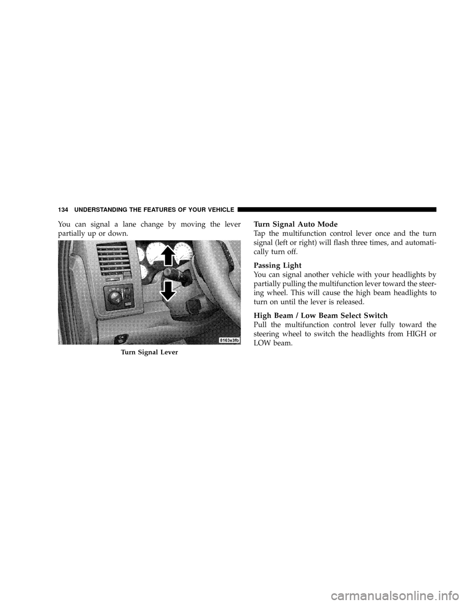
You can signal a lane change by moving the lever
partially up or down.Turn Signal Auto Mode
Tap the multifunction control lever once and the turn
signal (left or right) will flash three times, and automati-
cally turn off.
Passing Light
You can signal another vehicle with your headlights by
partially pulling the multifunction lever toward the steer-
ing wheel. This will cause the high beam headlights to
turn on until the lever is released.
High Beam / Low Beam Select Switch
Pull the multifunction control lever fully toward the
steering wheel to switch the headlights from HIGH or
LOW beam.
Turn Signal Lever
134 UNDERSTANDING THE FEATURES OF YOUR VEHICLE
Page 203 of 527
Two Types of Signals
There are two basic types of radio signals: AM or
Amplitude Modulation, in which the transmitted sound
causes the amplitude, or height, of the radio waves to
vary; and FM or Frequency Modulation, in which the
frequency of the wave is varied to carry the sound.
Electrical Disturbances
Radio waves may pick up electrical disturbances during
transmission. They mainly affect the wave amplitude,
and thus remain a part of the AM reception. They
interfere very little with the frequency variations that
carry the FM signal.
AM Reception
AM sound is based on wave amplitude, so AM reception
can be disrupted by such things as lightning, power lines
and neon signs.
FM Reception
Because FM transmission is based on frequency varia-
tions, interference that consists of amplitude variations
can be filtered out, leaving the reception relatively clear,
which is the major feature of FM radio.
NOTE:The radio, steering wheel radio controls (if
equipped), and 6-disc CD/DVD changer (if equipped)
will remain active for up to 10 minutes after the ignition
switch has been turned OFF. Opening a vehicle front
door will cancel this feature.
UNDERSTANDING YOUR INSTRUMENT PANEL 201
4
Page 248 of 527
REMOTE SOUND SYSTEM CONTROLS Ð IF
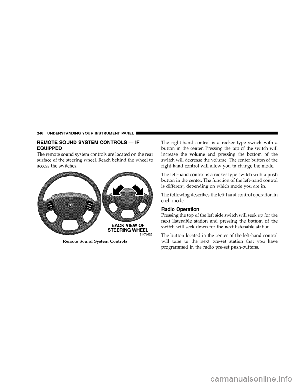
EQUIPPED
The remote sound system controls are located on the rear
surface of the steering wheel. Reach behind the wheel to
access the switches.The right-hand control is a rocker type switch with a
button in the center. Pressing the top of the switch will
increase the volume and pressing the bottom of the
switch will decrease the volume. The center button of the
right-hand control will allow you to change the mode.
The left-hand control is a rocker type switch with a push
button in the center. The function of the left-hand control
is different, depending on which mode you are in.
The following describes the left-hand control operation in
each mode.
Radio Operation
Pressing the top of the left side switch will seek up for the
next listenable station and pressing the bottom of the
switch will seek down for the next listenable station.
The button located in the center of the left-hand control
will tune to the next pre-set station that you have
programmed in the radio pre-set push-buttons.
Remote Sound System Controls
246 UNDERSTANDING YOUR INSTRUMENT PANEL
Page 334 of 527
WARNING!
²Do not use a tire, wheel size or rating other than that
specified for your vehicle. Some combinations of
unapproved tires and wheels may change suspension
dimensions and performance characteristics, result-
ing in changes to steering, handling, and braking of
your vehicle. This can cause unpredictable handling
and stress to steering and suspension components.
You could lose control and have an accident resulting
in serious injury or death. Use only the tire and
wheel sizes with load ratings approved for your
vehicle.
²Never use a tire with a smaller load index or capacity,
other than what was originally equipped on your
vehicle. Using a tire with a smaller load index could
result in tire overloading and failure. You could lose
control and have an accident.
²Failure to equip your vehicle with tires having ad-
equate speed capability can result in sudden tire
failure and loss of vehicle control.
CAUTION!
Replacing original tires with tires of a different size
may result in false speedometer and odometer
readings.
Alignment and Balance
Poor suspension alignment may result in:
²Fast tire wear.
²Uneven tire wear, such as feathering and one-sided
wear.
²Vehicle pull to right or left.
Tires may also cause the vehicle to pull to the left or right.
Alignment will not correct this condition. See your
authorized dealer for proper diagnosis.
332 STARTING AND OPERATING
Page 346 of 527
WARNING!
It is the driver 's responsibility to change to the max
load inflation pressure (cold) low pressure warning
threshold condition when not driving in the light
load condition as defined as two occupants ( 150 lbs
each) plus 200 pounds of cargo. The vehicle ªLight
Load Definitionº is found in the Supplemental Tire
Pressure Information label located on the rear face of
the driver door. Failure to do so may cause you to lose
control resulting in an accident, causing serious or
fatal injury.
To switch back to the max load inflation pressure (cold)
low pressure warning threshold, press the ªLight Loadº
reset switch. It is not necessary to first fill the tires to the
max load inflation pressure (cold) values to switch the
TPMS system to the max load inflation pressure (cold)low pressure warning threshold. If after pressing the
ªLight Loadº reset switch and tire pressures are below
the max load inflation pressure (cold) low pressure
warning thresholds, the TPMS low pressure warning
telltale lamp located in the Instrument Cluster will turn
ON and a chime will sound. The tire pressures are now
required to be inflated to the max load inflation pressure
(cold) values described on the Tire and Loading Informa-
tion label. The Tire and Loading Information label is
located on the drivers side B-pillar. If the ªLight Loadº
reset switch LED turns OFF the TPMS has been reset and
the TPMS is using the max load inflation pressure (cold)
low pressure warning thresholds.
Tire Pressure Monitor System Components
The Tire Pressure Monitor System (TPMS) uses wireless
technology with wheel rim mounted electronic sensors to
monitor tire pressure levels. Sensors, mounted to each
wheel as part of the valve stem, transmit tire pressure
readings to the Receiver Module.
344 STARTING AND OPERATING
Page 389 of 527
NOTE:The winch mechanism is designed for use with
the jack extension tube only. Use of an air wrench or other
power tools is not recommended and can damage the
winch.
Tire Changing Procedure
WARNING!
Getting under a jacked-up vehicle is dangerous. The
vehicle could slip off the jack and fall on you. You
could be crushed. Never get any part of your body
under a vehicle that is on a jack. Never start or run
the engine while the vehicle is on a jack. If you need
to get under a raised vehicle, take it to a service center
where it can be raised on a lift.Do not raise this vehicle using a bumper jack. The jack is
designed as a tool for changing tires on this vehicle only.
It is not recommended that the jack be used for service
purposes or to lift more than one wheel at a time.
Preparations
Park the vehicle on a firm level surface, avoiding ice or
slippery areas. Set the parking brake and place the gear
selector in PARK (automatic transmission) or REVERSE
(manual transmission). On four-wheel drive vehicles,
shift the transfer case to the ª4Lº position.
WARNING!
Do not attempt to change a tire on the side of the
vehicle close to moving traffic. Pull far enough off
the road to avoid the danger of being hit when
operating the jack or changing the wheel.
WHAT TO DO IN EMERGENCIES 387
6
Page 390 of 527
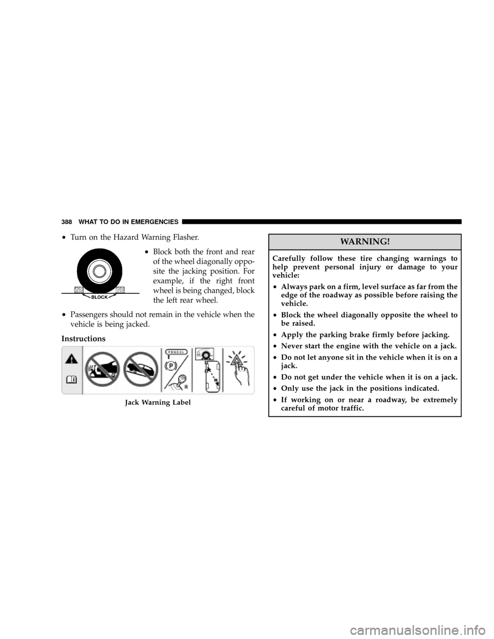
²Turn on the Hazard Warning Flasher.
²Block both the front and rear
of the wheel diagonally oppo-
site the jacking position. For
example, if the right front
wheel is being changed, block
the left rear wheel.
²Passengers should not remain in the vehicle when the
vehicle is being jacked.
Instructions
WARNING!
Carefully follow these tire changing warnings to
help prevent personal injury or damage to your
vehicle:
²Always park on a firm, level surface as far from the
edge of the roadway as possible before raising the
vehicle.
²Block the wheel diagonally opposite the wheel to
be raised.
²Apply the parking brake firmly before jacking.
²Never start the engine with the vehicle on a jack.
²Do not let anyone sit in the vehicle when it is on a
jack.
²Do not get under the vehicle when it is on a jack.
²Only use the jack in the positions indicated.
²If working on or near a roadway, be extremely
careful of motor traffic.
Jack Warning Label
388 WHAT TO DO IN EMERGENCIES
Page 452 of 527

Automatic Transmission Fluid and Filter Change
To obtain best performance and long life for automatic
transmissions, the manufacturer recommends that they
be given regular maintenance service by an authorized
dealer or Service Center. It is important that the trans-
mission fluid is maintained at the correct level, and that
it is drained and refilled as specified.
Use only manufacturer 's recommended transmission
fluid; for correct fluid type, refer to ªAutomatic Trans-
missionº under ªFluids, Lubricants and Genuine Partsº
in this section. It is important that the transmission fluid
be maintained at the prescribed level using the recom-
mended fluid..
The fluid and filter(s) should be changed as specified in
the Maintenance Schedule (Section 8).
NOTE:If the transmission is disassembled for any
reason, the fluid and filter should be changed.
Special Additives
Automatic Transmission Fluid (ATF) is an engineered
product and its performance may be impaired by supple-
mental additives. Therefore, do not add any fluid addi-
tives to the transmission. The only exception to this
policy is the use of special dyes to aid in detecting fluid
leaks. In addition, avoid using transmission sealers as
they may adversely affect seals.
Front Wheel Bearings
Front wheel bearings for your vehicle are sealed-for-life.
They do not require greasing or seal replacement. In
some instances, these bearings will ªpurgeº excess grease
and the bearing housing will look slightly wet. This is
normal.
²Periodic inspection for excess play is recommended.
²If a bearing assembly is accidentally separated when
servicing the brake rotors, it should be replaced.
450 MAINTAINING YOUR VEHICLE