Page 216 of 402

press the SEEK UP button until all 12 ESN/SID digits
display. The SEEK DOWN will page down until the first
four digits display. The radio will exit the ESN/SID mode
when any other button is pushed, the ignition is turned
OFF, or five minutes have passed since any button was
pushed.
ESN/SID Access with RAQ and RAK Radios
With the ignition switch in the ACC position and the
radio OFF, press the CD Eject and TIME buttons simul-
taneously for three seconds. All twelve ESN/SID num-
bers will display. The radio will exit the ESN/SID mode
when any other button is pushed, the ignition is turned
OFF, or five minutes have passed since any button was
pushed.
ESN/SID Access with REC Navigation Radios
Please refer to your Navigation User’s Manual.With the ignition in the ACC position and the radio off,
press the CD Eject and SET buttons simultaneously until
the 12 digits of the ESN/SID appear on the screen.
Selecting Satellite Mode in REF, RAQ, And RAK
Radios
Selecting Satellite Mode — REF Radio
Press the MODE button repeatedly until the word�SAT�
appears in the display.
A CD may remain in the radio while in the Satellite radio
mode.
Selecting Satellite Mode — RAQ and RAK Radio
Press the MODE button repeatedly until the word�SAT�
appears in the display.
These radios will also display the current station name
and program type. For more information, such as song
title and artist, press the MSG or INFO button.
214 UNDERSTANDING YOUR INSTRUMENT PANEL
Page 217 of 402

A CD or tape may remain in the radio while in the
Satellite radio mode.
Selecting A Channel
Press and release the SEEK or TUNE knob to search for
the next channel. Press the top of the button to search up
and the bottom of the button to search down. Holding the
TUNE button causes the radio to bypass channels until
the button is released.
Press and release the SCAN button (if equipped) to
automatically change channels every seven seconds. The
radio will pause on each channel for seven seconds
before moving on to the next channel. The word�SCAN�
will appear in the display between each channel change.
Press the SCAN button a second time to stop the search.
NOTE:Channels that may contain objectionable content
can be blocked. Contact Sirius Customer Care at 888-539-
7474 to discuss options for channel blocking or unblock-
ing. Please have your ESN/SID information available.
Storing And Selecting Preset Channels
In addition to the 12 AM and 12 FM preset stations, you
may also commit 12 satellite stations to pushbutton
memory. These satellite channel preset stations will not
erase any AM or FM preset memory stations. Follow the
memory preset procedures that apply to your radio.
Using The PTY (Program Type) Button — If
Equipped
Follow the PTY button instructions that apply to your
radio.
PTY Button SCAN
When the desired program type is obtained, press the
SCAN button within five seconds. The radio will play
seven seconds of the selected channel before moving to
the next channel of the selected program type. Press the
SCAN button a second time to stop the search.
NOTE:Pressing the SEEK or SCAN button, while
performing a music type scan, will change the channel by
UNDERSTANDING YOUR INSTRUMENT PANEL 215
4
Page 242 of 402
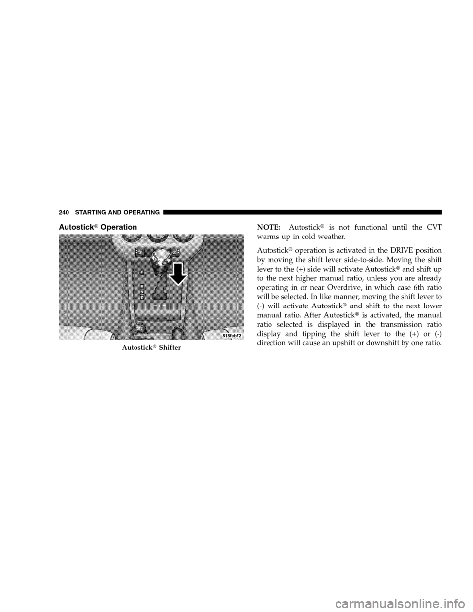
Autostick�OperationNOTE:Autostick�is not functional until the CVT
warms up in cold weather.
Autostick�operation is activated in the DRIVE position
by moving the shift lever side-to-side. Moving the shift
lever to the (+) side will activate Autostick�and shift up
to the next higher manual ratio, unless you are already
operating in or near Overdrive, in which case 6th ratio
will be selected. In like manner, moving the shift lever to
(-) will activate Autostick�and shift to the next lower
manual ratio. After Autostick�is activated, the manual
ratio selected is displayed in the transmission ratio
display and tipping the shift lever to the (+) or (-)
direction will cause an upshift or downshift by one ratio.
Autostick�Shifter
240 STARTING AND OPERATING
Page 278 of 402

NOTE:It is particularly important for you to check the
tire pressure in all of your tires regularly and to maintain
the proper pressure.
The TPMS consists of the following components:
•Receiver Module
•Four Tire Pressure Monitoring Sensors
•Three Trigger Modules (mounted in three of the four
wheel wells)
•Various Tire Pressure Monitoring System Messages,
which display in the Electronic Vehicle Information
Center (EVIC)
•Yellow Tire Pressure Monitoring Telltale Light
Tire Pressure Monitoring Low Pressure Warnings
The Tire Pressure Monitoring Telltale Light will illumi-
nate in the instrument cluster and an audible chime will
be activated when one or more of the four active road tirepressures are low. The audible chime will sound once
every ignition cycle for each condition that it detects. In
addition, the EVIC will display a graphic of the pressure
value(s) with the low tire(s) flashing.
Should a low tire condition occur on any of the four
active road tire(s), you should stop as soon as possibleLow Tire Pressure Display
276 STARTING AND OPERATING
Page 279 of 402
 that is flashing on the graphic
display to the vehicle’s recommended cold placard pres-
sure value. The system will automatically update, the
graphic display of the press")
and inflate the low tire(s) that is flashing on the graphic
display to the vehicle’s recommended cold placard pres-
sure value. The system will automatically update, the
graphic display of the pressure value(s) will stop flash-
ing, and the Tire Pressure Monitoring Light will extin-
guish once the updated tire pressure(s) have been re-
ceived. The vehicle may need to be driven for up to 10
minutes above 15 mph (25 km/h) to receive this infor-
mation.
Check TPMS Message
The Tire Pressure Monitoring Telltale Light will flash on
and off for 75 seconds, and remain on solid when a
system fault is detected. The system fault will also sound
a chime. The EVIC will display a “CHECK TPM SYS-
TEM” message for three seconds. This text message is
then followed by a graphic display, with “- -“ in place of
the pressure value(s) indicating which Tire Pressure
Monitoring Sensor(s) is not being received.If the ignition key is cycled, this sequence will repeat,
providing the system fault still exists. If the system fault
no longer exists, the Tire Pressure Monitoring Telltale
Light will no longer flash, the�CHECK TPM SYSTEM�
text message will not be present, and a pressure value
Check TPM System Display
STARTING AND OPERATING 277
5
Page 280 of 402

will be displayed instead of dashes. A system fault can
occur with any of the following scenarios:
1. Jamming due to electronic devices or driving next to
facilities emitting the same radio frequencies as the TPM
sensors.
2. Installing some form of aftermarket window tinting
that affects radio wave signals.
3. Snow or ice around the wheels or wheel housings.
4. Using tire chains on the vehicle.
5. Using wheels/tires not equipped with TPM sensors.
NOTE:Your vehicle is equipped with a compact spare
wheel and tire assembly.
1. The compact spare tire does not have a tire pressure
monitoring sensor. Therefore, the TPMS will not monitor
the tire pressure in the compact spare tire.2. If you install the compact spare tire in place of a road
tire that has a pressure below the low-pressure warning
limit, upon the next ignition key cycle, a chime will
sound and the Tire Pressure Monitoring Telltale Light
will still turn ON due to the low tire.
3. However, after driving the vehicle for up to 10 min-
utes above 15 mph (25 km/h), the Tire Pressure Moni-
toring Telltale Light will flash on and off for 75 seconds
and then remain on solid.
4. For each subsequent ignition key cycle, a chime will
sound and the Tire Pressure Monitoring Telltale Light
will flash on and off for 75 seconds and then remain on
solid.
5. Once you repair or replace the original road tire and
reinstall it on the vehicle in place of the compact spare
tire, the TPMS will update automatically and the Tire
Pressure Monitoring Telltale Light will turn OFF, as long
as no tire pressure is below the low-pressure warning
278 STARTING AND OPERATING
Page 288 of 402

NOTE:Tighten the gas cap about one-quarter turn until
you hear one click. This is an indication that cap is
properly tightened.
If the gas cap is not tightened properly, the MIL will come
on. Be sure that the gas cap is tightened every time the
vehicle is refueled.
WARNING!
A fire may result if gasoline is pumped into a
portable container that is inside of a vehicle. You
could be burned. Always place gas containers on the
ground while filling.
Loose Fuel Filler Cap Message
If the vehicle diagnostic system determines that the fuel
filler cap is loose or improperly installed, a “gASCAP”
message will be displayed in the Odometer/Trip Odom-
eter in the instrument cluster. Refer to “Instrument
Cluster Description” in Section 4 of this manual. Tighten
the fuel filler cap properly and press the Odometer/Trip
Odometer reset button to turn the message off. If the
problem continues, the message will appear the next time
the vehicle is started. Refer to “Onboard Diagnostic
System — OBDII” in Section 7 of this manual for more
information.
CAUTION!
Damage to the fuel system or emission control sys-
tem could result from using an improper fuel tank
filler cap (gas cap). A poorly fitting cap could let
impurities into the fuel system.
286 STARTING AND OPERATING