Page 173 of 494
PREMIUM INSTRUMENT CLUSTER
UNDERSTANDING YOUR INSTRUMENT PANEL 171
4
Page 174 of 494

INSTRUMENT CLUSTER DESCRIPTIONS
1. Fuel Gauge
When the ignition switch is in the ON position, the
pointer will show the level of fuel remaining in the
fuel tank.
2. Fuel Door Reminder
This is a reminder that the Fuel Filler Door is
located on the left side of the vehicle.
3. Temperature Gauge
The temperature gauge shows engine coolant tem-
perature. Any reading below the red area of the
gauge shows that the engine cooling system is
operating properly. The gauge pointer may show a
higher than normal temperature when driving in hot
weather, up mountain grades, in heavy stop and go
traffic, or when towing a trailer.If the pointer rises to theH(red) mark, the instrument
cluster will sound a chime. Pull over and stop the vehicle.
Idle the vehicle with the air conditioner turned off until
the pointer drops back into the normal range. If the
pointer remains on theH(red) mark, turn the engine off
immediately and call for service.
There are steps that you can take to slow down an
impending overheat condition. If your air conditioning is
on, turn it off. The air conditioning system adds heat to
the engine cooling system and turning off the A/C
removes this heat. You can also turn the Temperature
control to maximum heat, the Mode control to Floor and
the Fan control to High. This allows the heater core to act
as a supplement to the radiator and aids in removing heat
from the engine cooling system.
4. Speedometer
Indicates vehicle speed.
172 UNDERSTANDING YOUR INSTRUMENT PANEL
Page 177 of 494

The two trip odometers show individual trip mileage. To
switch from odometer to trip odometers, press and
release the Trip Odometer button. To reset a trip odom-
eter, display the desired trip odometer to be reset then
push and hold the button until the display resets (ap-
proximately two seconds). Refer to “Trip Odometer But-
ton” for additional information.
Vehicle Warning Messages
When the appropriate conditions exist, “DOOR AJAR,”
“TRUNK AJAR,” or “gASCAP” will display in the odom-
eter.
NOTE:If the instrument cluster is equipped with the
optional Electronic Vehicle Information Center (EVIC),
then all warnings including “DOOR AJAR” and
“TRUNK AJAR” will only display in the EVIC. (Refer to
“Electronic Vehicle Information Center (EVIC)” in this
section for specific messages).gASCAP
If the vehicle diagnostic system detects a leak or change
in the evaporative system, or the fuel filler cap is loose,
improperly installed, or damaged, the words “gASCAP”
will display in the odometer. If this occurs, tighten the
fuel filler cap properly and press the odometer reset
button to turn off the “gASCAP” message. (Refer to
“Onboard Diagnostic System — OBDII” in Section 7 of
this manual for more information). If the problem con-
tinues, the message will appear the next time the vehicle
is started. See your authorized dealer service center as
soon as possible.
Change Oil
Your vehicle is equipped with an engine oil change
indicator system. The “Change Oil” message will flash in
the instrument cluster odometer for approximately 12
seconds after a single chime has sounded to indicate the
next scheduled oil change interval. The engine oil change
UNDERSTANDING YOUR INSTRUMENT PANEL 175
4
Page 178 of 494

indicator system is duty cycle based, which means the
engine oil change interval may fluctuate dependent upon
your personal driving style.
Unless reset, this message will continue to display each
time you turn the ignition switch to the ON position. To
turn off the message temporarily, press and release the
Trip Odometer button on the instrument cluster. To reset
the oil change indicator system (after performing the
scheduled maintenance) perform the following proce-
dure:
1. Turn the ignition switch to the ON position (Do not
start the engine).
2. Fully depress the accelerator pedal slowly three
times within 10 seconds.
3. Turn the ignition switch to the LOCK position.NOTE:If the indicator message illuminates when you
start the vehicle, the oil change indicator system did not
reset. If necessary repeat this procedure.
15. Cruise Indicator — If Equipped
This indicator shows that the Speed Control
System is ON.
16. Odometer/Trip Odometer Reset Knob
Single Trip Odometer
Press and release this button to change the display from
odometer to trip odometer. The word “Trip” displays to
show that the odometer is in Trip Mode. Press and release
the button again to change the display back to the
odometer.
To reset the trip odometer, first set the display to Trip
Mode. Then push and hold the button (approximately
two seconds) until the display resets to 0. The odometer
must be in Trip Mode to reset the trip odometer.
176 UNDERSTANDING YOUR INSTRUMENT PANEL
Page 184 of 494
” in Section 5 of this manual for more informa-
tion).
25. Malfuncti")
(Refer to “Tire Inflation Pressures” under “Tires — Gen-
eral Information” and to “Tire Pressure Monitor System
(TPMS)” in Section 5 of this manual for more informa-
tion).
25. Malfunction Indicator Light
This light is part of an onboard diagnostic system
called OBD that monitors emissions, engine, and
automatic transaxle control systems. The light
will illuminate when the key is in the ON/RUN position
before engine start. If the bulb does not come on when
turning the key from LOCK/OFF to ON/RUN, have the
condition checked promptly.
Certain conditions such as a loose or missing gas cap,
poor fuel quality, etc. may illuminate the light after
engine start. The vehicle should be serviced if the light
stays on through several of your typical driving cycles. In
most situations the vehicle will drive normally and will
not require towing.If the Malfunction Indicator Light flashes when the
engine is running, serious conditions may exist that
could lead to immediate loss of power or severe catalytic
converter damage. The vehicle should be serviced as
soon as possible if this occurs.
26. High Beam Indicator
This light shows that the headlights are on high
beam. Push the turn signal lever away from the
steering wheel to switch the headlights from high or low
beam.
27. Electronic Vehicle Information Center (EVIC)
Display—Premium Cluster Only
This display shows the EVIC messages when the appro-
priate conditions exist. Refer to “Electronic Vehicle Infor-
mation Center (EVIC)” in this section for more informa-
tion.
182 UNDERSTANDING YOUR INSTRUMENT PANEL
Page 185 of 494
ELECTRONIC VEHICLE INFORMATION CENTER
(EVIC) – IF EQUIPPEDThe Electronic Vehicle Information Center (EVIC) fea-
tures a driver-interactive display. It is located in the lower
left part of the cluster below the fuel and engine tem-
perature gauges. The EVIC consists of the following:
•System status
•Vehicle information warning message displays
•Personal settings (customer programmable features)
•Compass heading display (N, S, E, W, NE, NW, SE,
SW)
•Outside temperature display (°F or °C)
•Trip computer functions
•Audio mode displays – 12 preset Radio Stations or CD
Title and Track number when playing
•Tire Pressure Monitor System (TPMS) displays (if
equipped)
EVIC Display Location
UNDERSTANDING YOUR INSTRUMENT PANEL 183
4
Page 278 of 494
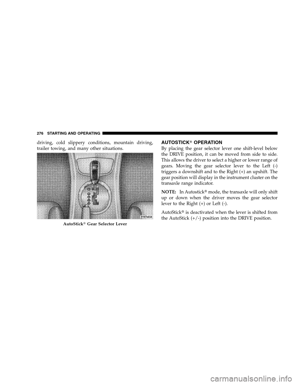
driving, cold slippery conditions, mountain driving,
trailer towing, and many other situations.AUTOSTICK�OPERATION
By placing the gear selector lever one shift-level below
the DRIVE position, it can be moved from side to side.
This allows the driver to select a higher or lower range of
gears. Moving the gear selector lever to the Left (-)
triggers a downshift and to the Right (+) an upshift. The
gear position will display in the instrument cluster on the
transaxle range indicator.
NOTE:In Autostick�mode, the transaxle will only shift
up or down when the driver moves the gear selector
lever to the Right (+) or Left (-).
AutoStick�is deactivated when the lever is shifted from
the AutoStick (+/-) position into the DRIVE position.
AutoStick�Gear Selector Lever
276 STARTING AND OPERATING
Page 279 of 494

AutoStick�General Information
•
You can start out in first or second gear. The system
will ignore attempts to upshift at too low of a vehicle
speed.
•If a ratio other than 1st is selected, and the vehicle is
brought to a stop, the transaxle control logic will
automatically select the 1st gear ratio.
•Starting out in second gear is helpful in snowy or icy
conditions.
•Avoid using speed control when Autostick�is en-
gaged.
•The transaxle will automatically shift up when maxi-
mum engine speed is reached while Autostick�is
engaged.
•Transaxle shifting will be more noticeable when
Autostick�is engaged.
•If a downshift would cause the engine to over-speed,
that shift will not occur until it is safe for the engine.
Mostly the transaxle will stay in the manually selected
ratio, however.
•If the system detects powertrain overheating, the
transaxle will revert to the automatic shift mode and
remain in that mode until the powertrain cools off.
•If the system detects a problem, it will disable the
AutoStick�mode and the transaxle will return to the
automatic mode until the problem is corrected.
PARKING BRAKE
When the parking brake is applied with the
ignition on, the Brake Light in the instrument
cluster will come on.
NOTE:This light, when illuminated with parking brake
application, shows only that the parking brake is on. It
does not show the degree of brake application.
STARTING AND OPERATING 277
5

 – IF EQUIPPEDThe Electronic Vehicle Information Center (EVIC) fea-
tures a driver-interactive display. It is located in the lower
left part of the cluste")