2008 CHRYSLER PACIFICA change wheel
[x] Cancel search: change wheelPage 193 of 457

2. Fully depress the accelerator pedal slowly three
times within 10 seconds.
3. Turn the ignition switch to the LOCK position.
NOTE:If the indicator message illuminates when you
start the vehicle, the oil change indicator system did not
reset. If necessary repeat this procedure.
14. Cruise Indicator
This indicator shows that the Speed Control
System is ON.
15. Malfunction Indicator Light
This light is part of an onboard diagnostic system
called OBD that monitors engine and automatic
transmission control systems. The light will illu-
minate when the key is in the ON position before engine
start. If the bulb does not come on when turning the key
from OFF to ON, have the condition checked promptly.Certain conditions such as a loose or missing gas cap,
poor fuel quality, etc. may illuminate the light after
engine start. The vehicle should be serviced if the light
stays on through several of your typical driving cycles. In
most situations the vehicle will drive normally and will
not require towing.
The Malfunction Indicator Light flashes to alert you to
serious conditions that could lead to immediate loss of
power or severe catalytic converter damage. The vehicle
should be serviced as soon as possible if this occurs.
16. High Beam Light
This light shows that the headlights are on high
beam. Pull the Multi-Function lever towards the
steering wheel to switch the headlights from high or low
beam.
UNDERSTANDING YOUR INSTRUMENT PANEL 193
4
Page 211 of 457

you understand and save you concern about these ªap-
parentº malfunctions, you must understand a point or
two about the transmission and reception of radio sig-
nals.
Two Types of Signals
There are two basic types of radio signals... AM or
Amplitude Modulation, in which the transmitted sound
causes the amplitude, or height, of the radio waves to
vary... and FM or Frequency Modulation, in which the
frequency of the wave is varied to carry the sound.
Electrical Disturbances
Radio waves may pick up electrical disturbances during
transmission. They mainly affect the wave amplitude,
and thus remain a part of the AM reception. They
interfere very little with the frequency variations that
carry the FM signal.
AM Reception
AM sound is based on wave amplitude, so AM reception
can be disrupted by such things as lightning, power lines
and neon signs.
FM Reception
Because FM transmission is based on frequency varia-
tions, interference that consists of amplitude variations
can be filtered out, leaving the reception relatively clear,
which is the major feature of FM radio.
NOTE:The radio, steering wheel radio controls (if
equipped), and 6 disc CD/DVD changer (if equipped)
will remain active for up to 90 seconds after the ignition
switch has been turned off, depending upon the acces-
sory delay setting. Opening a vehicle front door will
cancel this feature.
UNDERSTANDING YOUR INSTRUMENT PANEL 211
4
Page 249 of 457

REMOTE SOUND SYSTEM CONTROLS
The remote sound system controls are located on the rear
surface of the steering wheel at the 3 and 9 o'clock
positions.
The right hand rocker switch has a push button in the
center and controls the volume and mode of the sound
system. Pressing the top of the rocker switch will increase
the volume and pressing the bottom of the rocker switch
will decrease the volume. Pressing the center button
changes the operation of the radio from AM to FM to
Tape or CD mode depending on which radio is in the
vehicle.
The left hand rocker switch has a push button in the
center. The function of the left hand switch is different
depending on which mode you are in.
The following describes the left hand rocker switch
operation in each mode:
Radio Operation
Pressing the top of the switch will SEEK up for the next
listenable station and pressing the bottom of the switch
will SEEK down for the next listenable station.
The button located in the center of the left hand switch
will tune to the next pre-set station that you have
programmed in the radio pre-set push-button.
CD Player
Pressing the top of the switch once will go to the next
track on the CD. Pressing the bottom of the switch once
will go to the beginning of the current track or to the
beginning of the previous track if it is within one second
after the current track begins to play.
If you press the switch up or down twice it plays the
second track, three times, it will play the third, etc.
The button in the center of the left hand switch has no
function in this mode.
UNDERSTANDING YOUR INSTRUMENT PANEL 249
4
Page 311 of 457

WARNING!
²Do not use a tire, wheel size or rating other than
that specified for your vehicle. Some combina-
tions of unapproved tires and wheels may change
suspension dimensions and performance charac-
teristics, resulting in changes to steering, han-
dling, and braking of your vehicle. This can cause
unpredictable handling and stress to steering and
suspension components. You could lose control
and have an accident resulting in serious injury
or death. Use only the tire and wheel sizes with
load ratings approved for your vehicle.
²Never use a tire with a smaller load index or
capacity, other than what was originally equipped
on your vehicle. Using a tire with a smaller load
index could result in tire overloading and failure.
You could lose control and have an accident.
²Failure to equip your vehicle with tires having
adequate speed capability can result in sudden
tire failure and loss of vehicle control.
CAUTION!
Replacing original tires with tires of a different size
may result in false speedometer and odometer
readings.
Alignment And Balance
Poor suspension alignment may result in:
²Fast tire wear.
²Uneven tire wear, such as feathering and one-sided
wear.
²Vehicle pull to right or left.
Tires may also cause the vehicle to pull to the left or right.
Alignment will not correct this condition. See your dealer
for proper diagnosis.
STARTING AND OPERATING 311
5
Page 317 of 457

²The TPMS is not a substitute for proper tire mainte-
nance, and it is the driver's responsibility to maintain
correct tire pressure, using an accurate tire pressure
gage, even if under-inflation has not reached the level
to trigger illumination of the TPMS Telltale Lamp.
²Seasonal temperature changes will affect tire pressure,
and the TPMS will monitor the actual tire pressure in
the tire.
Basic TPMS without EVIC Ð If Equipped
The TPMS uses wireless technology with wheel rim
mounted electronic sensors to monitor tire pressure lev-
els. Sensors, mounted to each wheel as part of the valve
stem, transmit tire pressure readings to the Receiver
Module.
NOTE:It is particularly important, for you to check the
tire pressure in all of your tires regularly and too main-
tain the proper pressure.The Basic TPMS consists of the following components:
²Receiver Module
²4 Tire Pressure Monitoring Sensors
²Tire Pressure Monitoring Telltale Lamp
The Tire Pressure Monitoring Telltale Lamp
will illuminate in the instrument cluster and an
audible chime will be activated when one or
more of the four active road tire pressures are
low. Should this occur you should stop as soon as
possible, check the inflation pressure of each tire on your
vehicle, and inflate each tire to the manufacturer recom-
mended pressure, located on the tire pressure placard.
The system will automatically update and the TPMS
warning light will extinguish once the updated tire
pressure(s) have been received.
STARTING AND OPERATING 317
5
Page 355 of 457

CAUTION!
The winch mechanism is designed for use with the
jack handle only. Use of an air wrench or other power
tools is not recommended and can damage the winch.
When the spare is clear, tilt the retainer at the end of the
cable and pull it through the center of the wheel.
Preparations For Jacking
Park the vehicle on a firm level surface, avoid ice or
slippery areas,set the parking brakeand place the gear
selector in PARK. Turn OFF the ignition.
WARNING!
Do not attempt to change a tire on the side of the
vehicle close to moving traffic. Pull far enough off
the road to avoid the danger of being hit when
operating the jack or changing the wheel.
²Turn on the Hazard Warning Flasher.
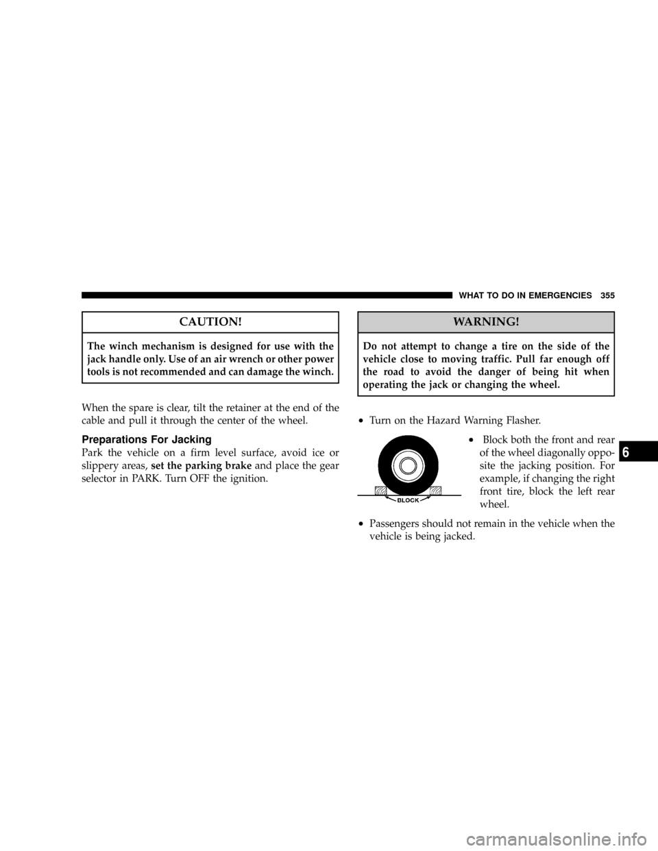
²Block both the front and rear
of the wheel diagonally oppo-
site the jacking position. For
example, if changing the right
front tire, block the left rear
wheel.
²Passengers should not remain in the vehicle when the
vehicle is being jacked.
WHAT TO DO IN EMERGENCIES 355
6
Page 357 of 457

1. Remove the spare wheel, scissors jack and jack-handle
from stowage.
2. Carefully pry off the wheel center cap if equipped,
using the tip of the jack handle.
3. Loosen (but do not remove) the wheel lug nuts by
turning them to the left one turn while the wheel is still
on the ground.
NOTE:Do not oil wheel studs. For chrome wheels, do
not substitute with chrome plated wheel nuts.
4. There are two jack engagement locations on each side
of the body Ð refer to the following illustration.
5. These locations are on the sill flange on the underside
of the body. The jack is to be located, engaging the
flanges, 20 cm (8 inches) inward from the edge of the
wheel opening closest to the wheel to be changed. Place
the wrench on the jack screw and turn to the right until
the jack head is properly engaged in the described
Jack Engagement Locations
WHAT TO DO IN EMERGENCIES 357
6
Page 360 of 457

NOTE:When reinstalling the wheel center cap, insure
that the valve stem symbol on the back of the cap is
pointed toward the wheel valve stem. Install the center
cap using hand pressure only. Do not use a hammer.
Wheel Nuts
All wheel nuts should be tightened occasionally to elimi-
nate the possibility of wheel studs being sheared or the
bolt holes in the wheels becoming elongated. This is
especially important during the first few hundred miles
of operation, and after each time a tire is changed, to
allow the wheel nuts to become properly set. All nuts
should first be firmly seated against the wheel. The nuts
should then be tightened to recommended torque.
Tighten the nuts to final torque in increments. Progress
around the bolt circle, tightening the nut opposite to the
nut just previously tightened until final torque is
achieved. Recommended torque is 130 N´m (95 ft. lbs).
JUMP-STARTING PROCEDURE
WARNING!
²Do not attempt to push or tow your vehicle to get it started.
Vehicles equipped with an automatic transmission cannot
be started this way. Unburned fuel could enter the catalytic
converter and once the engine has started, ignite and
damage the converter and vehicle. If the vehicle has a
discharged battery, booster cables may be used to obtain a
start from another vehicle. This type of start can be danger-
ous if done improperly, so follow this procedure carefully.
²Battery fluid is a corrosive acid solution; do not allow
battery fluid to contact eyes, skin or clothing. Don't lean
over battery when attaching clamps or allow the clamps to
touch each other. If acid splashes in eyes or on skin, flush
contaminated area immediately with large quantities of
water.
²A battery generates hydrogen gas which is flammable and
explosive. Keep flame or spark away from the vent holes.
Do not use a booster battery or any other booster source
with an output that exceeds 12 volts.
²Take care to avoid the radiator cooling fan whenever the
hood is raised. It can start anytime the ignition switch is on.
You can be hurt by the fan.
360 WHAT TO DO IN EMERGENCIES