2008 AUDI TT ROADSTER reset
[x] Cancel search: resetPage 41 of 316
To del ete maximum sp eed
-Turn off the ignition.
- Briefly press the button in the instrument cluste r
=>
page 38, fig . 24. The odometer and the digital clock are
now illuminated.
- Press the button for at leas t 2 seconds. T he curren tly
stored maximum speed appears in the display.
Press the rese t button in the w ipe r lever ®=>
page 38,
fig. 25 until the crossed out speed warni ng symbol fo r
warning threshold 2 appears in the d isplay.
A few seconds after the adjustment is comp leted, the illumination
for the odometer and the digital clock wi ll go out .
[ i J Tip s
This warning threshold can a lso be controlled through the trip
computer ~
page 28, "Navigating the menu". •
Contro ls and eq uip
ment
Dri ver in form ati on syst em
Trip computer
Introduction
The trip computer gives you inf ormation on current and
average fuel mileage, average speed, fuel range and
driving time .
Fig . 2 6 Trip c omput er
di sp lay: Ave ra g e f uel
mi lea ge
You can switch between the trip computer 1 and 2 by pressing the
Reset button
@ ~ page 40 , fig. 27
You can tell which memory level is currently active by the number in
the display ~ fig . 26 . The data from the single -trip memory
(memory level 1) is being disp layed if a
1 appears in the display. If a
2 is shown, then the data from the total -trip memory is being
displayed (memory leve l 2) .
Sin gle -trip mem ory (Trip compute r 1)
The single -t r ip memory stores the trip information from the time the
ignition is turned on until it is turned off. If the trip is continued
within 2 hour s from the time the ignition was turned off, the new
data wi ll be included in the calcu lation of the current trip informa
tion. If the trip is interrup ted for
more than 2 hour s the memory is
reset automatica lly. _,.
Vehicle care I I irechnical data
Page 42 of 316
Driver inf ormation sy ste m
To ta l-tr ip mem ory ( Trip compu te r 2)
Unlike the single -trip memory, the total -tr ip memory is not reset
automatically . This permits you to evaluate your driving data for the
entire period between manua l resets.
Fu el r an ge
The estimated cruising range in miles (km) appears in the display.
This tells you how far your vehicle will be able to travel on the
current tank of fuel and with the same driving sty le . The display
changes in increments of 6 miles (10 km).
The cruising range is calculated based on the fuel consumption for
t he last 18 miles (30 km). If you drive conservatively, the cruising
range will increase .
Average fuel m ile ag e
The average fuel economy in MPG (1/100 km) since you last cleared
the memory appears in this display. You can use this display to
adjust your driving technique to achieve a desired mileage.
C ur rent fuel mil eage
The instantaneous fuel consumption in mi les per gallon (1/100 km)
is shown in th is d isplay. You can use this display to adjust your
driving technique to achieve a desired mileage.
Fue l consumption is recalcu la ted at intervals of 33 yards (30
meters). When the vehicle is stationary, the most recent fuel
consumption is d isplayed .
Average speed
The average speed in mph (km/h) s ince the last time the display was
reset appears in the display .
Elap se d time
The length of time that you have been driving since you last reset
the memory appears in this display.
Di stance
The elapsed distance since the last time the memory was cleared
appears in the display. The maximum distance that can be recorded
is 9,999 .9 miles (9,999 .9 kilometers).
[ i ] Tips
• Fuel consumptions (average and current), range and speed are
displayed in metric units on Canadian models.
• All stored values will be lost if the vehicle battery is
disconnected .•
Operation
The trip computer is controlled by two switches on the
windshield wiper lever.
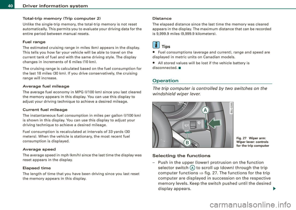
S ele cting th e fun ctions
Fig. 27 Wiper ar m:
W iper l ever: co ntrols
fo r th e tr ip com pute r
P u sh in the upper (lower) pro trusion o n the function
se lector switch @to scroll up (dow n) through the trip
computer functions~ fig. 27. The functions for the trip
comp uter are displayed in succession on the respect ive
memory leve ls. Keep the switc h pus hed until the desired
display appears . .-,,
Page 43 of 316
Switchin g bet w ee n m enu l ev els
- Tap the Rest button ® briefly to reach the various menu
levels one after the other ("Computer 1 ", "Computer 2",
"Navigation system"* and "Start menu") .
Rese ttin g th e fun ction to z ero
- Select the desired function.
- Push the reset button ® for at least two seco nds .
The trip computer only operates when the ignition is on. When you
turn on the ignition, the function that was in use when you last
turned the ignition off will be displayed .
In addition to the trip computer information (memory level 1 or 2)
and navigation information can be displayed. To switch the display
between the different systems, tap the Reset button
@ briefly .
You can reset the following va lues to zero using the reset button:
• driving time
• average mileage
• average speed
In addition,
a ll the values in the single -trip or the total-trip memory
can be de leted simu ltaneously .
[ i ] Tips
• If you hold down the reset button for longer than 2 seconds, the
current value (for example, average fuel consumption) will be reset
to zero .
• Malfunction displays in Auto -Check Control are shown even with
the display switched off.
• All stored values will be lost if the vehicle battery is
disconnected. •
Controls and equip
ment
Dri ver infor mat io n sy ste m
Tire pressure monitoring system
General notes
As an added safety feature, your vehicle has been equipped with a
tire pressure monitoring system (TPMS) that illuminates a low tire
pressure telltale when one or more of your tires is significant ly
under -inflated. The TPMS only provides a low tire pressure warning
and does not reinflate your tires.
Accordingly, when the low tire pressure tellta le illuminates, you
should stop and check your tires as soon as possib le, and inflate
them to the proper pressure. Driving on a significantly under
inflated t ire causes the tire to overheat and can lead to tire failure .
Under -inflation a lso reduces fuel efficiency and tire tread l ife, and
may affect the vehicle's handling and stopping ability.
(D Note
• Please note that the TPMS is not a substitute for proper tire
maintenance, and it is the driver's respons ib ility to maintain correct
tire pressure, even if under -inflation has not reached the level to
trigger illumination of the TPMS low tire pressure telltale .
• Each tire, including the spare, should be checked monthly when
cold and inflated to the inflat ion pressure recommended by the
vehic le manufacturer on the vehicle p lacard or tire inflation pres
s u re label. (If your vehicle has tires of a different size than the size
indicated on the vehicle placard or tire inflation pressure labe l, you
should determine the proper tire inflation pressure for those
tires.) •
TPMS malfunction indicator
Your vehic le has a lso been equipped with a TPMS malfunction indi
cator to indicate when the system is not operating proper ly . The
TPMS malfunction indicator is combined with the low tire pressure _.,
I • •
Page 54 of 316
Openin g a nd clo sin g
PANIC B utton
- Push the red button@to activate the panic function. The
horn sounds and the turn signals flash.
- Push the button ® again to deactivate the panic func-
tion.
The remote controls allows you to:
• lock or unlock the vehicle
• selectively unlock the rear lid.
The turn signals wi ll flash briefly whenever you lock or unlock the
vehic le. Also, the interior light will come on or go off whenever you
open or close the driver's door.
The transmitter and battery are located in the head of the remote control. The receiver is located inside the vehicle. The maximum
effective range depends on several things. Remember, if the battery
is weak, the effective range decreases.
The remote -contro l key contains a fo ld -out key that you can use to
manually lock or unlock the vehicle and to start the engine.
If you need to replace the remote contro l, or if you need to have it
repaired, you must see your authorized Audi dealer . On ly then can
you use the key again.
& WARNING
Re ad and follo w all WARNINGS ~ & in "General de scr iption " on
page 50 .
[ i J Tips
• The remote control key is automatically deactivated when the
ignition is switched on.
• The operation of the remote control key can be temporarily
disrupted by interference from transmitters in the vicinity of the vehic
le working in the same frequency range (e.g . a cell phone,
radio equipment).
• In order to make sure the locking function is working, you should
a lways keep your eye on the vehic le to make sure it is properly
locked .
• Do not use the remote control if you are inside the ca r, otherwise
you may unintentionally lock the vehicle, and then you would set off
the an ti-theft alarm when you try to start the engine or open a door.
I n case this happens anyhow, push the unlock button@.
• Use the panic func tion only if you are in an emergency
situation. •
Resetting the remote control
The remote con tr o l must be reset if the vehicle does not
unlock.
- Press the unlock
III button on the remote control.
- Unlock or lock the vehicle once at t he door lock using the
stem of the remote control key.
T he synchronization process must not take longer than 30
seco nds. •
Page 113 of 316
On the road -
----------------
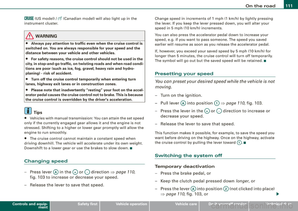
CRUISE (US mod ell/ f-f (Canadian mod ell will a lso light up in the
instrument cluster .
& WARNING
• Always pay att enti on to traffic ev en whe n the c rui se control is
swi tched o n. Yo u are alway s resp onsi ble for your spe ed and the
di stanc e betw een your veh icle and other ve hic le s.
• Fo r sa fet y re as on s, th e c ruise control shou ld not be u sed in the
c it y, in stop -and -go traffic , on twi sting road s and when road condi
t ion s a re poor (such as ice, fog, gra vel, hea vy ra in and hydro
planing ) - risk of accid ent.
• Turn off the cr uis e control t empor arily when e nte ring turn
lane s, highwa y ex it lane s or in con stru ctio n z one s.
• Please note that inad vertentl y "re sting " your foot on the a ccel
er ato r ped al ca use s t he crui se control not to br ake . Thi s is because
the cru ise control i s overridden b y the dri ve r's acc eleration .
[ i] Tip s
• Vehicles w ith manua l transmission : You can at tain the set speed
only if the currently engaged gear allows it and the engine is not
stressed. Shifting to a higher or lower gear promptly will allow the
engine to run smooth ly .
• The cruise control cannot maintain a constant speed when
driving downhi ll. The vehicle will acce lerate under its own weight .
Downshift to a lower gear or use the brakes to s low down. •
Changing speed
-Press lever © in the 0 or O direction ~ page 110,
fig. 103 to increase or dec rease your speed.
- Release the lever to save that speed .
Controls and equip
ment
Change speed in increments of 1 mph (1 km/h) by lightly pressing
the lever . If you keep the lever pressed down, you will a lter your
speed in 5 mph (10 km /h) increments .
You can a lso press the acce lerator pedal down to increase your
speed, e.g. if you want to pass someone. The speed you saved
earlier will resume as soon as you release the accelerator pedal.
I f , however, you exceed your saved speed by 5 mph (10 km/h) for
longer than 5 minutes, the cruise control will turn off temporarily .
The symbol will go ou t but the saved speed will be retained. •
Presetting your sp eed
You can preset your desired speed while the vehicle is not
moving.
Turn on the ignition.
P ull lever @into position
0 ~ page 110, fig. 103.
Press the lever in the
0 or O direction to increase or
decrease your speed.
- Release the lever to save that speed .
This function makes it possible, for example, to save the speed you
want before driving on the highway . Once on the highway, activate
the cruise contro l by pulling the lever toward
(D . •
Switching the system off
Tempor ary d ea ctiv ati o n
Press the brake pedal, or
- Keep the c lutch pedal pressed down
longer, or
- Press t he lever © into positio n
0 (n ot c licked i nto pla ce)
~ page 110 , fig. 1 03 , or ~
I • •
Page 276 of 316

llffl.,___F_ u_ s_ e_s _ a_n _ d_ b_ u_lb _ s _______________________________________________ _
The various electrical circuits are protected by fuses . The fuses are
clustered in a central ized unit. The unit is located behind the face
panel at the end of the instrument panel.
Two spare fuses and a sticker identifying the fuses are located on
the inside of the fuse box cover.
You are wel l advised to keep a supply of spare fuses in your vehicle .
Fuses with the proper ampere ratings are availab le at your autho
rized Audi dealer .
& WARNING
Never replace a fuse with one that has a higher amperage rating .
• A fuse with a too high amperage could damage the electrical
part and cause a fire.
0 Note
• On no account should fuses be repaired (e.g. patched up with tin
foil or wire) as this may cause serious damage elsewhere in the elec
trical circuit or cause fire.
• If a fuse blows repeatedly, do not keep replacing it. Instead, have
the cause for the repeated short circuit or overload tracked and
fixed. •
Fuse Location , Instrument Panel left
Fig. 180 Fuse carrier
behind the instrument
panel end face, cover
removed
Some of the equipment items listed are optional or only available on
certain model configurations .
Note that the following table is accurate at the time of going to
press and is subject to change. In the event of discrepancies , the
label on the inside of the cover always takes precedence.
The power seats are protected by circuit breakers , which automati
ca lly reset after a few seconds after the overload has been reme-
died. _,.
Page 304 of 316
___ A_l.:,. p _h_ a_ b_e _t _i c_ a_l _i n_ d_e _x ____________________________________________ _
Convertible locking retractor . . . . . . . 177
Important safety instructions for using child safety seats .. ..... .. .. .... 171
Important things to know when driving with chi ldren . .... .... ... .... ... 168
Infant seats .. ........ ....... .... 173
Older children and safety belts ..... 177
Safety belts and older children . . . . . 177
Which restraint system should my older child wear? .. .... .... ... ... .... 177
Child safety seat .... .... ... .. ...... . 173
Convertible locking retractor . . . . . . . 177
Installing ..... ............ ...... 177
Ch ild safety seats
How do I properly install a chi ld safety
seat in my vehicle? .. ... .... . .. .. 171
Safety instructions . . . . . . . . . . . . . . . 171
Cigarette lighter ... ..... ... ....... ... 95
Cleaning Alcantara (synthetic suede) . . . . . . . . 211
E ngine compartment ... .. .... .... 212
Fabrics and fabric coverings . ...... 208
Instrument panel ... .. .... ... .... 209
Interior ...... .... .... .... .... ... 208
Leather . . . . . . . . . . . . . . . . . . . . . . . . . 210
P lastic and viny l .. .... ....... .... 204
Plastic parts ..................... 209
Safety belts . . . . . . . . . . . . . . . . . . . . . 212
Trim strips .................. 204, 205
Cleaning and protection ... .. .... .... 200
Climate control A/C operation . . . . . . . . . . . . . . . . . . . . 102
Air distribution . . . . . . . . . . . . . . . . . . 101
Air ven ts . . . . . . . . . . . . . . . . . . . . . . . . 1 02 Automatic mode .
. . . . . . . . . . . . . . . . 101
Defrost . . . . . . . . . . . . . . . . . . . . . . . . . 101
Economical use .................. 103
Fan ... .... ....... .... .... .... .. 100
Heated seats . . . . . . . . . . . . . . . . . . . . 104
Rear window defogger . . . . . . . . . . . . 103
Switching on and off ..... ... .. ... 100
Climate controls ... .. .... ..... .. ... .. 98
Air recirculation mode .. .... ...... 102
Controls ......................... 98
Dust filter ..... ............... .... 98
Heating ........ ... .... .... .... ... 98
Pollen fi lter .. ...... .... .... .... ... 98
Venti lation .... .... .... .... .... ... 98
Clock ... ... .. .... ..... .. ... ... .... .. 13
Co ld tire inflation pressure . ...... .... 242
Coming -home -function ............... 73
Compass mirror ..... .... ... ... .. .... 85
Consumer In formation .... .... ... 136, 293
Contacting NHTSA . . . . . . . . . . . . . . . . . . 136
Con trols and displays . . . . . . . . . . . . . . . . 11
Conve nience close/open feature
P o wer top . . . . . . . . . . . . . . . . . . . . . . . . 63
Windows ... .. .... .... .... .... ... 58
Convertible chi ld seats
How do I proper ly install a convertib le
chi ld seat in my vehic le? ... .... .. 174
Safety instructions ............... 174
Convertible locking retractor Activating ... .. ..... .. .... .... ... 1 79
Deactivati ng . . . . . . . . . . . . . . . . . . . . . 180
Using to secure a chi ld safety seat . . 177,
179 Coolant System
Expansion tank 228
Coolant system ...... .... .... .... ... 227
Cornering light .... ....... ....... .... 72
Cruise contro l ...................... 110
Changing speed ................. 111
Presetting your speed ............. 111
Switching off . .... ..... ... .... ... 111
Switching on .. .... .... ..... .. ... 110
Warning/indicator l ights ........... . 19
Cruising range ..... ... .... .... ...... . 39
Cup holder . ...... .... .... ... .... .... 94
D
Damp ing
See Audi magnet ic ride ..... .... ... 112
Data .......... ... ....... .... ...... 291
Data recorder . ........ ... .. .... .... 184
Date display .. .... .... ............... 13
Daytime running lights ......... ...... 71
Daytime running lights (Canada) ...... . 71
Declaration of conformity ............. 45
def What does this mean when it appears in the trip odometer disp lay? .. ...... 14
Defrosting the windows ............. . 101
De termining correct load li mit ... .. ... 247
Digital clock . .... .... ..... .. ..... .... 13
Setting the time ................... 13
Digital compass ... ....... .... ...... . 85
Digital speedometer ...... .... .... .... 2 4
Page 309 of 316

______________________________________________ A_ l_,_ p _h_ a_ b_e _t_ic _ a _ l _in _ d_e _ x __ lll
Pass-through .. ..... .... ... .... .... .. 93 Proper safety belt position . ... .. ...... 142 Remote control ....... ... .. .. ... .. ... 48
Pedals ...... .... ... ........ .... .... 134 Proper seating position Resetting remote control ...... ... .. 52
Physical principles of a frontal collision 138
Polishing ...... .... .... ....... .... . 204
Pollen filter ......................... 99
Pollutant filter .. .... .... .... .... ... .. 99
Power locking switch ........... .... .. 53
Power locking system ... .... .... .... .. 50
Convenience close/open feature .... . 58
Locking and unlocking the vehicle from
inside .. .. .. .... .... ... .... .... . 53
Opening and closing the windows ... 58
Rear lid/trunk lid ..... .... .... .... . 55
Remote control ...... .... .... ... .. 48
Unlocking and locking vehicle . .... .. 51
Power seats
Adjusting the seatback ....... .... .. 91
Adjustment .. .... .... .... ...... ... 89
Power steering
See Electro -mechanical power assist 21,
190
Power top
Care and cleaning . ....... .... .... 203
Convenience close/open feature ... .. 63
Convenience opening/closing ... .... 63
Power window switches ...... ...... ... 57
Reactivating the system .... .... .... 59
Pregnant women
Special cons iderations when wearing a
safety belt . .... .... .... ... .... . 143 Front
passenger . ...... ........... 131
Occupants .. ...... ...... ... .. .... 130
a
Quartz clock .. ...... ..... .. .... .... .. 13
quattro®
See All Wheel Drive ............... 191
Question
R
What happens to unbelted occupants? .
139
Why safety belts? ... .. .... .... .... 137
Radiator fan .... .... ..... .. .... .... . 229
Rain sensor defective ................. 36
Reading lights ... ... ..... ... .... .... . 77
Rear lid ........ ....... ...... .... .... 55
Emergency release ......... ...... . 56
Rear light
Defective . ................... .... . 36
Rear spoiler . .... .... ....... ........ 187
Rear window defoggeir ............... 103
Rearview mirror Inside rearview mirror .. .... .... ... . 82
See also Mirrors ........... ....... . 82
Red symbols . ... .... .... .... .... ... . 31
Programming the Homelink® universal re- Refuelling ............... .... .... ... 216
mote contro l ... .... .... ... .... . 121 Release lever for hood .. .... .... .... . 219
Proper occupant seating positions .. ... 130 Remote
control garage door opener
(Homelink®l .... .... .... .... ... 121
Remote control key Unlocking and locking ..... .... .... . 51
Remo te master key
Battery replacement ...... .... .... . 48
Check light .. ....... .. ...... ...... 48
Remote rear lid release .... ... .. ...... . 55
Repair manuals ...... .... .... .... ... 294
Repairs Airbag system ................... 160
Replacement parts ... .... ... .... .... 296
Replacing Wheel rims .... .... ... ....... 249, 251
Replacing a fuse .. ...... .... .... .... 273
Replacing light bulbs .. ... .. . .... .. . . 277
Replacing tires and wheels ...... ..... 250
Reporting safety defects .. ... .... 136, 293
Reset button . .... ........ .... ... .... . 14
Resetting remote control ......... .... . 52
Retractor .......... .. .... ...... .... . 141
Reverse Automatic transmission .... ... .... 115
Rims Cas t alloy ..... .... .... .... .... ... 207
Replacing .... .... ....... ... . 249, 251
Stee l rims . .... ... .... ...... ... .. 206
Controls and equip
ment Safety first Vehicle operation
Vehicle care Do-it-yourself service Technical data