2008 AUDI S5 technical data
[x] Cancel search: technical dataPage 253 of 294
Downloaded from www.Manualslib.com manuals search engine Self-help251
Controls
Safety
Driving tips
General maintenance
Self-help
Technical data
– Tighten the wheel bolts firmly i n d i a g o n a l s e qu e n c e w i t h
the box spanner ⇒page 251.
–Fit the hub cap back on.After changing a wheel
What you must do after changing a wheel.– Place the wheel with the defective tyre in the spare wheel
well and secure it.
– Put the tools and the jack* back in the luggage compart-
ment.
–The inflation pressure of the newly fitted spare tyre must
be checked as soon as possible.
–Have the tightening torque of the wheel bolts checked as
soon as possible with a torque wrench. The correct tight-
ening torque is 120 Nm.
– Have the flat tyre replaced as quickly as possible.
Note•
If you notice that the wheel bolts are corroded and difficult to
turn when changing a wheel, they must be replaced before having
the tightening torque checked.
•
In the interest of safety, drive at moderate speeds until the tight-
ening torque of the wheel bolts has been checked.
Hub caps
The hub caps must be removed for access to the wheel
bolts.Removing
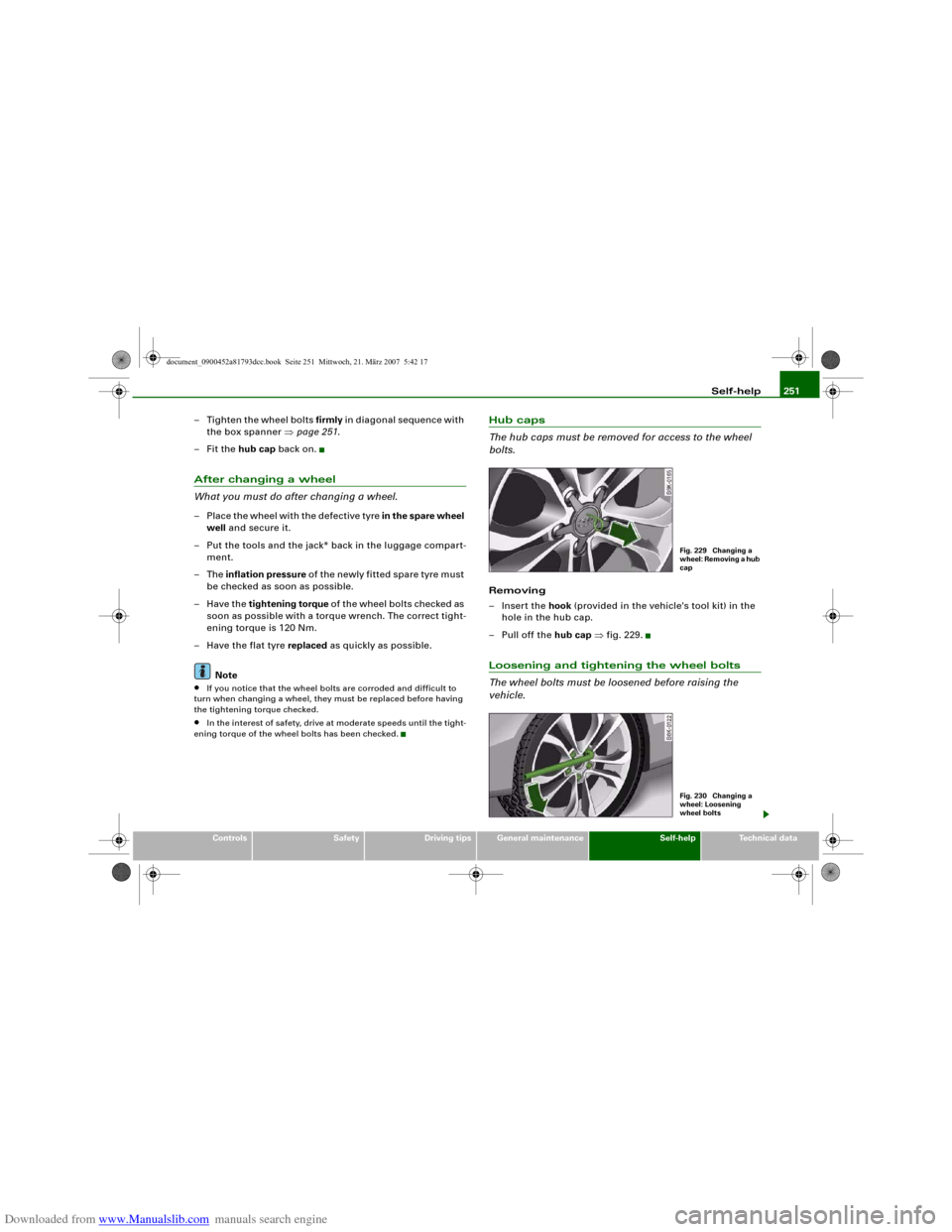
– Insert the hook (provided in the vehicle's tool kit) in the
hole in the hub cap.
–Pull off the hub cap ⇒fig. 229.Loosening and tightening the wheel bolts
The wheel bolts must be loosened before raising the
vehicle.
Fig. 229 Changing a
wheel: Removing a hub
capFig. 230 Changing a
wheel: Loosening
wheel bolts
document_0900452a81793dcc.book Seite 251 Mittwoch, 21. März 2007 5:42 17
Page 255 of 294
Downloaded from www.Manualslib.com manuals search engine Self-help253
Controls
Safety
Driving tips
General maintenance
Self-help
Technical data
– Now fit the crank handle onto the jack by inserting it
in the opening on the knob ⇒page 252, fig. 232. Turn the
crank handle clockwise or anti-clockwise to secure it in
place.
– Raise the vehicle by winding the crank handle until the
defective wheel is clear of the ground.Recesses at the front and rear of the door sills mark the jacking
points ⇒page 252, fig. 231. There is one jacking point for each
wheel. The distance from the jacking points to the wheel arches is
approximately 20 cm at the front and 40 cm at the rear. The jack may
only be applied at the seam of the jacking points shown.
An unstable surface under the jack may cause the vehicle to slip off
the jack. Always provide a firm base for the jack on the ground. If
necessary use a large, strong board or similar support. On a hard,
slippery surface (such as tiles) use a rubber mat or similar to prevent
the jack from slipping.
WARNING
•
Prevent the base of the jack from slipping – risk of injury.
•
The car can be damaged if the jack is not applied at the correct
jacking points. There is also a risk of injury since the jack can slip
off suddenly if it is not properly engaged.
Taking off the wheel and putting on the spare wheel
Step-by-step instructions for taking off the wheel and
putting on the spare wheel.Change the wheel as described below after loosening the
wheel bolts and raising the vehicle with the jack*.
Taking off the wheel
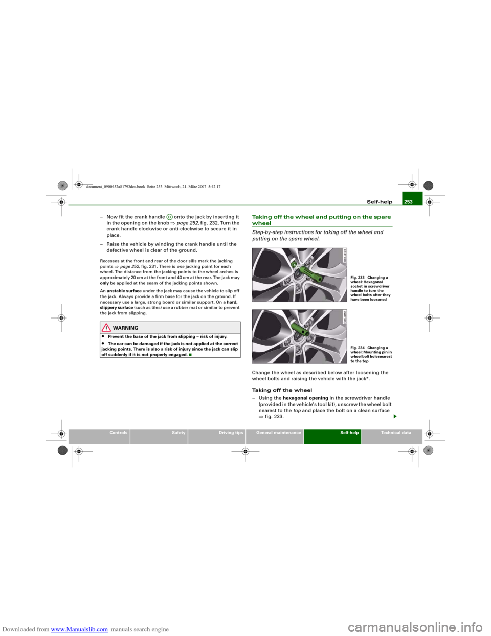
–Using the hexagonal opening in the screwdriver handle
(provided in the vehicle's tool kit), unscrew the wheel bolt
nearest to the top and place the bolt on a clean surface
⇒fig. 233.
AD
Fig. 233 Changing a
wheel: Hexagonal
socket in screwdriver
handle to turn the
wheel bolts after they
have been loosenedFig. 234 Changing a
wheel: Mounting pin in
wheel bolt hole nearest
to the top
document_0900452a81793dcc.book Seite 253 Mittwoch, 21. März 2007 5:42 17
Page 257 of 294
Downloaded from www.Manualslib.com manuals search engine Self-help255
Controls
Safety
Driving tips
General maintenance
Self-help
Technical data
– Insert the hook (provided in the vehicle's tool kit) in the
hole in the hub cap.
–Pull off the hub cap ⇒page 251, fig. 229.
– Insert the adapter completely into the wheel bolt .
– F i t t h e b o x s p a n n e r as f a r as i t w i l l g o o v e r t h e a d a p t e r .
– Loosen or tighten the wheel bolt ⇒page 251.It is advisable to carry the wheel bolt adapter in the vehicle. The
adapter is normally stored in the vehicle tool kit, underneath the
towline anchorage. It should be put back there after use.
The code number of the anti-theft wheel bolt is stamped on the front
o f t h e a d a p t e r. Yo u r A u d i d e a l e r w i l l n e e d t h i s n u m b e r t o r e p l a c e t h e
adapter if lost.
Note
Note the code number of the anti-theft wheel bolt and keep it in a
safe place – not in your vehicle.Jump-startingBefore starting the engine
If necessary, the engine can be started by connecting it to
the battery of another vehicle.If the engine should ever fail to start because of a discharged
battery, the battery can be connected to the battery of another
vehicle to start the engine. Suitable jump leads are required.
Both batteries must be rated at 12 Volts. The capacity (Ah) of the
booster battery should not be significantly lower than that of the
discharged battery.Jump leads
The jump leads must be heavy enough to carry the starter current.
Refer to the details given by the manufacturer.
Only use jump leads with insulated battery clamps.
Positive cable – usually red
Negative cable – usually black
WARNING
•
When it is discharged the battery can freeze at temperatures
around 0°C. A frozen battery must first be thawed out before
connecting the jump leads, as it could otherwise explode.
•
Please note the safety warnings referring to working in the
engine compartment ⇒page 221.Note
•
There must be no contact between the two vehicles as otherwise
current could flow as soon as the positive terminals are connected.
•
The discharged battery must be properly connected to the
vehicle's electrical system.
•
Switch off the car telephone if necessary. Details will be given in
the manufacturer's instructions for the car telephone.
A2
A1A2
document_0900452a81793dcc.book Seite 255 Mittwoch, 21. März 2007 5:42 17
Page 259 of 294
Downloaded from www.Manualslib.com manuals search engine Self-help257
Controls
Safety
Driving tips
General maintenance
Self-help
Technical data terminal must not touch metal parts of the vehicle: this can cause
short circuiting.
•
Do not bend over the batteries – risk of acid burns.
•
The screw plugs on the battery cells must be screwed in firmly.
•
Keep sparks, flame and lighted cigarettes away from batteries:
the gases given off can cause an explosion.
•
If jump-starting another vehicle, position the jump leads in
such a way that they cannot come into contact with any moving
parts in the engine compartment of the other vehicle.Caution
Please note that the above method of connecting the leads is meant
for jump-starting your vehicle. If jump-starting another vehicle, you
should not connect the negative lead (–) to the negative terminal of
the discharged battery, but directly to the engine block or a solid
metal part bolted to the engine block. If the battery of the other
vehicle does not have a gas vent, there is a risk that a mixture of
oxygen and hydrogen gas can accumulate and cause an
explosion.Tow-starting and towing awayGeneral notes
Points to observe when tow-starting or towing awayIf you use a towrope:
Notes for the driver of the towing vehicle
– The towrope must be taut before driving off.– Engage the clutch very gently when starting to move; on
vehicles with automatic gearbox press the accelerator
slowly.
Notes for the driver of the towed vehicle
– The ignition should be switched on so that the turn
signals, horn, windscreen wipers and washers can be
used. Please ensure that the steering wheel is unlocked
when you switch on the ignition, and that it moves freely.
–Put gear lever in neutral (manual gearbox) or move
selector lever to position N (automatic gearbox).
– The brake servo and power steering only work when the
engine is running. Considerably more effort is required
on the brake pedal and steering wheel when the engine
is switched off.
– Ensure that the towrope remains taut at all times when
towing.
Towrope or towbar
It is easier and safer to tow a vehicle with a towbar. You should only
use a towrope if you do not have a towbar.
A towrope should be slightly elastic to reduce the loading on both
vehicles. It is advisable to use a towrope made of synthetic fibre or
similar material.
Attach the tow-rope or tow-bar only to the towing anchorages
intended for this purpose ⇒page 258 or ⇒page 259.
Driving technique
Towing requires some experience – especially when using a
towrope. Both drivers should be familiar with the technique required
for towing. Inexperienced drivers should not attempt to tow-start or
tow away another vehicle.
WARNING (continued)
document_0900452a81793dcc.book Seite 257 Mittwoch, 21. März 2007 5:42 17
Page 261 of 294
Downloaded from www.Manualslib.com manuals search engine Self-help259
Controls
Safety
Driving tips
General maintenance
Self-help
Technical data
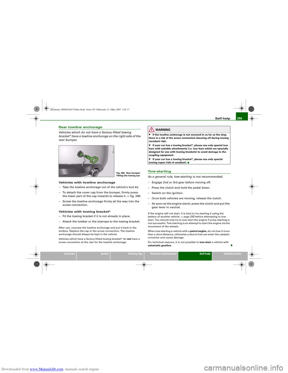
Rear towline anchorage
Vehicles which do not have a factory-fitted towing
bracket* have a towline anchorage on the right side of the
rear bumper.Vehicles with towline anchorage
– Take the towline anchorage out of the vehicle's tool kit.
– To detach the cover cap from the bumper, firmly press
the lower part of the cap inwards to release it ⇒fig. 240.
– Screw the towline anchorage firmly all the way into the
screw connection.
Vehicles with towing bracket*
– Fit the towing bracket if it is not already in place.
– Attach the towbar or the towrope to the towing bracket.After use, unscrew the towline anchorage and put it back in the
toolbox. Replace the cap in the screw connection. The towline
anchorage should always be kept in the vehicle.
Vehicles which have a factory-fitted towing bracket* do not have a
screw connection at the rear for the towline anchorage.
WARNING
•
If the towline anchorage is not screwed in as far as the stop,
there is a risk of the screw connection shearing off during towing
(accident risk).
•
If your car has a towing bracket*, please use only special tow
bars with suitable attachments (i.e. tow bars which are specially
designed for use with towing brackets) to avoid damage to the
coupling equipment.
•
If your car has a towing bracket*, please use only special
towing ropes (risk of accident).
To w - s t a r t i n g
As a general rule, tow-starting is not recommended.– Engage 2nd or 3rd gear before moving off.
– Press the clutch and hold the pedal down.
– Switch on the ignition.
– Once both vehicles are moving, release the clutch.
– As soon as the engine starts: press the clutch and put the
gear lever in neutral.If the engine will not start, it is best to try starting it using the
battery of another vehicle ⇒page 255 before attempting to tow
start. You should only try to tow-start the engine if jump-starting is
not successful. Tow-starting is an attempt to start the engine via the
movement of the wheels.
When tow-starting a vehicle with a petrol engine, do not tow it more
than a short distance, otherwise unburnt fuel can enter the catalytic
converter and cause damage.
For technical reasons, it is not possible to tow-start a vehicle with
automatic gearbox.
Fig. 240 Rear bumper:
Fitting the towing eye
document_0900452a81793dcc.book Seite 259 Mittwoch, 21. März 2007 5:42 17
Page 263 of 294
Downloaded from www.Manualslib.com manuals search engine Fuses and bulbs261
Controls
Safety
Driving tips
General maintenance
Self-help
Technical data
Fuses and bulbsFusesChanging a fuse
If a fuse has blown it must be replaced.– Identify the fuse for the failed component.
– Switch off the ignition and the component concerned.
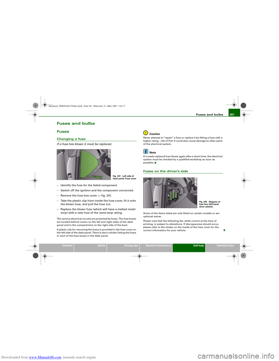
– Remove the fuse box cover ⇒fig. 241.
– Take the plastic clip from inside the fuse cover, fit it onto
the blown fuse, and pull the fuse out.
– Replace the blown fuse (which will have a melted metal
strip) with a new fuse of the same amp rating.The various electrical circuits are protected by fuses. The fuse boxes
are located behind covers on the left and right sides of the dash
panel and in the compartment on the right side of the boot.
A plastic clip for removing the fuses is provided in the fuse cover on
the left side of the dash panel. There is also a sticker listing the fuses
in each of the fuse boxes in the dash panel.
Caution
Never attempt to “repair” a fuse or replace it by fitting a fuse with a
higher rating - risk of fire! It could also cause damage to other parts
of the electrical system.
Note
If a newly replaced fuse blows again after a short time, the electrical
system must be checked by a qualified workshop as soon as
possible.Fuses on the driver's sideSome of the items listed are only fitted on certain models or are
optional extras.
Please note that the following list, while correct at the time of
printing, is subject to alterations. If discrepancies should occur,
please refer to the sticker on the inside of the fuse cover for the
correct information for your vehicle.
Fig. 241 Left side of
dash panel: Fuse cover
Fig. 242 Diagram of
fuse box (left-hand
drive vehicle)
document_0900452a81793dcc.book Seite 261 Mittwoch, 21. März 2007 5:42 17
Page 265 of 294
Downloaded from www.Manualslib.com manuals search engine Fuses and bulbs263
Controls
Safety
Driving tips
General maintenance
Self-help
Technical data
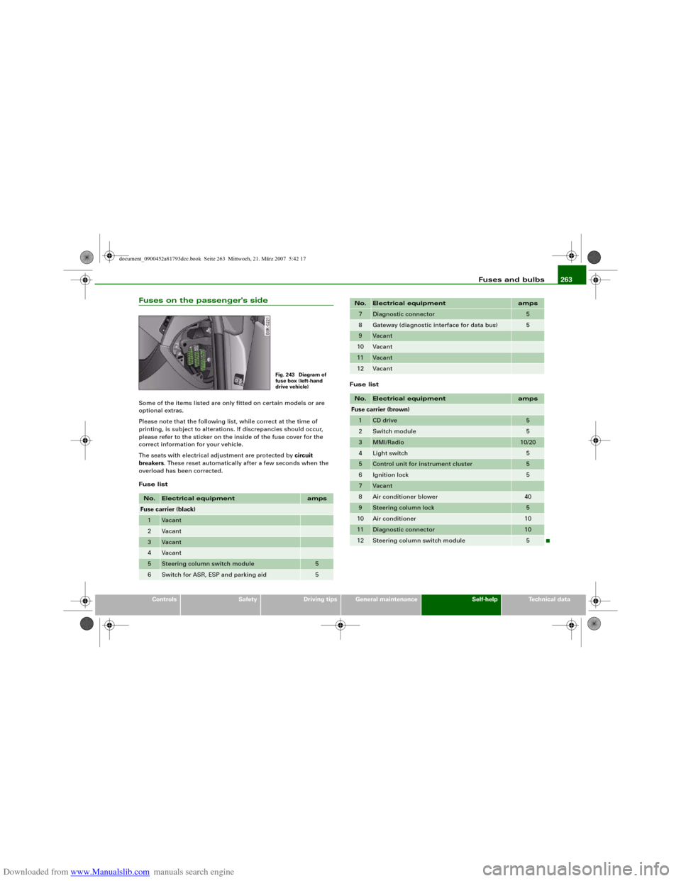
Fuses on the passenger's sideSome of the items listed are only fitted on certain models or are
optional extras.
Please note that the following list, while correct at the time of
printing, is subject to alterations. If discrepancies should occur,
please refer to the sticker on the inside of the fuse cover for the
correct information for your vehicle.
The seats with electrical adjustment are protected by circuit
breakers. These reset automatically after a few seconds when the
overload has been corrected.
Fuse listFuse listNo.
Electrical equipment
amps
Fuse carrier (black)1
Vacant
2
Vacant
3
Vacant
4
Vacant
5
Steering column switch module
5
6
Switch for ASR, ESP and parking aid
5
Fig. 243 Diagram of
fuse box (left-hand
drive vehicle)
7
Diagnostic connector
5
8
Gateway (diagnostic interface for data bus)
5
9
Vacant
10
Vacant
11
Vacant
12
Vacant
No.
Electrical equipment
amps
Fuse carrier (brown)1
CD drive
5
2
Switch module
5
3
MMI/Radio
10/20
4
Light switch
5
5
Control unit for instrument cluster
5
6
Ignition lock
5
7
Vacant
8
Air conditioner blower
40
9
Steering column lock
5
10
Air conditioner
10
11
Diagnostic connector
10
12
Steering column switch module
5
No.
Electrical equipment
amps
document_0900452a81793dcc.book Seite 263 Mittwoch, 21. März 2007 5:42 17
Page 267 of 294
Downloaded from www.Manualslib.com manuals search engine Fuses and bulbs265
Controls
Safety
Driving tips
General maintenance
Self-help
Technical data
BulbsChanging bulbs
Changing bulbs requires a certain degree of practical
skill.You can change the following bulbs for exterior lights yourself:•
Bulb for turn signals
•
Bulb for fog light
•
Bulbs for rear lights in boot lid
•
Bulbs for rear lights in side panel
•
Bulbs for number plate light
The following bulbs should only be changed by a qualified work-
shop:
•
Xenon headlights: Light source for daytime running
lights/parking lights
•
Bulb for headlights: Bi-xenon lights ⇒
•
Light source for turn signal in exterior mirror housing
•
Light source for high-level brake light
As a rule, you require a certain degree of practical skill to change
defective bulbs. This applies in particular to those bulbs which are
only accessible from the engine compartment.
If in doubt, we recommend that you have defective bulbs changed
by a qualified workshop or qualified mechanic.
If you do decide to change bulbs in the engine compartment your-
self, be aware of the safety risks involved ⇒page 221 ⇒.
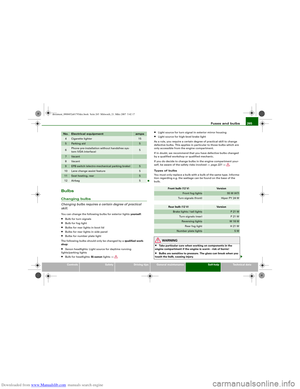
Types of bulbs
You must only replace a bulb with a bulb of the same type. Informa-
tion regarding e.g. the wattage can be found on the base of the
bulb.
WARNING
•
Take particular care when working on components in the
engine compartment if the engine is warm - risk of burns!
•
Bulbs are sensitive to pressure. The glass can break when you
touch the bulb, causing injury.
4
Cigarette lighter
15
5
Parking aid
5
6
Phone pre-installation without handsfree sys-
tem (VDA interface)
5
7
Vacant
8
Vacant
9
EPB switch (electro-mechanical parking brake)
5
10
Lane change assist feature
5
11
Seat heating, rear
5
12
Airbag
5
No.
Electrical equipment
amps
Front bulb (12 V)
Version
Front fog lights
55 W (H7)
Turn signals (front)
Hiper PY 24 W
Rear bulb (12 V)
Version
Brake lights / tail lights
P 21 W
Turn signals (rear)
P 21 W
Reversing lights
W 16 W
Rear fog light
H 21 W
Number plate lights
5 W
document_0900452a81793dcc.book Seite 265 Mittwoch, 21. März 2007 5:42 17