2008 AUDI S5 service interval
[x] Cancel search: service intervalPage 22 of 294
Downloaded from www.Manualslib.com manuals search engine Driver information system 20Driver information systemIntroductionGeneral notes
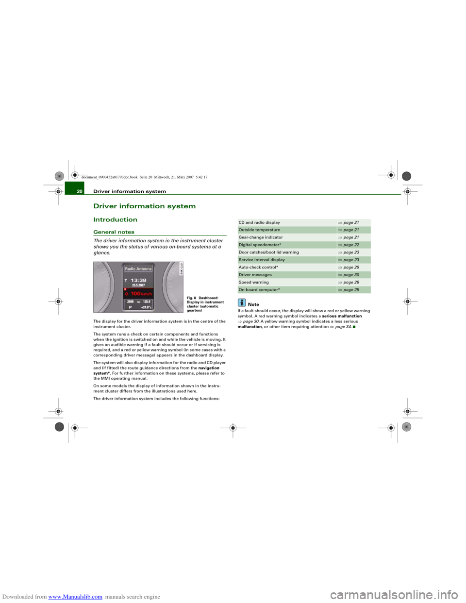
The driver information system in the instrument cluster
shows you the status of various on-board systems at a
glance.The display for the driver information system is in the centre of the
instrument cluster.
The system runs a check on certain components and functions
when the ignition is switched on and while the vehicle is moving. It
gives an audible warning if a fault should occur or if servicing is
required, and a red or yellow warning symbol (in some cases with a
corresponding driver message) appears in the dashboard display.
The system will also display information for the radio and CD player
and (if fitted) the route guidance directions from the navigation
system*. For further information on these systems, please refer to
the MMI operating manual.
On some models the display of information shown in the instru-
ment cluster differs from the illustrations used here.
The driver information system includes the following functions:
Note
If a fault should occur, the display will show a red or yellow warning
symbol. A red warning symbol indicates a serious malfunction
⇒page 30. A yellow warning symbol indicates a less serious
malfunction, or other item requiring attention ⇒page 34.
Fig. 8 Dashboard:
Display in instrument
cluster (automatic
gearbox)
CD and radio display
⇒page 21
Outside temperature
⇒page 21
Gear-change indicator
⇒page 21
Digital speedometer*
⇒page 22
Door catches/boot lid warning
⇒page 23
Service interval display
⇒page 23
Auto-check control*
⇒page 29
Driver messages
⇒page 30
Speed warning
⇒page 28
On-board computer*
⇒page 25
document_0900452a81793dcc.book Seite 20 Mittwoch, 21. März 2007 5:42 17
Page 25 of 294
Downloaded from www.Manualslib.com manuals search engine Driver information system23
Controls
Safety
Driving tips
General maintenance
Self-help
Technical data
Door catches / boot lid warning
The pictogram shows whether the doors and the boot lid,
etc. are properly closed when driving off.The door catches/boot lid warning symbol lights up if one or more
of the doors, or the bonnet or boot lid are not properly closed when
the ignition is on. The symbol also indicates which of these is not
properly closed ⇒fig. 14.
The warning symbol disappears when all the doors, the bonnet and
the boot lid are completely closed, and the driver information func-
tions selected will then be displayed again.
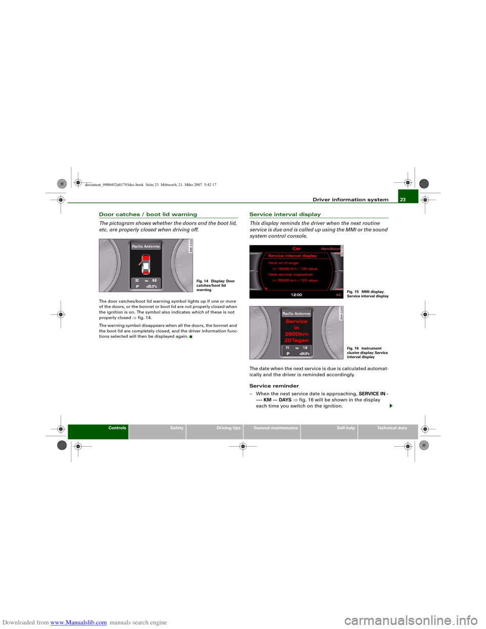
Service interval display
This display reminds the driver when the next routine
service is due and is called up using the MMI or the sound
system control console.The date when the next service is due is calculated automat-
ically and the driver is reminded accordingly.
Service reminder
– When the next service date is approaching, SERVICE IN -
---- KM --- DAYS ⇒fig. 16 will be shown in the display
each time you switch on the ignition.
Fig. 14 Display: Door
catches/boot lid
warning
Fig. 15 MMI display:
Service interval displa
y
Fig. 16 Instrument
cluster display: Service
interval display
document_0900452a81793dcc.book Seite 23 Mittwoch, 21. März 2007 5:42 17
Page 26 of 294
Downloaded from www.Manualslib.com manuals search engine Driver information system 24
– The remaining time and distance to the next service are
indicated every time the ignition is switched on, until the
service becomes due.
Service due
–When a service is due, Service! will appear in the display
as soon as you switch on the ignition. The display reverts
back to the standard display after about 5 seconds.
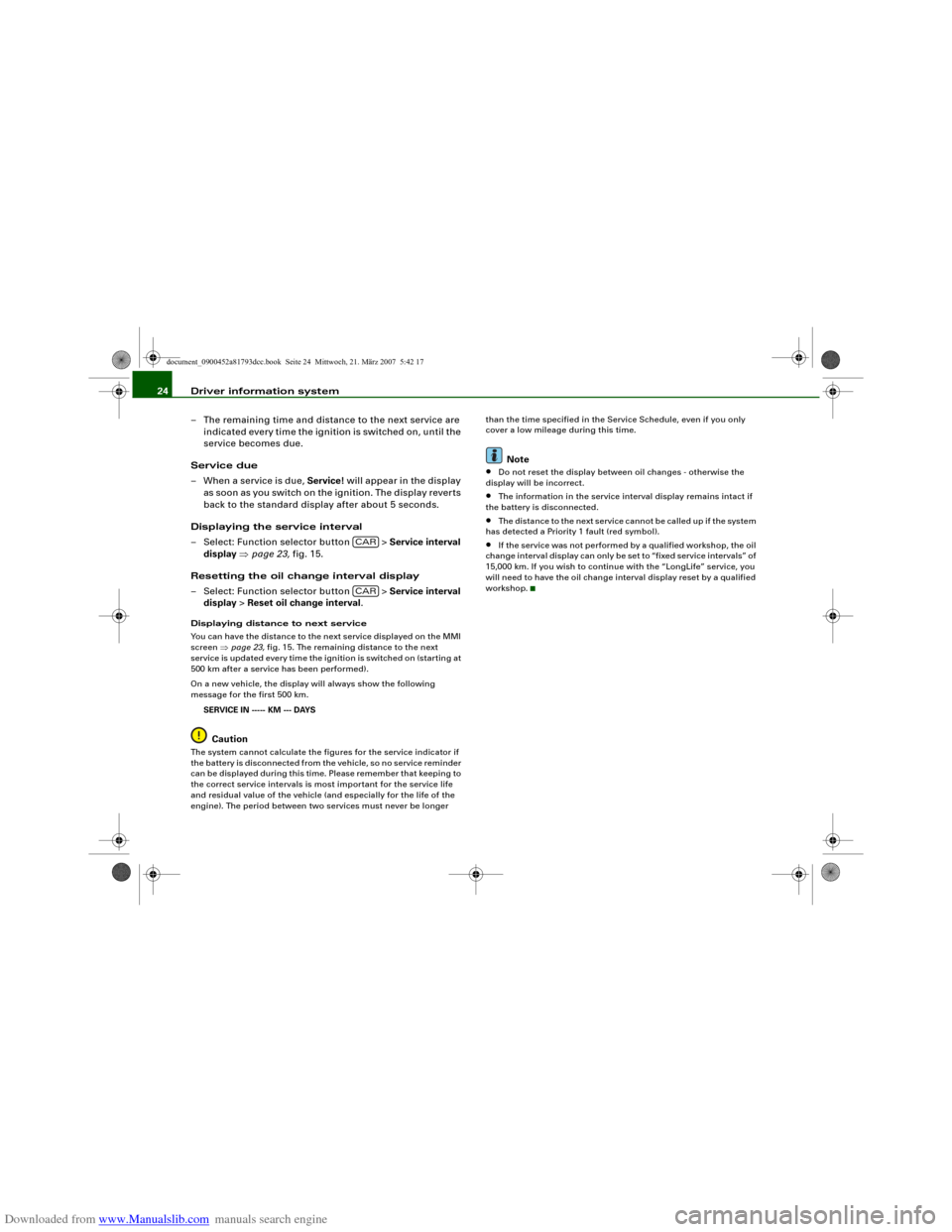
Displaying the service interval
– Select: Function selector button > Service interval
display ⇒page 23, fig. 15.
Resetting the oil change interval display
– Select: Function selector button > Service interval
display > Reset oil change interval.Displaying distance to next service
You can have the distance to the next service displayed on the MMI
screen ⇒page 23, fig. 15. The remaining distance to the next
service is updated every time the ignition is switched on (starting at
500 km after a service has been performed).
On a new vehicle, the display will always show the following
message for the first 500 km.
SERVICE IN ----- KM --- DAYS
Caution
The system cannot calculate the figures for the service indicator if
the battery is disconnected from the vehicle, so no service reminder
can be displayed during this time. Please remember that keeping to
the correct service intervals is most important for the service life
and residual value of the vehicle (and especially for the life of the
engine). The period between two services must never be longer than the time specified in the Service Schedule, even if you only
cover a low mileage during this time.
Note
•
Do not reset the display between oil changes - otherwise the
display will be incorrect.
•
The information in the service interval display remains intact if
the battery is disconnected.
•
The distance to the next service cannot be called up if the system
has detected a Priority 1 fault (red symbol).
•
If the service was not performed by a qualified workshop, the oil
change interval display can only be set to “fixed service intervals” of
15,000 km. If you wish to continue with the “LongLife” service, you
will need to have the oil change interval display reset by a qualified
workshop.
CARCAR
document_0900452a81793dcc.book Seite 24 Mittwoch, 21. März 2007 5:42 17
Page 93 of 294
Downloaded from www.Manualslib.com manuals search engine Heating and cooling91
Controls
Safety
Driving tips
General maintenance
Self-help
Technical data
Heating and coolingDeluxe automatic air conditionerApplies to vehicles: with deluxe automatic air conditionerDescription
The air conditioner can be used to set a comfortable inte-
rior temperature in the vehicle.The air conditioner provides heating and ventilation and also cools
and dehumidifies the air inside the vehicle.
The air conditioner is fully automatic and will maintain the desired
temperature at a constant level. To achieve this, the temperature of
the air supplied to the interior, the blower speed (volume of air
delivery) and the air distribution are regulated automatically. The
system also allows for the effect of strong sunlight, so there is no
need for manual adjustment. For these reasons it is advisable to use
the automatic mode for the comfort of all the passengers in virtually
all conditions throughout the year ⇒page 93.
Please note:
The humidity of the air is automatically reduced when the system
cools the interior of the vehicle. This helps to prevent condensation
on the windows.
If the humidity and temperature outside the vehicle are high,
condensation can drip off the evaporator in the air cooling system
and form a pool underneath the vehicle. This is normal and does not
indicate a leak.
If the outside temperature is low, the blower normally only switches
to a higher speed once the coolant has warmed up sufficiently (this
does not apply to the defrost setting).
In order to achieve maximum engine power, the air conditioner
compressor is temporarily switched off when pulling away from a
standstill with full throttle.The compressor also switches off if the coolant temperature is
excessively high, to ensure adequate engine cooling under extreme
loads.
Pollution filter
The pollution filter (a particle filter) serves as a barrier against impu-
rities in the outside air, including dust and pollen, and odours. The
air is also filtered when the air recirculation mode is activated.
For the air conditioner to work with maximum efficiency, the pollu-
tion filter element must be replaced at the intervals specified in the
Service Schedule.
If the vehicle is driven in areas with a high level of air pollution and
the filter is no longer fully effective, it may be necessary to change
the filter element more frequently.
Key-coded settings
The currently selected air conditioner settings are automatically
stored and assigned to the remote control key.
Power management
To prevent the battery from becoming discharged and to maintain
the necessary power level, the system will temporarily shut off the
electrical components that are using a lot of power, or reduce the
current they are consuming ⇒page 192. Heating systems in partic-
ular use a large amount of electrical power. If you notice, for
instance, that the rear window heater is not working, it may have
been temporarily switched off by the power management function,
or regulated to a lower heat output. These systems will be available
again as soon as sufficient electrical power is available.
document_0900452a81793dcc.book Seite 91 Mittwoch, 21. März 2007 5:42 17
Page 101 of 294
Downloaded from www.Manualslib.com manuals search engine Heating and cooling99
Controls
Safety
Driving tips
General maintenance
Self-help
Technical data
– Select the desired air conditioner settings using the
rotary pushbutton ⇒page 98, fig. 112.The following functions are available:•
Auxiliary heating* ⇒page 108
•
Auxiliary ventilation* ⇒page 108
•
Running time* ⇒page 111
•
Timer status* ⇒page 110
•
Timer 1* ⇒page 110
•
Timer 2* ⇒page 110
•
Timer 3* ⇒page 110
Deluxe automatic air conditioner plusApplies to vehicles: with deluxe automatic air conditioner plusDescription
The air conditioner is designed to keep the passenger
compartment at the temperature you find most comfort-
able at all times of the year.The air conditioner provides heating and ventilation and also cools
and dehumidifies the air inside the vehicle.
The air conditioner is fully automatic, and will maintain the desired
temperature at a constant level. To achieve this, the temperature of
the air supplied to the interior, the blower speed (volume of air
delivery) and the air distribution are regulated automatically. The
system also allows for the effect of strong sunlight, so there is no
need for manual adjustment. For these reasons it is advisable to use
the automatic mode for the comfort of all the passengers in virtually
all conditions throughout the year ⇒page 101.
Please note:The humidity of the air is automatically reduced when the system
cools the interior of the vehicle. This helps to prevent condensation
on the windows.
If the humidity and temperature outside the vehicle are high,
condensation can drip off the evaporator in the air cooling system
and form a pool underneath the vehicle. This is normal and does not
indicate a leak.
If the outside temperature is low, the blower normally only switches
to a higher speed once the coolant has warmed up sufficiently (this
does not apply to the defrost setting).
In order to achieve maximum engine power, the air conditioner
compressor is temporarily switched off when pulling away from a
standstill with full throttle.
The compressor also switches off if the coolant temperature is
excessively high, to ensure adequate engine cooling under extreme
loads.
Pollution filter
The pollution filter (a combined particle filter and activated charcoal
filter) serves as a barrier against impurities in the outside air,
including dust and pollen, and against unpleasant smells. The air is
also filtered when the air recirculation mode is activated.
For the air conditioner to work with maximum efficiency, the pollu-
tion filter element must be replaced at the intervals specified in the
Service Schedule.
If the vehicle is driven in areas with a high level of air pollution and
the filter is no longer fully effective, it may be necessary to change
the filter element more frequently.
Key-coded settings
The currently selected air conditioner settings are automatically
stored and assigned to the remote control key.
document_0900452a81793dcc.book Seite 99 Mittwoch, 21. März 2007 5:42 17
Page 201 of 294
Downloaded from www.Manualslib.com manuals search engine Towing a trailer199
Controls
Safety
Driving tips
General maintenance
Self-help
Technical data additional mirrors fitted. Both exterior mirrors should be mounted
on hinged extension brackets. Adjust the mirrors to give sufficient
vision to the rear.
Power supply
When you remove the ignition key the power supply to the trailer is
interrupted.
Removable ball joint coupling
Vehicles with a factory-fitted towing bracket are equipped with a
removable ball joint coupling. It is carried under the floor panel on
the left-hand side of the luggage compartment.
Note
We recommend having the car serviced between the normal inspec-
tion intervals if it used frequently for towing a trailer.Applies to vehicles: with towing bracketTrailer stabilisation system
Trailer stabilisation helps to reduce the risk of the vehicle
skidding when towing a trailer.When is the trailer stabilisation system activated?
Trailer stabilisation is active when the following requirements are
met:•
The ESP must NOT be switched off ⇒page 186,
•
The trailer connector must be properly secured in the vehicle
socket.
•
Vehicle speed must be higher than approx. 60 km/h.
How trailer stabilisation works:
In many cases, the driver can stabilise a swaying trailer by manually
braking the vehicle.However, if the ESP detects that the trailer is swaying and this is
affecting the towing vehicle, it will automatically brake the vehicle
to stabilise the trailer by slowing it down. The warning lamp
will
light up in the instrument cluster. If possible, do not turn the
steering wheel at this stage.
In order to warn traffic behind you, the brake lights will come on
during this automatic braking operation.
A trailer weighing less than 70% of the kerb weight of the towing
vehicle may sway quite considerably without the trailer stabilisation
system intervening. This can happen when the swaying movements
of the light-weight trailer are not or hardly passed on to the towing
vehicle and are therefore not detected by the ESP.
If the system for activating the trailer brake lights is defective, this
will be indicated in the instrument cluster display ⇒page 36, “Bulb
monitor ”.
Requirements for correct functioning of the trailer
stabilisation system
If these conditions are not met in full, the trailer stabilisation system
will only intervene to a limited extent or not at all ⇒.
•
The electrical connection between the towing vehicle and the
trailer must be functioning correctly, without any defects.
•
The load on the trailer must be properly secured.
•
The tyre pressures on both the vehicle and the trailer must be
adapted to the load that is being carried.
•
Where possible, operate the trailer with the maximum permitted
draw bar weight.
•
The trailer overrun brake must be set correctly. This is important
to ensure that the trailer can be braked correctly, to avoid the vehicle
and trailer “jack-knifing” and to prevent excess braking of the trailer.
•
In low outside temperatures, both the towing vehicle and the
trailer should be fitted with winter tyres.
document_0900452a81793dcc.book Seite 199 Mittwoch, 21. März 2007 5:42 17
Page 224 of 294
Downloaded from www.Manualslib.com manuals search engine Checking and topping up fluids 222
WARNING
•
For safety reasons the bonnet must always be completely
closed when the vehicle is moving. After closing it always check
that it is properly secured. The bonnet must be flush with the adja-
cent body panels.
•
Should you notice that the bonnet is not safely secured when
the vehicle is moving, stop the vehicle immediately and close the
bonnet properly, otherwise it could cause an accident.
Engine compartment layoutEngine compartment layout
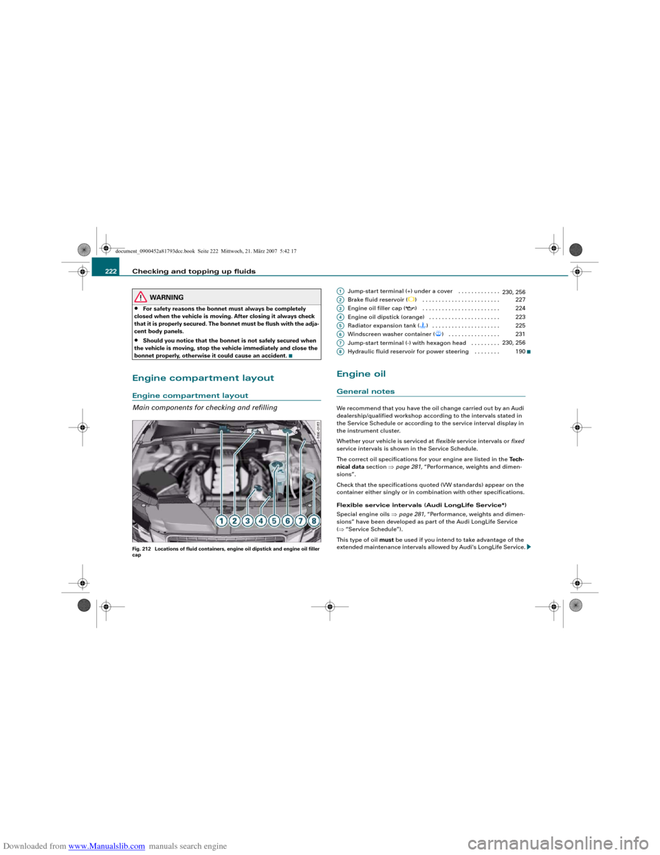
Main components for checking and refillingFig. 212 Locations of fluid containers, engine oil dipstick and engine oil filler
cap
Jump-start terminal (+) under a cover . . . . . . . . . . . . .
Brake fluid reservoir (
) . . . . . . . . . . . . . . . . . . . . . . . .
Engine oil filler cap (
) . . . . . . . . . . . . . . . . . . . . . . . .
Engine oil dipstick (orange) . . . . . . . . . . . . . . . . . . . . . .
Radiator expansion tank () . . . . . . . . . . . . . . . . . . . . .
Windscreen washer container (
) . . . . . . . . . . . . . . . .
Jump-start terminal (-) with hexagon head . . . . . . . . .
Hydraulic fluid reservoir for power steering . . . . . . . .
Engine oilGeneral notesWe recommend that you have the oil change carried out by an Audi
dealership/qualified workshop according to the intervals stated in
the Service Schedule or according to the service interval display in
the instrument cluster.
Whether your vehicle is serviced at flexible service intervals or fixed
service intervals is shown in the Service Schedule.
The correct oil specifications for your engine are listed in the Tech-
nical data section ⇒page 281, “Performance, weights and dimen-
sions”.
Check that the specifications quoted (VW standards) appear on the
container either singly or in combination with other specifications.
Flexible service intervals (Audi LongLife Service*)
Special engine oils ⇒page 281, “Performance, weights and dimen-
sions” have been developed as part of the Audi LongLife Service
(⇒“Service Schedule”).
This type of oil must be used if you intend to take advantage of the
extended maintenance intervals allowed by Audi's LongLife Service.A1
230, 256
A2
227
A3
224
A4
223
A5
225
A6
231
A7
230, 256
A8
190
document_0900452a81793dcc.book Seite 222 Mittwoch, 21. März 2007 5:42 17
Page 225 of 294
Downloaded from www.Manualslib.com manuals search engine Checking and topping up fluids223
Controls
Safety
Driving tips
General maintenance
Self-help
Technical data
•
Do not mix the LongLife oil with oil intended for fixed service
intervals, as the requirements for the extended service intervals are
then no longer guaranteed.
•
In exceptional circumstances, if the engine oil level is too low
⇒page 223 and you cannot obtain the specified LongLife oil, you
can put in a small quantity of oil for fixed service intervals -
⇒page 281, “Performance, weights and dimensions”. This should
not be done more than once and no more than 0.5 litres should be
used.
Fixed service intervals (Inspection Service)*
If you do not take advantage of the Audi LongLife service for your
car, you can use the oils for fixed service intervals - ⇒page 281,
“Performance, weights and dimensions”. In this case, your car must
be serviced after a fixed interval of 1 year / 15,000 km (10,000 miles)
– see Service Schedule.
•
In exceptional circumstances, if the engine oil level is too low
⇒page 223 and you cannot obtain the oil specified for your vehicle,
you can put in a small quantity of oil conforming to the specification
ACEA A2 or ACEA A3. This should not be done more than once and
no more than 0.5 litres should be used.
Checking the oil level
Checking oil level
– Park your vehicle on a level surface.
– Allow the warm engine to run briefly at idling speed and
then switch off the ignition.
– Wait approx. 2 minutes.
– Pull out the dipstick. Wipe the dipstick with a clean cloth
and insert it again, pushing it in as far as it will go.
– Then pull the dipstick out again and check the oil level
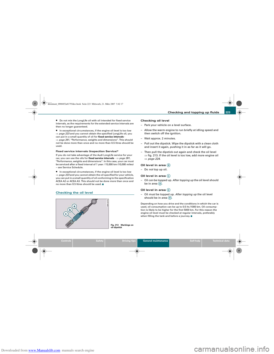
⇒fig. 213. If the oil level is too low, add more engine oil
⇒page 224.
Oil level in area
–Do not top up oil.
Oil level in area
–Oil can be topped up. After topping up the oil level should
be in area .
Oil level in area
–Oil must be topped up. After topping up the oil level
should be in area .Depending on how you drive and the conditions in which the car is
used, oil consumption can be up to 0.5 ltr./1000 km. Oil consump-
tion is likely to be higher for the first 5000 km. For this reason the
engine oil level must be checked at regular intervals, preferably
when filling the tank and before a journey.
Fig. 213 Markings on
oil dipstick
AaAb
Aa
AcAa
document_0900452a81793dcc.book Seite 223 Mittwoch, 21. März 2007 5:42 17