2008 AUDI A4 technical data
[x] Cancel search: technical dataPage 67 of 342
Lights and vision65
Controls
Safety
Driving tips
General maintenance
Self-help
Technical data
– To retract the sun blind automatically when reversing,
select: Function selector button > Windows >
Automatic rear blind > on.If you switch the Automatic rear blind function on in the sound
system or MMI*, the raised sun blind will be retracted automatically
when reverse gear is engaged ⇒page 55. In this way, the rear blind
will not obstruct your vision when reversing. The rear blind returns
to its raised position when reverse gear is disengaged and the
vehicle is driven forwards at a speed above about 15 km/h. The
current setting is automatically stored and assigned to the remote
control key.
If the rear blind was rolled in automatically when reversing and then
the ignition was switched off and on again, the blind will not roll
back out again when you select a forward gear and the speed
exceeds 15 km/h. You will then have to press the button
on the
centre console to extend the blind again.
The sun blind for the rear window switches off automatically when
it reaches the end position. It can be made to move in the other
direction before it reaches its end position by briefly pressing the
switch a second time. If the ignition is turned off while the blind is
still moving, it continues until it reaches the end position before
switching off.
Note
•
An overload cut-out may be activated if the sun blind is operated
repeatedly. There will then be a short delay before the blind can be
operated again.
•
As the material of the sun blind is less flexible at low tempera-
tures the electric actuator is switched off when the temperature in
the car is below -5°C. The blind can only be operated when the
temperature in the car's interior rises above this level.
Windscreen wipersWindscreen wipers
The windscreen wiper lever controls the windscreen
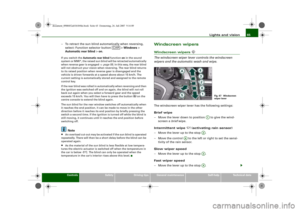
wipers and the automatic wash and wipe.The windscreen wiper lever has the following settings:
Brief wipe
– Move the lever down to position to give the wind-
screen a brief wipe.
Intermittent wipe
(activating rain sensor)
– Move the lever up to the stop .
– Move the control to the left or right to set the sensi-
tivity of the rain sensor.
Slow wiper speed
– Move the lever up to the stop .
Fast wiper speed
– Move the lever up to the stop .
CAR
Fig. 67 Windscreen
wiper lever
A1
A2
AA
A3A4
document_0900452a81b1b9de.book Seite 65 Donnerstag, 26. Juli 2007 9:16 09
Page 69 of 342
Lights and vision67
Controls
Safety
Driving tips
General maintenance
Self-help
Technical data
Note
•
Check that the washer fluid reservoir is full before starting a long
journey. Filling the reservoir ⇒page 267.
•
Worn or dirty wiper blades can cause smearing on the glass
which can also impair the effectiveness of the rain sensor. Please
check the wiper blades regularly.
Applies to vehicles: with headlight washersHeadlight washer systemThe headlight washer system only operates when the lights
are switched on.
– Move the automatic wash and wipe lever to position
⇒page 65, fig. 67.The headlight washer system is always activated the first time you
operate the automatic wash and wipe. Subsequently, it is only acti-
vated about every five wash and wipe cycles. The headlights are
always washed if you hold the lever for longer than about
2seconds.
The headlight washer jets come out of the bumper automatically
(under water pressure).
Clean off stubborn dirt (insects, etc.) from the lenses at regular
intervals, for instance when stopping for fuel.
To ensure that the system works properly in winter, keep the nozzle
holders free of snow and remove any ice with a de-icer spray.
Service position
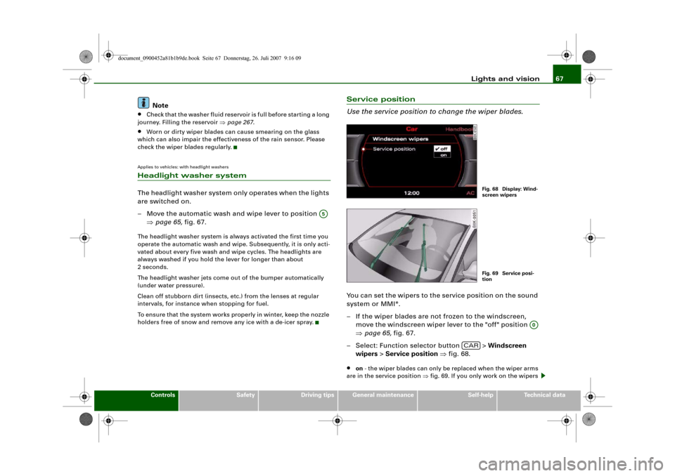
Use the service position to change the wiper blades.You can set the wipers to the service position on the sound
system or MMI*.
– If the wiper blades are not frozen to the windscreen,
move the windscreen wiper lever to the "off" position
⇒page 65, fig. 67.
– Select: Function selector button > Windscreen
wipers > Service position ⇒fig. 68.•
on - the wiper blades can only be replaced when the wiper arms
are in the service position ⇒fig. 69. If you only work on the wipers
A5
Fig. 68 Display: Wind-
screen wipersFig. 69 Service posi-
tion
A0
CAR
document_0900452a81b1b9de.book Seite 67 Donnerstag, 26. Juli 2007 9:16 09
Page 71 of 342
Lights and vision69
Controls
Safety
Driving tips
General maintenance
Self-help
Technical data
Anti-dazzle setting
– Pull the lever at the bottom of the mirror towards you.Applies to vehicles: with automatic anti-dazzle adjustment for interior mirrorAutomatic anti-dazzle adjustment
The automatic anti-dazzle function can be switched on
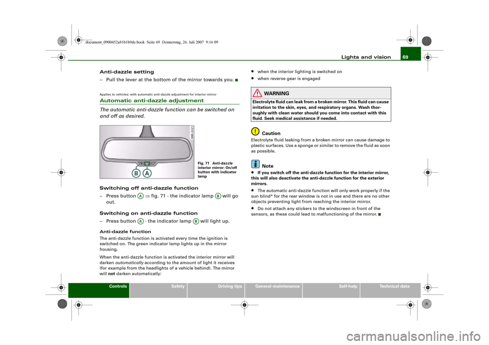
and off as desired.Switching off anti-dazzle function
– Press button ⇒fig. 71 - the indicator lamp will go
out.
Switching on anti-dazzle function
– Press button - the indicator lamp will light up.Anti-dazzle function
The anti-dazzle function is activated every time the ignition is
switched on. The green indicator lamp lights up in the mirror
housing.
When the anti-dazzle function is activated the interior mirror will
darken automatically according to the amount of light it receives
(for example from the headlights of a vehicle behind). The mirror
will not darken automatically:
•
when the interior lighting is switched on
•
when reverse gear is engaged
WARNING
Electrolyte fluid can leak from a broken mirror. This fluid can cause
irritation to the skin, eyes, and respiratory organs. Wash thor-
oughly with clean water should you come into contact with this
fluid. Seek medical assistance if needed.
Caution
Electrolyte fluid leaking from a broken mirror can cause damage to
plastic surfaces. Use a sponge or similar to remove the fluid as soon
as possible.
Note
•
If you switch off the anti-dazzle function for the interior mirror,
this will also deactivate the anti-dazzle function for the exterior
mirrors.
•
The automatic anti-dazzle function will only work properly if the
sun blind* for the rear window is not in use and there are no other
objects preventing light from reaching the interior mirror.
•
Do not attach any stickers to the windscreen in front of the
sensors, as these could lead to malfunctioning of the mirror.
Fig. 71 Anti-dazzle
interior mirror: On/off
button with indicator
lamp
AA
AB
AA
AB
document_0900452a81b1b9de.book Seite 69 Donnerstag, 26. Juli 2007 9:16 09
Page 73 of 342
Lights and vision71
Controls
Safety
Driving tips
General maintenance
Self-help
Technical data
Applies to vehicles: with automatic anti-dazzle adjustment for exterior mirrorsAutomatic anti-dazzle adjustment for exterior mirrorsThe exterior mirrors darken together with the automatically
adjusting interior mirror. When the ignition is on, the mirrors will
darken automatically according to the amount of light received (for
example from the headlights of a vehicle behind).
When the interior lights are switched on, or when reverse gear is
engaged, the mirrors revert to their original (i.e. not darkened)
condition.
WARNING
Electrolyte fluid can leak from a broken mirror. This fluid can cause
irritation to the skin, eyes, and respiratory organs. Wash thor-
oughly with clean water should you come into contact with this
fluid. Seek medical assistance if needed.
Caution
Electrolyte fluid leaking from a broken mirror can cause damage to
the paintwork or plastic surfaces. Use a sponge or similar to remove
the fluid as soon as possible.
Note
•
If you switch off the anti-dazzle function for the interior mirror,
this will also deactivate the anti-dazzle function for the exterior
mirrors.
•
The automatic anti-dazzle function will only work properly if the
sun blind* for the rear window is not in use and there are no other
objects preventing light from reaching the interior mirror.
Digital compassApplies to vehicles: with digital compassActivating and deactivating the compass
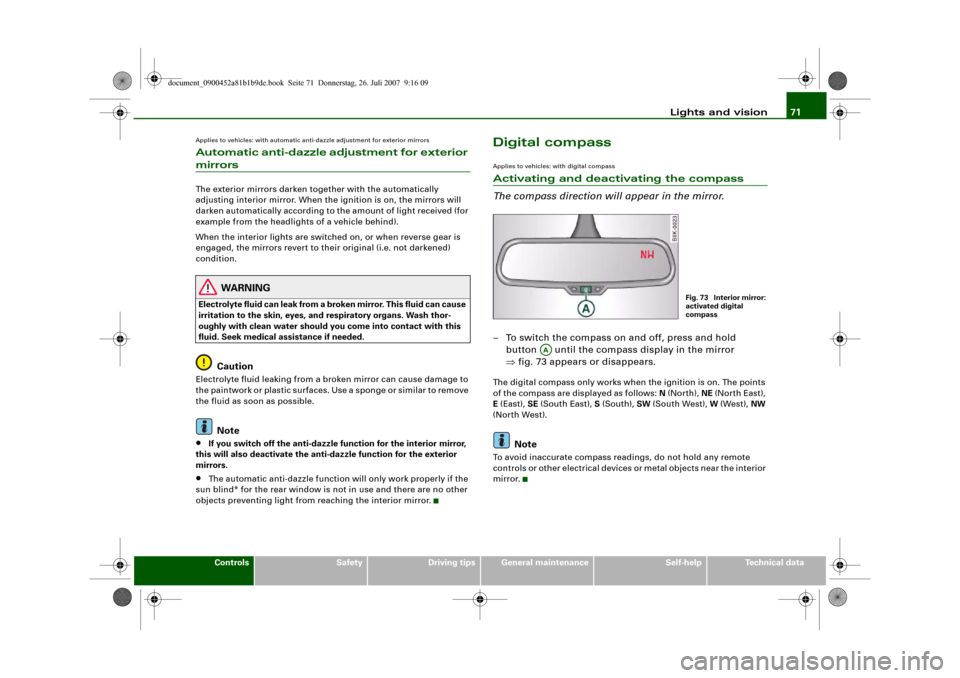
The compass direction will appear in the mirror.– To switch the compass on and off, press and hold
button until the compass display in the mirror
⇒fig. 73 appears or disappears.The digital compass only works when the ignition is on. The points
of the compass are displayed as follows: N (North), NE (North East),
E (East), SE (South East), S (South), SW (South West), W (West), NW
(North West).
Note
To avoid inaccurate compass readings, do not hold any remote
controls or other electrical devices or metal objects near the interior
mirror.
Fig. 73 Interior mirror:
activated digital
compass
AA
document_0900452a81b1b9de.book Seite 71 Donnerstag, 26. Juli 2007 9:16 09
Page 75 of 342
Seats and storage73
Controls
Safety
Driving tips
General maintenance
Self-help
Technical data
Seats and storageManual adjustment of front seatsApplies to vehicles: with manual seat adjustmentSeat adjuster controls
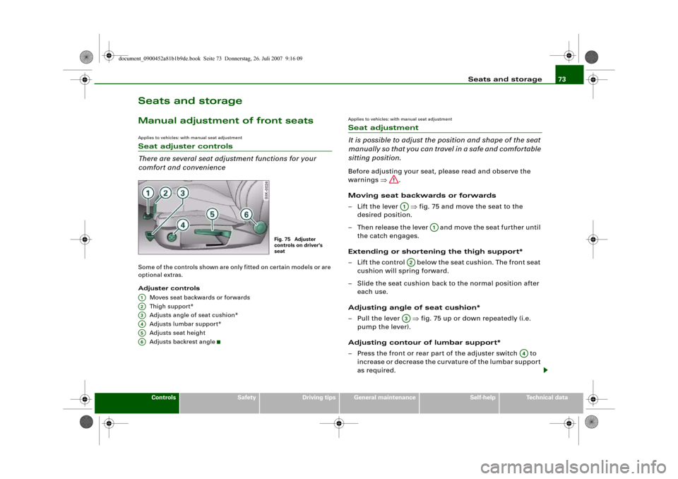
There are several seat adjustment functions for your
comfort and convenienceSome of the controls shown are only fitted on certain models or are
optional extras.
Adjuster controls
Moves seat backwards or forwards
Thigh suppor t*
Adjusts angle of seat cushion*
Adjusts lumbar support*
Adjusts seat height
Adjusts backrest angle
Applies to vehicles: with manual seat adjustmentSeat adjustment
It is possible to adjust the position and shape of the seat
manually so that you can travel in a safe and comfortable
sitting position.Before adjusting your seat, please read and observe the
warnings ⇒.
Moving seat backwards or forwards
– Lift the lever ⇒fig. 75 and move the seat to the
desired position.
– Then release the lever and move the seat further until
the catch engages.
Extending or shortening the thigh support*
– Lift the control below the seat cushion. The front seat
cushion will spring forward.
– Slide the seat cushion back to the normal position after
each use.
Adjusting angle of seat cushion*
– Pull the lever ⇒fig. 75 up or down repeatedly (i.e.
pump the lever).
Adjusting contour of lumbar support*
– Press the front or rear part of the adjuster switch to
increase or decrease the curvature of the lumbar support
as required.
Fig. 75 Adjuster
controls on driver's
seat
A1A2A3A4A5A6
A1
A1
A2A3
A4
document_0900452a81b1b9de.book Seite 73 Donnerstag, 26. Juli 2007 9:16 09
Page 77 of 342
Seats and storage75
Controls
Safety
Driving tips
General maintenance
Self-help
Technical data
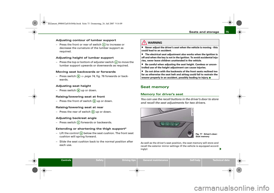
Adjusting contour of lumbar support
– Press the front or rear of switch to increase or
decrease the curvature of the lumbar support as
required.
Adjusting height of lumbar support
– Press the top or bottom of adjuster switch to move the
lumbar support upwards or downwards as required.
Moving seat backwards or forwards
– Press switch ⇒page 74, fig. 76 forwards or back-
wards.
Adjusting seat height
– Press switch up or down.
Raising/lowering seat at front
– Press the front of switch up or down.
Raising/lowering seat at rear
– Press the rear of switch up or down.
Adjusting backrest angle
– Press switch forwards or backwards.
Extending or shortening the thigh support*
– Lift the control below the seat cushion. The front seat
cushion will spring forward.
– Slide the seat cushion back to the normal position after
each use.
WARNING
•
Never adjust the driver's seat when the vehicle is moving - this
could lead to an accident.
•
The electrical seat adjustment also works when the ignition is
off and when the key is not in the ignition. To avoid accidental inju-
ries, never leave children unattended in the vehicle.
•
Be careful when adjusting the seat height. Careless or uncon-
trolled use of the height adjustment can cause injuries.
•
Do not drive with the backrests of the front seats reclined too
far as otherwise the seat belt and airbag could fail to restrain the
wearer properly in an accident, possibly leading to injury.
Seat memoryMemory for driver's seat
You can use the recall buttons in the driver's door to store
and recall the seat adjustments for two drivers.As well as the driver's seat position, the seat memory will store and
recall the exterior mirror settings (if the vehicle is equipped accord-
ingly):
AA
AA
ABAB
ABAB
ACAD
Fig. 77 Driver's door:
Seat memory
document_0900452a81b1b9de.book Seite 75 Donnerstag, 26. Juli 2007 9:16 09
Page 79 of 342
Seats and storage77
Controls
Safety
Driving tips
General maintenance
Self-help
Technical data
Applies to vehicles: with seat memoryActivating memory for remote control key
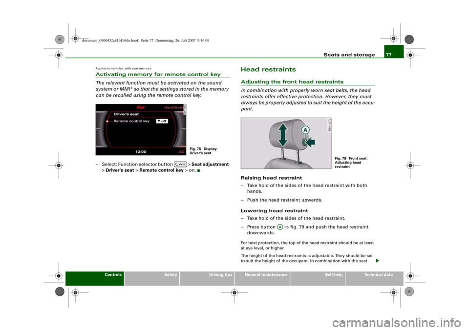
The relevant function must be activated on the sound
system or MMI* so that the settings stored in the memory
can be recalled using the remote control key.– Select: Function selector button > Seat adjustment
> Driver's seat > Remote control key > on.
Head restraintsAdjusting the front head restraints
In combination with properly worn seat belts, the head
restraints offer effective protection. However, they must
always be properly adjusted to suit the height of the occu-
pant.Raising head restraint
– Take hold of the sides of the head restraint with both
hands.
– Push the head restraint upwards.
Lowering head restraint
– Take hold of the sides of the head restraint.
– Press button ⇒fig. 79 and push the head restraint
downwards.For best protection, the top of the head restraint should be at least
at eye level, or higher.
The height of the head restraints is adjustable. They should be set
to suit the height of the occupant. In combination with the seat
Fig. 78 Display:
Driver's seat
CAR
Fig. 79 Front seat:
Adjusting head
restraint
AA
document_0900452a81b1b9de.book Seite 77 Donnerstag, 26. Juli 2007 9:16 09
Page 81 of 342
Seats and storage79
Controls
Safety
Driving tips
General maintenance
Self-help
Technical data
Luggage compar tmentLoading the luggage compartment
Loads in the luggage compartment should be safely
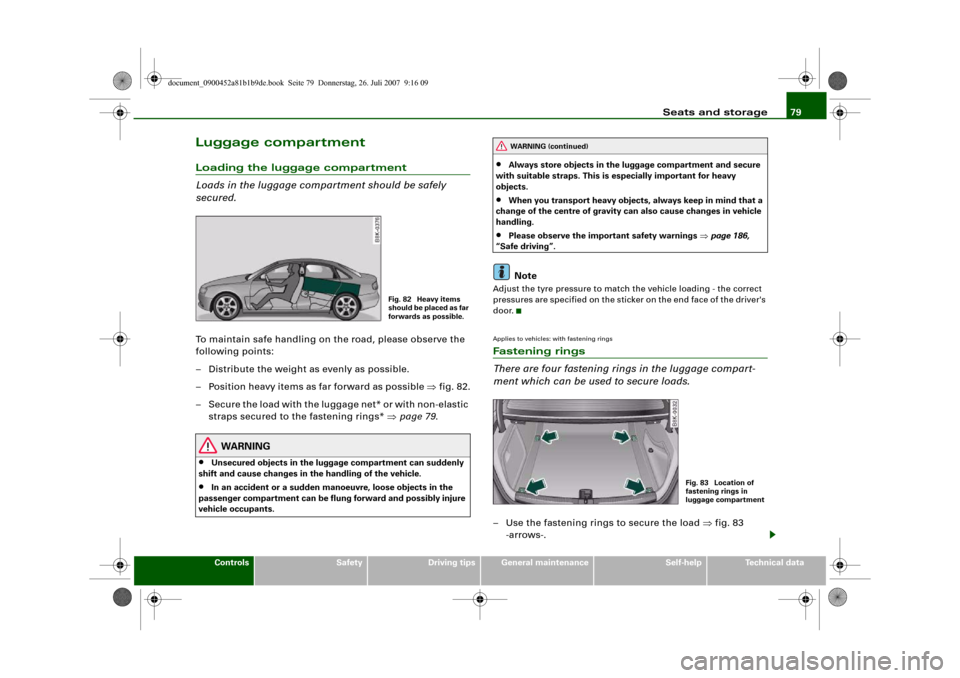
secured.To maintain safe handling on the road, please observe the
following points:
– Distribute the weight as evenly as possible.
– Position heavy items as far forward as possible ⇒fig. 82.
– Secure the load with the luggage net* or with non-elastic
straps secured to the fastening rings* ⇒page 79.
WARNING
•
Unsecured objects in the luggage compartment can suddenly
shift and cause changes in the handling of the vehicle.
•
In an accident or a sudden manoeuvre, loose objects in the
passenger compartment can be flung forward and possibly injure
vehicle occupants.
•
Always store objects in the luggage compartment and secure
with suitable straps. This is especially important for heavy
objects.
•
When you transport heavy objects, always keep in mind that a
change of the centre of gravity can also cause changes in vehicle
handling.
•
Please observe the important safety warnings ⇒page 186,
“Safe driving”.Note
Adjust the tyre pressure to match the vehicle loading - the correct
pressures are specified on the sticker on the end face of the driver's
door.Applies to vehicles: with fastening ringsFastening rings
There are four fastening rings in the luggage compart-
ment which can be used to secure loads.– Use the fastening rings to secure the load ⇒fig. 83
-arrows-.
Fig. 82 Heavy items
s h o u l d b e p l a c e d a s fa r
forwards as possible.
WARNING (continued)
Fig. 83 Location of
fastening rings in
luggage compartment
document_0900452a81b1b9de.book Seite 79 Donnerstag, 26. Juli 2007 9:16 09