2008 AUDI A4 technical data
[x] Cancel search: technical dataPage 19 of 342
Instruments and warning/indicator lamps17
Controls
Safety
Driving tips
General maintenance
Self-help
Technical data
Note
•
If the glow plug indicator lamp should start flashing while the
vehicle is moving, this indicates a fault in the engine management
system. The engine should be serviced without delay.
•
If the indicator lamp fails to light up when the ignition is
switched on, this can mean that the glow plug system is defective.
The engine should be serviced.
Electronic stabilisation program (ESP)
This warning lamp monitors the electronic stabilisation
program.The warning lamp
has the following functions:
•
It flashes when the ESP or traction control system (ASR) inter-
venes while the vehicle is in motion.
•
The warning lamp will light up continuously if the ESP or the
traction control system (ASR) has been switched off using the ESP
OFF button ⇒page 222.
•
It lights up when the ignition is switched on and should go out
again after about 2 seconds. This signals that the lamp is working
properly.
•
It will light up continuously if there is a malfunction in the ESP.
•
It will also come on if a fault should occur in the ABS because the
ESP operates in conjunction with the ABS.
If the battery has been disconnected, if the battery voltage is very
low, or if the engine has been started from an outside power source,
the ESP system will perform an initialisation of the various on-board
sensors while you drive the first few metres. The warning lamp will
light up during this period. It will go out when the initialisation has
been completed.
If the warning lamp lights up and stays on after the engine is
started, this may mean that the control system has temporarily
switched off the ESP. In this case the ESP can be reactivated by switching the ignition off and then on again. If the warning lamp
goes out, this means the system is fully functional.
For further information on the ESP ⇒page 222.
Airbag system
This warning lamp monitors the airbag and seat belt
tensioner system.The warning lamp
should light up for a few seconds when the
ignition is switched on.
If the warning lamp does not go out, or if it lights up, flashes or
flickers when the vehicle is moving, this indicates a malfunction in
the system. This is also the case if the warning lamp does not light
up when the ignition is switched on.
WARNING
If a malfunction should occur, have the system checked immedi-
ately by a qualified workshop. If this is neglected, there is a risk
that the airbag system and/or belt tensioners may not be acti-
vated in an accident.Tyre pressure monitoring
The tyre pressure should be corrected as soon as possible
if it is too low.If the
symbol flashes for about a minute and then remains lit after
you switch on the ignition, there is a fault in the system. Please
contact the nearest qualified workshop as soon as possible.
For more detailed information on the tyre pressure monitoring
system, please refer to ⇒page 39.
document_0900452a81b1b9de.book Seite 17 Donnerstag, 26. Juli 2007 9:16 09
Page 21 of 342
Instruments and warning/indicator lamps19
Controls
Safety
Driving tips
General maintenance
Self-help
Technical data
Applies to vehicles: with cruise control systemCruise control
The indicator lamp
in the instrument cluster lights up when the
cruise control system is operating.
Anti-lock brake system (ABS)
The warning lamp monitors the ABS and the electronic
differential lock (EDL).The warning lamp
lights up for a few seconds when the ignition
is switched on and while the engine is being started. The lamp goes
out again once the system has run through an automatic test
sequence.
There is a fault in the ABS if:
•
the warning lamp
does not light up when the ignition is
switched on,
•
the warning lamp does not go out again after a few seconds,
•
the warning lamp lights up when the vehicle is moving.
The vehicle can still be braked in the normal way (except that the
ABS control function is out of action). Please take the vehicle to a
qualified workshop as soon as possible. For further information on
the ABS ⇒page 222.
If a fault occurs in the ABS, the ESP warning lamp will also light up.
Fault in the main brake system
If the ABS warning lamp
lights up together with the brake
warning lamp
⇒page 32, this indicates a fault in the ABS func-
tion, and possibly a malfunction in the main brake system as well
⇒.
If there is a malfunction in the brake system the symbol
will light
up in the instrument cluster. Please refer to ⇒page 32.Fault on the electronic differential lock (EDL)
The EDL works in conjunction with the ABS. If a malfunction should
occur in the EDL, this is indicated by the ABS warning lamp
.
Please take the vehicle to a qualified workshop as soon as possible.
For further information on the EDL ⇒page 222.
WARNING
•
Before opening the bonnet and checking the brake fluid level,
observe the warning information on ⇒page 255, “Working on
components in the engine compartment”.
•
If the brake warning lamp
should light up together with the
ABS warning lamp
, stop the vehicle immediately and check the
brake fluid level in the reservoir. If the fluid level has dropped
below the "MIN" mark you must not drive on - otherwise there may
be an increased accident risk. You should obtain professional
assistance.
•
If the brake fluid level is OK, the fault in the brake system may
have been caused by a failure of the ABS control function. As a
result the rear wheels can lock relatively easily when braking. This
could cause the tail of the vehicle to skid sideways. Drive carefully
to the nearest qualified workshop and have the fault rectified.
Applies to vehicles: with Audi hold assistAudi hold assist
This warning lamp monitors the Audi hold assist function.Audi hold assist helps the driver to keep the vehicle stationary while
the engine is running, for instance on steep gradients, at traffic
lights or in stop-and-go traffic. When the Audi hold assist function
is on, you don't have to keep your foot on the brake to prevent the
vehicle from accidentally rolling away. Once it detects that the
vehicle is stopped, Audi hold assist keeps the vehicle stationary. The
green symbol
in the instrument cluster indicates that the func-
tion is activated. You can now take your foot off the brake pedal.
document_0900452a81b1b9de.book Seite 19 Donnerstag, 26. Juli 2007 9:16 09
Page 23 of 342
Driver information system21
Controls
Safety
Driving tips
General maintenance
Self-help
Technical data
Driver information systemIntroductionGeneral notes
The driver information system in the instrument cluster
shows you the status of various on-board systems at a
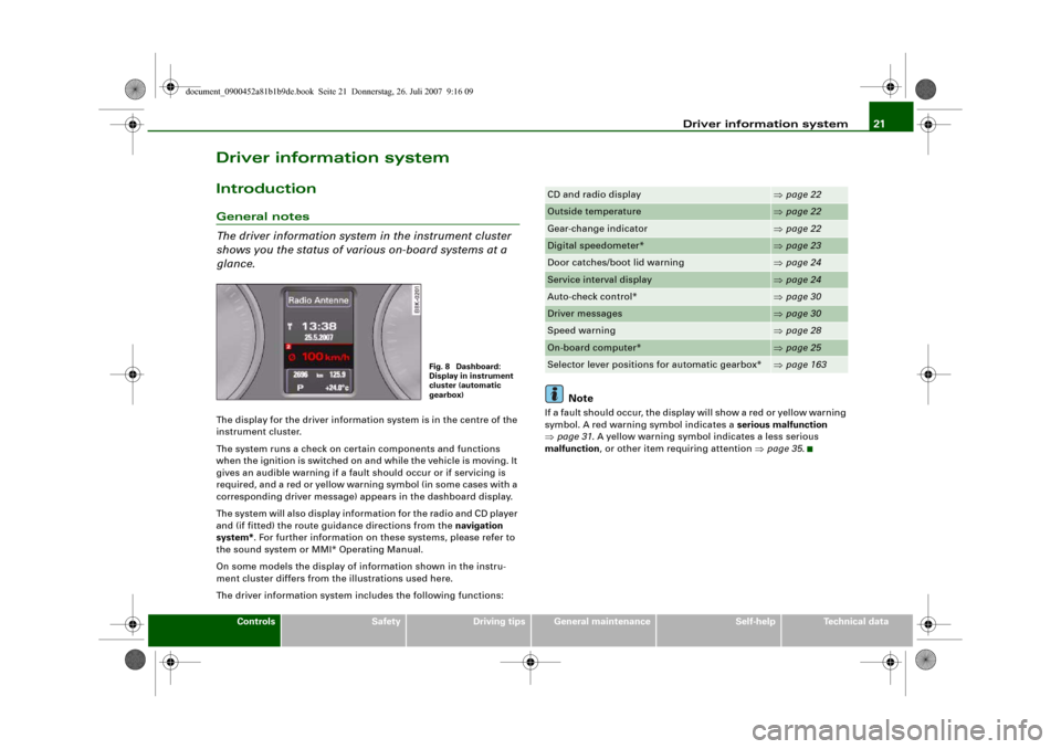
glance.The display for the driver information system is in the centre of the
instrument cluster.
The system runs a check on certain components and functions
when the ignition is switched on and while the vehicle is moving. It
gives an audible warning if a fault should occur or if servicing is
required, and a red or yellow warning symbol (in some cases with a
corresponding driver message) appears in the dashboard display.
The system will also display information for the radio and CD player
and (if fitted) the route guidance directions from the navigation
system*. For further information on these systems, please refer to
the sound system or MMI* Operating Manual.
On some models the display of information shown in the instru-
ment cluster differs from the illustrations used here.
The driver information system includes the following functions:
Note
If a fault should occur, the display will show a red or yellow warning
symbol. A red warning symbol indicates a serious malfunction
⇒page 31. A yellow warning symbol indicates a less serious
malfunction, or other item requiring attention ⇒page 35.
Fig. 8 Dashboard:
Display in instrument
cluster (automatic
gearbox)
CD and radio display
⇒page 22
Outside temperature
⇒page 22
Gear-change indicator
⇒page 22
Digital speedometer*
⇒page 23
Door catches/boot lid warning
⇒page 24
Service interval display
⇒page 24
Auto-check control*
⇒page 30
Driver messages
⇒page 30
Speed warning
⇒page 28
On-board computer*
⇒page 25
Selector lever positions for automatic gearbox*
⇒page 163
document_0900452a81b1b9de.book Seite 21 Donnerstag, 26. Juli 2007 9:16 09
Page 25 of 342
Driver information system23
Controls
Safety
Driving tips
General maintenance
Self-help
Technical data
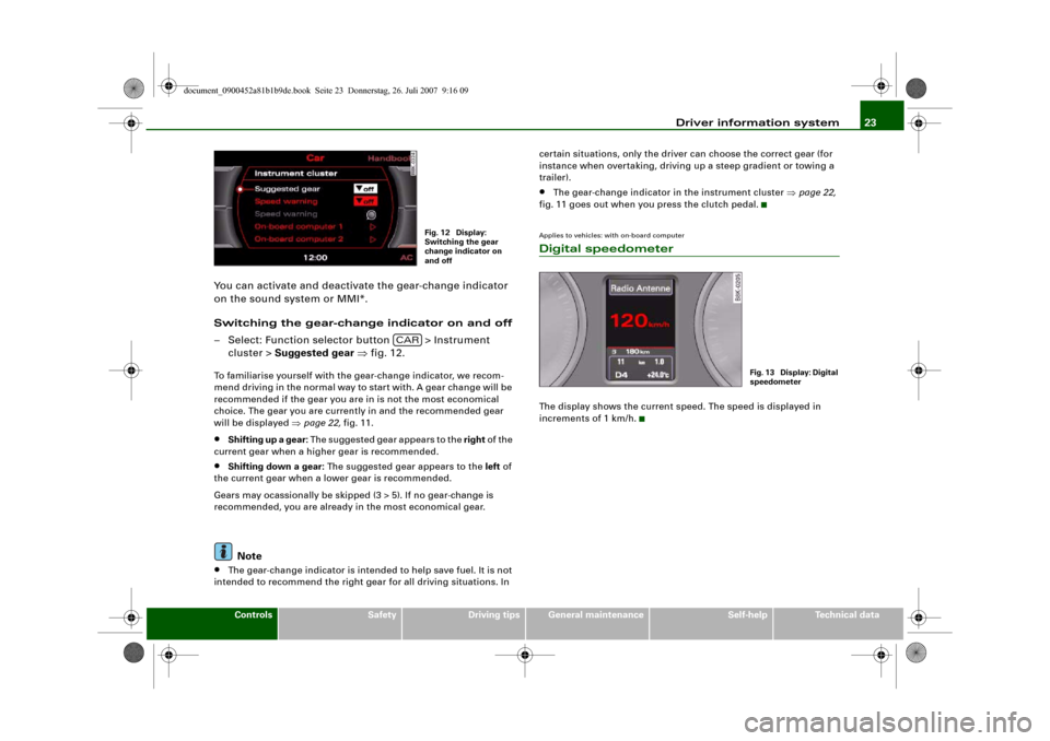
You can activate and deactivate the gear-change indicator
on the sound system or MMI*.
Switching the gear-change indicator on and off
– Select: Function selector button > Instrument
cluster > Suggested gear ⇒fig. 12.To familiarise yourself with the gear-change indicator, we recom-
mend driving in the normal way to start with. A gear change will be
recommended if the gear you are in is not the most economical
choice. The gear you are currently in and the recommended gear
will be displayed ⇒page 22, fig. 11.•
Shifting up a gear: The suggested gear appears to the right of the
current gear when a higher gear is recommended.
•
Shifting down a gear: The suggested gear appears to the left of
the current gear when a lower gear is recommended.
Gears may ocassionally be skipped (3 > 5). If no gear-change is
recommended, you are already in the most economical gear.Note
•
The gear-change indicator is intended to help save fuel. It is not
intended to recommend the right gear for all driving situations. In certain situations, only the driver can choose the correct gear (for
instance when overtaking, driving up a steep gradient or towing a
trailer).
•
The gear-change indicator in the instrument cluster ⇒page 22,
fig. 11 goes out when you press the clutch pedal.
Applies to vehicles: with on-board computerDigital speedometerThe display shows the current speed. The speed is displayed in
increments of 1 km/h.
Fig. 12 Display:
Switching the gear
change indicator on
and off
CAR
Fig. 13 Display: Digital
speedometer
document_0900452a81b1b9de.book Seite 23 Donnerstag, 26. Juli 2007 9:16 09
Page 27 of 342
Driver information system25
Controls
Safety
Driving tips
General maintenance
Self-help
Technical data the number of kilometres reaches zero, even if the estimated period
has not yet expired. The remaining distance and time are updated
and displayed briefly each time you switch on the ignition.
•
Service due: When a service is due, Service due! will appear in
the display as soon as you switch on the ignition. The display reverts
back to the standard display after a short time. In addition, a tone
will sound.
Displaying distance and time to next service
In the Car menu, you can look up the distance and time remaining
until the next oil change and next service inspection. To do this,
select function selector button > Service interval display
⇒page 24, fig. 16.
The display may not be complete on new vehicles within the first
500 km.
Resetting the service interval display
Your Audi dealer resets the display after each service. You can only
reset the oil change display yourself. To do this, select function
selector button > Service interval display > Reset oil change
interval. The next oil change will be indicated as being due
15,000 km or one year (fixed service interval) after the oil change
interval is reset.Caution
The system cannot calculate the figures for the service indicator if
the battery is disconnected from the vehicle, so no service reminder
can be displayed during this time. Please remember that keeping to
the correct service intervals is most important for the service life
and residual value of the vehicle (and especially for the life of the
engine). The period between two services must never be longer
than the time specified in the Service Schedule, even if you only
cover a low mileage during this time.
Note
•
Do not reset the display between oil changes - otherwise the
display will be incorrect.
•
The information in the service interval display remains intact if
the battery is disconnected.
•
The distance to the next service cannot be called up if the system
has detected a Priority 1 fault (red symbol).
•
If the service was not performed by a qualified workshop, the oil
change interval display can only be set to “fixed service intervals” of
15,000 km. If you wish to continue with the “LongLife” service, you
will need to have the oil change interval display reset by a qualified
workshop.
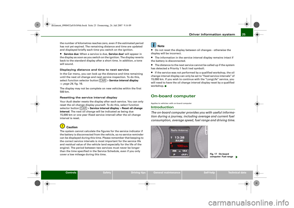
On-board computerApplies to vehicles: with on-board computerIntroduction
The on-board computer provides you with useful informa-
tion during a journey, including average and current fuel
consumption, average speed, fuel range and driving time.
CAR
CAR
Fig. 17 On-board
computer: Fuel range
document_0900452a81b1b9de.book Seite 25 Donnerstag, 26. Juli 2007 9:16 09
Page 29 of 342
Driver information system27
Controls
Safety
Driving tips
General maintenance
Self-help
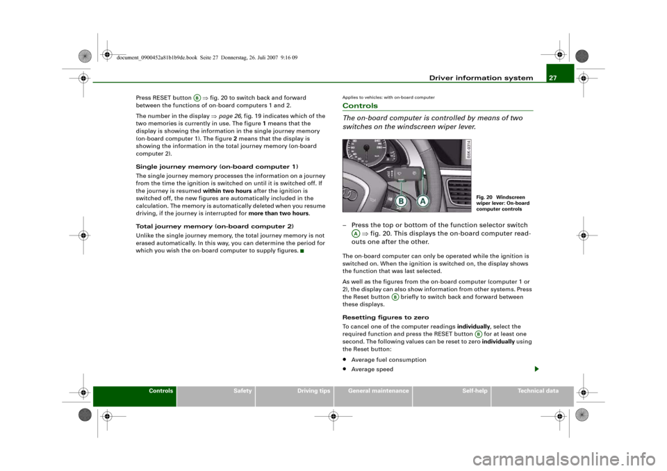
Technical data Press RESET button ⇒fig. 20 to switch back and forward
between the functions of on-board computers 1 and 2.
The number in the display ⇒page 26, fig. 19 indicates which of the
two memories is currently in use. The figure 1 means that the
display is showing the information in the single journey memory
(on-board computer 1). The figure 2 means that the display is
showing the information in the total journey memory (on-board
computer 2).
Single journey memory (on-board computer 1)
The single journey memory processes the information on a journey
from the time the ignition is switched on until it is switched off. If
the journey is resumed within two hours after the ignition is
switched off, the new figures are automatically included in the
calculation. The memory is automatically deleted when you resume
driving, if the journey is interrupted for more than two hours.
Total journey memory (on-board computer 2)
Unlike the single journey memory, the total journey memory is not
erased automatically. In this way, you can determine the period for
which you wish the on-board computer to supply figures.
Applies to vehicles: with on-board computerControls
The on-board computer is controlled by means of two
switches on the windscreen wiper lever.– Press the top or bottom of the function selector switch
⇒fig. 20. This displays the on-board computer read-
outs one after the other.The on-board computer can only be operated while the ignition is
switched on. When the ignition is switched on, the display shows
the function that was last selected.
As well as the figures from the on-board computer (computer 1 or
2), the display can also show information from other systems. Press
the Reset button briefly to switch back and forward between
these displays.
Resetting figures to zero
To cancel one of the computer readings individually, select the
required function and press the RESET button for at least one
second. The following values can be reset to zero individually using
the Reset button:•
Average fuel consumption
•
Average speed
AB
Fig. 20 Windscreen
wiper lever: On-board
computer controls
AA
AB
AB
document_0900452a81b1b9de.book Seite 27 Donnerstag, 26. Juli 2007 9:16 09
Page 31 of 342
Driver information system29
Controls
Safety
Driving tips
General maintenance
Self-help
Technical data need to keep below a particular speed when winter tyres are fitted,
etc.
The speed limit warning symbol
for speed warning 2 will appear
in the display if you exceed the pre-set speed. Unlike speed limit
warning 1, the warning symbol only goes out once the road speed
has dropped below the stored value again.
Setting speed limit warning 2 ⇒page 29.
Note
Please bear in mind that, even with the speed warning function, it is
still important to keep a check on the car's speed with the speedom-
eter and to observe the statutory speed limits.Applies to vehicles: with speed warning functionSetting speed limit warning 1
You can use the button to set, alter or cancel speed
limit warning 1.Selecting speed limit
– Drive at the desired maximum speed.
– Press the button in the instrument cluster ⇒fig. 22
for one second.Clearing speed limit
– Drive the vehicle at a minimum of 5 km/h.
– Press the button for at least 2 seconds.
The speed warning symbol
lights up briefly in the display to
confirm that the selected speed has been stored. The speed limit
that has been set remains stored until another speed is set with a
brief push of the button, or until the memory is cleared with a long
push of the button.
When the speed limit has been cleared, the display will show a
crossed-out warning symbol .
Applies to vehicles: with speed warning functionSetting speed limit warning 2
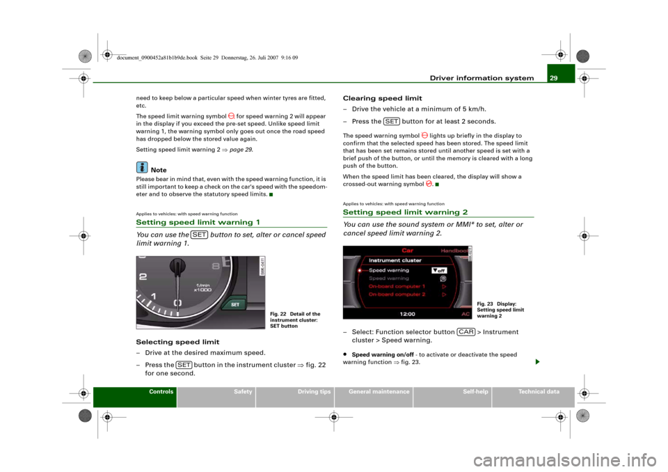
You can use the sound system or MMI* to set, alter or
cancel speed limit warning 2.– Select: Function selector button > Instrument
cluster > Speed warning.•
Speed warning on/off - to activate or deactivate the speed
warning function ⇒fig. 23.
SET
Fig. 22 Detail of the
instrument cluster:
SET button
SET
SET
Fig. 23 Display:
Setting speed limit
warning 2
CAR
document_0900452a81b1b9de.book Seite 29 Donnerstag, 26. Juli 2007 9:16 09
Page 33 of 342
Driver information system31
Controls
Safety
Driving tips
General maintenance
Self-help
Technical data For example, in the event of an oil pressure malfunction the oil pres-
sure symbol
will appear in the display. In addition, the following
message will appear:
Switch off engine and check oil level
The message will disappear from the display after about 5 seconds.
If required, the message can be called up again by briefly pressing
the button ⇒page 30, fig. 24.
Driver messages and yellow symbols
If a yellow warning symbol appears in the display, it will automati-
cally be accompanied by the corresponding driver message.
For example, if the symbol
appears (windscreen washer fluid
low), the display will also show the message:
Please top up washer fluid
The message will disappear after a few seconds. If required, the
message can be called up again by briefly pressing the
button.
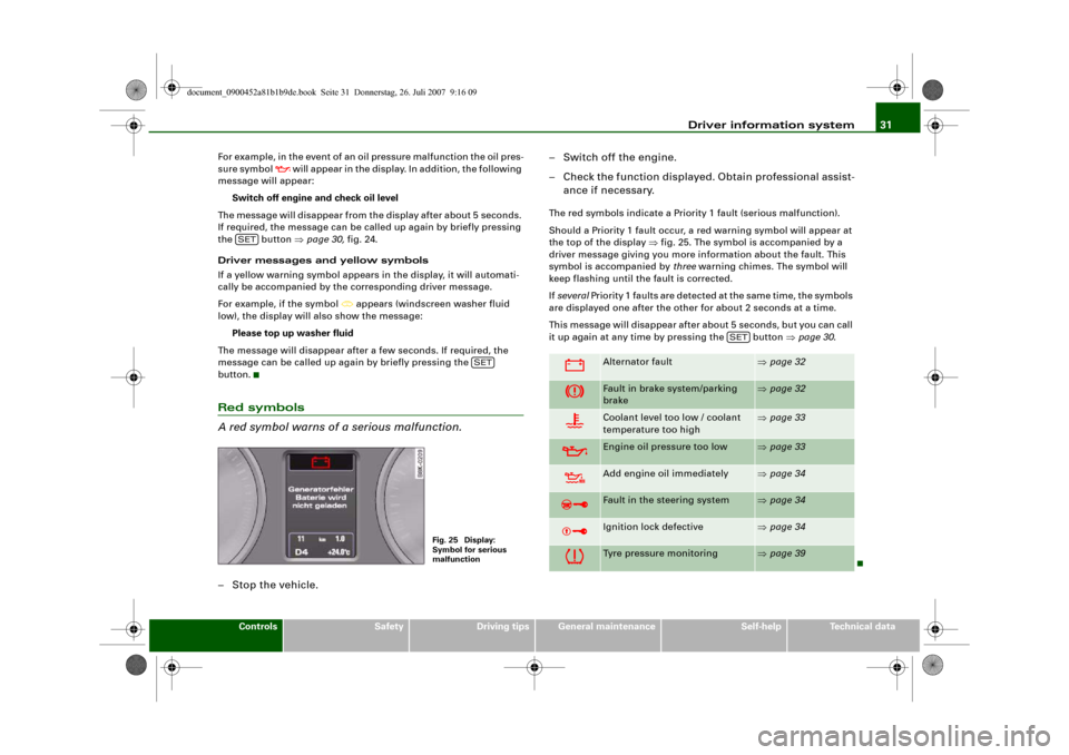
Red symbols
A red symbol warns of a serious malfunction.–Stop the vehicle.– Switch off the engine.
– Check the function displayed. Obtain professional assist-
ance if necessary.
The red symbols indicate a Priority 1 fault (serious malfunction).
Should a Priority 1 fault occur, a red warning symbol will appear at
the top of the display ⇒fig. 25. The symbol is accompanied by a
driver message giving you more information about the fault. This
symbol is accompanied by three warning chimes. The symbol will
keep flashing until the fault is corrected.
If several Priority 1 faults are detected at the same time, the symbols
are displayed one after the other for about 2 seconds at a time.
This message will disappear after about 5 seconds, but you can call
it up again at any time by pressing the button ⇒page 30.
SET
SET
Fig. 25 Display:
Symbol for serious
malfunction
Alternator fault
⇒page 32
Fault in brake system/parking
brake
⇒page 32
Coolant level too low / coolant
temperature too high
⇒page 33
Engine oil pressure too low
⇒page 33
Add engine oil immediately
⇒page 34
Fault in the steering system
⇒page 34
Ignition lock defective
⇒page 34
Tyre pressure monitoring
⇒page 39
SET
document_0900452a81b1b9de.book Seite 31 Donnerstag, 26. Juli 2007 9:16 09