2008 AUDI A4 change wheel
[x] Cancel search: change wheelPage 290 of 342
Self-help 288•
Seek professional assistance if the repair of a tyre puncture is
not possible with the sealing compound.
•
If tyre pressure is less than 1.3 bar after driving about 10
minutes, the tyre is too badly damaged. Do not drive on. You
should obtain professional assistance.Caution
Take special care if you have to repair a tyre on a gradient.
Note
•
Do not use the compressor for longer than 6 minutes at a time,
as it could overheat. When the compressor has cooled down, you
can use it again.
•
If tyre sealant should leak out, leave it to dry and then pull it off
like foil.
•
After carrying out a tyre repair remember to buy a new tyre
sealant can at a qualified workshop. This will ensure that the Tyre
Mobility System is operative again.
•
Please observe the relevant regulations.
Changing a wheelPreparations
Some preparations are necessary before changing a
wheel.– If you have a flat tyre, stop the car well away from moving
traffic. Choose a location that is as level as possible.– All passengers should leave the car. They should wait in
a safe place (for instance behind the roadside crash
barrier).
– Apply the parking brake to stop the vehicle moving acci-
dentally.
–Engage first gear (manual gearbox) or move selector
lever to position P (automatic gearbox).
– When towing a trailer: unhitch the trailer from your
vehicle.
– Take the tools ⇒page 283 and the spare wheel*
⇒page 284 out of the luggage compartment.
WARNING
If you have a puncture in moving traffic, switch on the hazard
warning lights and place the warning triangle in a visible location.
This is for your own safety and also warns other road users.
Caution
If you have to change the tyre on a gradient, block the wheel oppo-
site the wheel being changed by placing a stone or similar object
under it to prevent the vehicle from rolling away.
Note
Please observe the relevant regulations.How to change a wheel
Change the wheel as described below.–Pull off the hub cap. Also refer to ⇒page 289, “Hub
caps”.
WARNING (continued)
document_0900452a81b1b9de.book Seite 288 Donnerstag, 26. Juli 2007 9:16 09
Page 292 of 342
Self-help 290
Loosening
–Fit the box spanner as far as it will go over the wheel
bolt
5).
– Grip the box spanner as close to the end as possible and
turn the wheel bolts about one turn anti-clockwise
⇒page 289, fig. 272 -arrow-.
Tightening
– Fit the box spanner as far as it will go over the wheel
bolt5).
– Grip the box spanner as close to the end as possible and
tighten the bolt firmly by turning clockwise.
WARNING
To avoid accidents, the wheel bolts should only be loosened
slightly (about one turn) before raising the vehicle with the jack*.
Note
•
Do not use the hexagonal socket in the screwdriver handle to
loosen or tighten the wheel bolts.
•
If the wheel bolt is very tight, it may be possible to loosen it by
pushing down the end of the spanner carefully with your foot. Hold
on to the car for support and take care not to slip.
Raising the vehicle
The vehicle must be raised with the jack* to remove the
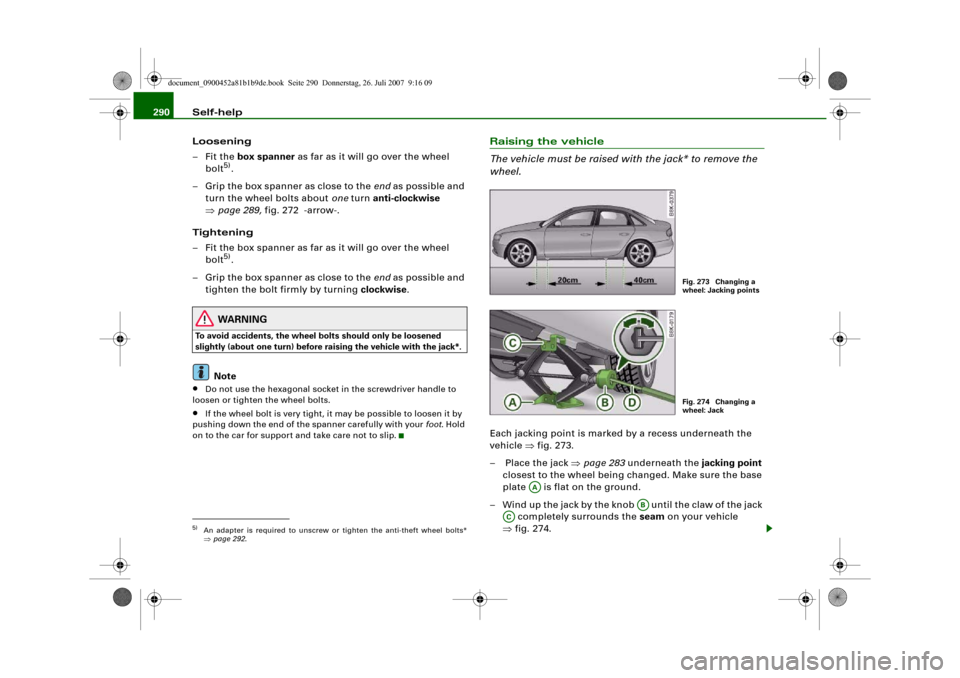
wheel.Each jacking point is marked by a recess underneath the
vehicle ⇒fig. 273.
– Place the jack ⇒page 283 underneath the jacking point
closest to the wheel being changed. Make sure the base
plate is flat on the ground.
– Wind up the jack by the knob until the claw of the jack
completely surrounds the seam on your vehicle
⇒fig. 274.
5)An adapter is required to unscrew or tighten the anti-theft wheel bolts*
⇒page 292.
Fig. 273 Changing a
wheel: Jacking pointsFig. 274 Changing a
wheel: Jack
AA
AB
AC
document_0900452a81b1b9de.book Seite 290 Donnerstag, 26. Juli 2007 9:16 09
Page 293 of 342
Self-help291
Controls
Safety
Driving tips
General maintenance
Self-help
Technical data
– Now fit the crank handle onto the jack by inserting it
in the opening on the knob ⇒page 290, fig. 274. Turn the
crank handle clockwise or anti-clockwise to secure it in
place.
– Raise the vehicle by winding the crank handle until the
defective wheel is clear of the ground.Recesses at the front and rear of the door sills mark the jacking
points ⇒page 290, fig. 273. There is one jacking point for each
wheel. The distance from the jacking points to the wheel arches is
approximately 20 cm at the front and 40 cm at the rear. The jack may
only be applied at the seam of the jacking points shown.
An unstable surface under the jack may cause the vehicle to slip off
the jack. Always provide a firm base for the jack on the ground. If
necessary use a large, strong board or similar support. On a hard,
slippery surface (such as tiles) use a rubber mat or similar to prevent
the jack from slipping.
WARNING
•
Prevent the base of the jack from slipping – risk of injury.
•
The car can be damaged if the jack is not applied at the correct
jacking points. There is also a risk of injury since the jack can slip
off suddenly if it is not properly engaged.
Taking off the wheel and putting on the spare wheel
Step-by-step instructions for taking off the wheel and
putting on the spare wheel.Change the wheel as described below after loosening the
wheel bolts and raising the vehicle with the jack*.
Taking off the wheel
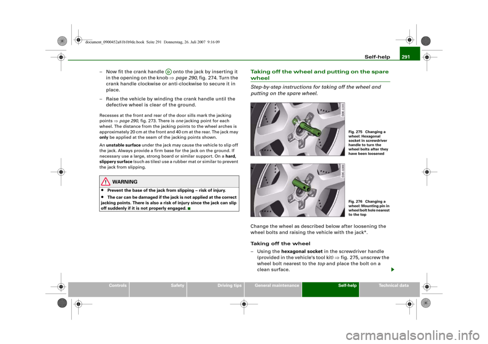
–Using the hexagonal socket in the screwdriver handle
(provided in the vehicle's tool kit) ⇒fig. 275, unscrew the
wheel bolt nearest to the top and place the bolt on a
clean surface.
AD
Fig. 275 Changing a
wheel: Hexagonal
socket in screwdriver
handle to turn the
wheel bolts after they
have been loosenedFig. 276 Changing a
wheel: Mounting pin in
wheel bolt hole nearest
to the top
document_0900452a81b1b9de.book Seite 291 Donnerstag, 26. Juli 2007 9:16 09
Page 294 of 342
Self-help 292
– Screw in the mounting pin (provided in the vehicle's tool
kit) by hand in place of the wheel bolt ⇒page 291,
fig. 276.
– Then unscrew the other wheel bolts as described above.
– Take off the wheel. The mounting pin stays where it is.
Putting on the spare wheel
– Put on the spare wheel, using the mounting pin to guide
it into place.
– Screw in the wheel bolts and tighten them lightly using
the hexagonal opening in the screwdriver handle.
– Then unscrew the mounting pin and tighten the
remaining wheel bolt lightly.
– Carry out the steps required after you have changed the
wheel ⇒page 289, “After changing a wheel”.The wheel bolts should be clean and turn easily. Before putting on
the spare wheel, inspect the condition of the wheel and hub
mounting surfaces. These surfaces must be clean before mounting
the wheel.
The wheel bolts are easier to remove from the wheel rim if you use
the hexagonal socket in the screwdriver handle. The reversible
screwdriver blade should be removed as a precautionary measure
when the tool is used for this purpose.
Note the direction of rotation when putting on a tyre with direc-
tional tread pattern ⇒page 292.
Note
Do not use the hexagonal socket in the screwdriver handle to loosen
or tighten the wheel bolts.
Tyres with directional tread pattern
Tyres with directional tread pattern must be mounted so
that they rotate in the correct direction.A directional tread pattern is identified by arrows on the sidewall
pointing in the forward running direction. Always note the direction
of rotation indicated when mounting the wheel. This is important so
that these tyres can give maximum grip and avoid excessive noise,
tread wear and aquaplaning.
Drive carefully should you ever have a puncture and have to mount
the spare wheel so it rotates in the wrong direction. This is because
the tyre will not give optimum performance. Bear this in mind
particularly when driving on wet roads.
To benefit from the advantages of tyres with this type of tread
pattern, the defective tyre should be replaced and refitted as soon
as possible so that all tyres again rotate in the correct direction.Applies to vehicles: with anti-theft wheel boltsAnti-theft wheel bolts
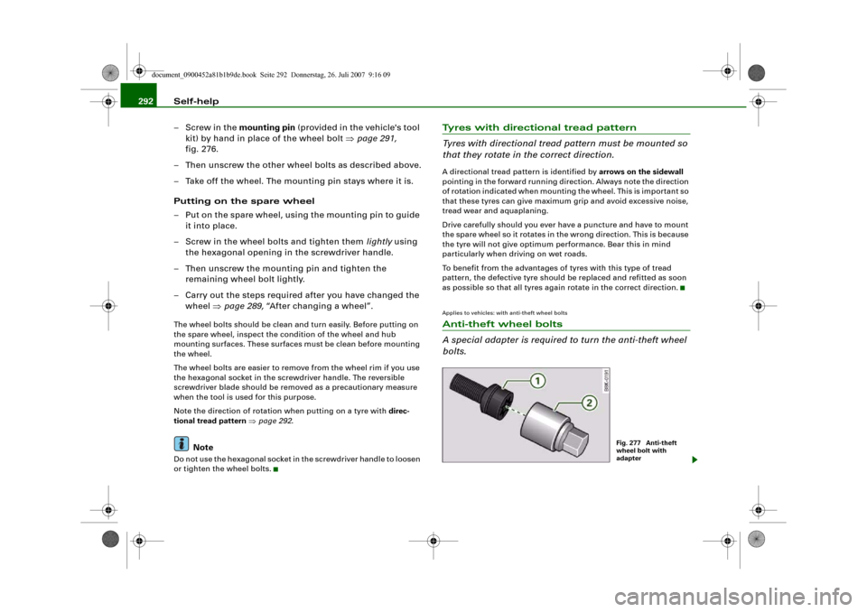
A special adapter is required to turn the anti-theft wheel
bolts.
Fig. 277 Anti-theft
wheel bolt with
adapter
document_0900452a81b1b9de.book Seite 292 Donnerstag, 26. Juli 2007 9:16 09
Page 336 of 342
Index 334
Operation . . . . . . . . . . . . . . . . . . . . . . . 121
Parking . . . . . . . . . . . . . . . . . . . . . . . . . 122
Releasing and applying . . . . . . . . . . . 121
Warning lamp . . . . . . . . . . . . . . . . . 19, 20
Electronic differential lock
How the system works . . . . . . . . . . . . 222
Warning lamp . . . . . . . . . . . . . . . . . . . . 19
Electronic immobiliser . . . . . . . . . . . . . 14, 43
Electronic stabilisation program
How the system works . . . . . . . . . . . . 222
Warning lamp . . . . . . . . . . . . . . . . . . . . 17
Emergency braking function . . . . . . . . . . 123
Emergency key . . . . . . . . . . . . . . . . . . . . . . 45
Emergency release
Ignition key . . . . . . . . . . . . . . . . . . . . . . 46
Emission control systems
Catalytic converter . . . . . . . . . . . . . . . 229
Diesel particulate filter . . . . . . . . . . . . 229
Emissions . . . . . . . . . . . . . . . . . . . . . . . . . 321
Engine compartment
Safety notes . . . . . . . . . . . . . . . . . . . . . 255
Engine compartment layout . . . . . . . . . . 256
Engine data
SeePerformance, weights and
dimensions . . . . . . . . . . . . . . . . . . . . 323
Engine hood
SeeBonnet . . . . . . . . . . . . . . . . . . . . . . 254
Engine management
(EPC) warning lamp . . . . . . . . . . . . . . . 16
Engine oil . . . . . . . . . . . . . . . . . . . . . . 34, 257
Checking oil level . . . . . . . . . . . . 258, 259
Consumption . . . . . . . . . . . . . . . . 258, 259
LongLife Service . . . . . . . . . . . . . . . . . 257Topping up . . . . . . . . . . . . . . . . . . . . . . 259
See alsoPerformance, weights and
dimensions . . . . . . . . . . . . . . . . . . . . 323
Engine oil capacity
SeePerformance, weights and
dimensions . . . . . . . . . . . . . . . . . . . . 323
Engine oil pressure
Warning lamp . . . . . . . . . . . . . . . . . . . . 33
Engine oil sensor
Malfunction . . . . . . . . . . . . . . . . . . . . . . 38
Environmental compatibility . . . . . . . . . . 231
Environmental tips
Filling the tank . . . . . . . . . . . . . . . . . . . 252
Heated rear window . . . . . . . . . . . 98, 106
Leaks . . . . . . . . . . . . . . . . . . . . . . . . . . . 255
Roof carrier . . . . . . . . . . . . . . . . . . . . . . 84
EPC
SeeEngine management . . . . . . . . . . . 16
ESP
SeeElectronic stabilisation program . 17
Ethanol fuel . . . . . . . . . . . . . . . . . . . . . . . . 251
Exterior mirrors . . . . . . . . . . . . . . . . . . . . . . 70
FFastening rings . . . . . . . . . . . . . . . . . . 79, 193
Filling the tank . . . . . . . . . . . . . . . . . . . . . 252
Releasing the tank flap manually . . . 253
Fire extinguisher . . . . . . . . . . . . . . . . . . . . 283
First-aid kit . . . . . . . . . . . . . . . . . . . . . . . . . 282
Floor mats . . . . . . . . . . . . . . . . . . . . . 191, 192
Fog lights . . . . . . . . . . . . . . . . . . . . . . . . . . . 58
Four-wheel drive . . . . . . . . . . . . . . . . . . . . 226Front passenger
SeeSitting position . . . . . . . . . . . . . . . 189
Fuel
Biodiesel . . . . . . . . . . . . . . . . . . . . . . . . 251
Capacity . . . . . . . . . . . . . . . . . . . . . . . . 321
Consumption . . . . . . . . . . . . . . . . . . . . 321
Current fuel consumption . . . . . . . . . . 25
Diesel . . . . . . . . . . . . . . . . . . . . . . . . . . 251
Ethanol . . . . . . . . . . . . . . . . . . . . . . . . . 251
Fuel level low . . . . . . . . . . . . . . . . . . . . . 37
Petrol . . . . . . . . . . . . . . . . . . . . . . . . . . 251
Saving fuel . . . . . . . . . . . . . . . . . . . . . . 229
Fuel consumption . . . . . . . . . . . . . . . . . . . 321
Fuel range . . . . . . . . . . . . . . . . . . . . . . . . . . 25
Fuel tank flap . . . . . . . . . . . . . . . . . . . . . . . 252
Fuse, changing . . . . . . . . . . . . . . . . . . . . . 300
GGarage door opener . . . . . . . . . . . . . . . . . 179
Gear-change indicator . . . . . . . . . . . . . . . . 22
Generator
SeeAlternator . . . . . . . . . . . . . . . . . . . . 32
Glove box . . . . . . . . . . . . . . . . . . . . . . . . . . . 90
Glow plug system
Indicator lamp . . . . . . . . . . . . . . . . . . . . 16HHandbrake
SeeElectro-mechanical parking brake . . .
121
document_0900452a81b1b9de.book Seite 334 Donnerstag, 26. Juli 2007 9:16 09