Page 6 of 650

IMPORTANT NOTICE
THIS MACHINE IS DESIGNED STRICTLY
FOR COMPETITION USE, ONLY ON A
CLOSED COURSE. It is illegal for this
machine to be operated on any public street,
road, or highway. Off-road use on public lands
may also be illegal. Please check local regula-
tions before riding.
1. THIS MACHINE IS TO BE OPERATED
BY AN EXPERIENCED RIDER ONLY.
Do not attempt to operate this
machine at maximum power until you
are totally familiar with its character-
istics.
2. THIS MACHINE IS DESIGNED TO BE
RIDDEN BY THE OPERATOR ONLY.
Do not carry passengers on this
machine.
3. ALWAYS WEAR PROTECTIVE
APPAREL.
When operating this machine, always
wear an approved helmet with gog-
gles or a face shield. Also wear heavy
boots, gloves, and protective cloth-
ing. Always wear proper fitting cloth-
ing that will not be caught in any of
the moving parts or controls of the
machine.
4. ALWAYS MAINTAIN YOUR MACHINE
IN PROPER WORKING ORDER.
For safety and reliability, the machine
must be properly maintained. Always
perform the pre-operation checks
indicated in this manual. Correcting a
mechanical problem before you ride
may prevent an accident.
5. GASOLINE IS HIGHLY FLAMMABLE.
Always turn off the engine while refu-
eling. Take care to not spill any gaso-
line on the engine or exhaust system.
Never refuel in the vicinity of an open
flame, or while smoking.
SAFETY INFORMATION
Page 20 of 650

EC0A0000
CONTENTS
CHAPTER 1
GENERAL INFORMATION
DESCRIPTION ...........................................1-1
MACHINE IDENTIFICATION .....................1-2
IMPORTANT INFORMATION ....................1-3
CHECKING OF CONNECTION .................1-6
SPECIAL TOOLS ......................................1-7
CONTROL FUNCTIONS ..........................1-10
FUEL ........................................................1-13
STARTING AND BREAK-IN ....................1-14
TORQUE-CHECK POINTS ......................1-18
CLEANING AND STORAGE ...................1-19
CHAPTER 2
SPECIFICATIONS
GENERAL SPECIFICATIONS ...................2-1
MAINTENANCE SPECIFICATIONS ..........2-4
GENERAL TORQUE
SPECIFICATIONS ...................................2-18
DEFINITION OF UNITS ...........................2-18
LUBRICATION DIAGRAMS ....................2-19
CABLE ROUTING DIAGRAM .................2-21
CHAPTER 3
REGULAR INSPECTION AND
ADJUSTMENTS
MAINTENANCE INTERVALS ...................3-1
PRE-OPERATION INSPECTION
AND MAINTENANCE ................................3-4
ENGINE ......................................................3-5
CHASSIS .................................................3-24
ELECTRICAL ...........................................3-46
Page 36 of 650
1 - 6
GEN
INFO
CHECKING OF CONNECTION
EC1C0001
CHECKING OF CONNECTION
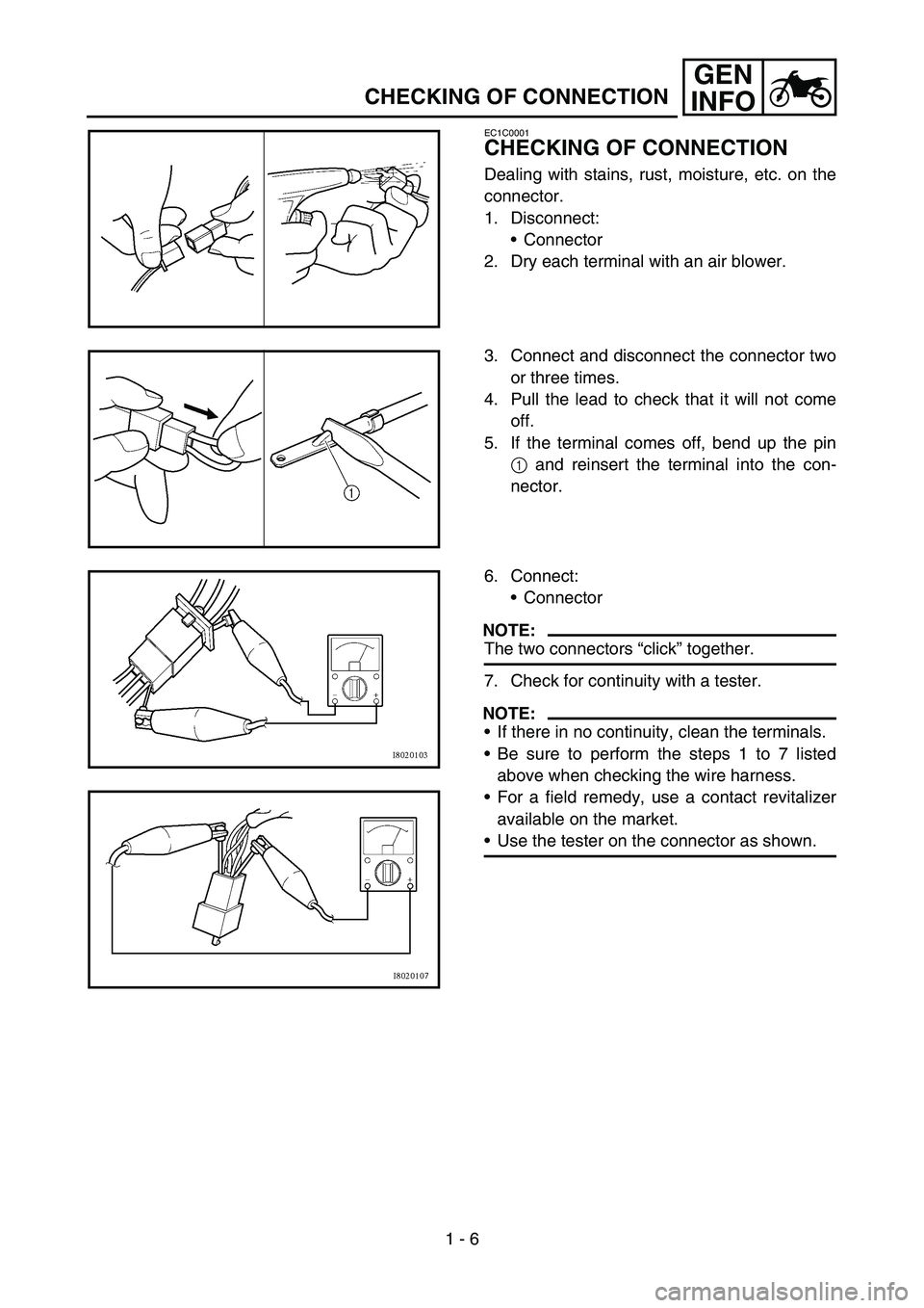
Dealing with stains, rust, moisture, etc. on the
connector.
1. Disconnect:
Connector
2. Dry each terminal with an air blower.
3. Connect and disconnect the connector two
or three times.
4. Pull the lead to check that it will not come
off.
5. If the terminal comes off, bend up the pin
1 and reinsert the terminal into the con-
nector.
6. Connect:
Connector
NOTE:
The two connectors “click” together.
7. Check for continuity with a tester.
NOTE:
If there in no continuity, clean the terminals.
Be sure to perform the steps 1 to 7 listed
above when checking the wire harness.
For a field remedy, use a contact revitalizer
available on the market.
Use the tester on the connector as shown.
Page 38 of 650
GEN
INFO
1 - 7
SPECIAL TOOLS
EC140001
SPECIAL TOOLS
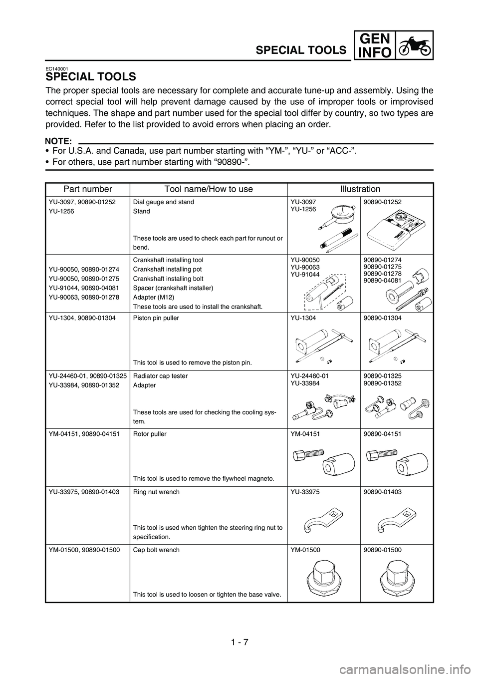
The proper special tools are necessary for complete and accurate tune-up and assembly. Using the
correct special tool will help prevent damage caused by the use of improper tools or improvised
techniques. The shape and part number used for the special tool differ by country, so two types are
provided. Refer to the list provided to avoid errors when placing an order.
NOTE:
For U.S.A. and Canada, use part number starting with “YM-”, “YU-” or “ACC-”.
For others, use part number starting with “90890-”.
Part number Tool name/How to use Illustration
YU-3097, 90890-01252
YU-1256Dial gauge and stand
Stand
These tools are used to check each part for runout or
bend.YU-3097
YU-125690890-01252
YU-90050, 90890-01274
YU-90050, 90890-01275
YU-91044, 90890-04081
YU-90063, 90890-01278Crankshaft installing tool
Crankshaft installing pot
Crankshaft installing bolt
Spacer (crankshaft installer)
Adapter (M12)
These tools are used to install the crankshaft.YU-90050
YU-90063
YU-9104490890-01274
90890-01275
90890-01278
90890-04081
YU-1304, 90890-01304 Piston pin puller
This tool is used to remove the piston pin.YU-1304 90890-01304
YU-24460-01, 90890-01325
YU-33984, 90890-01352Radiator cap tester
Adapter
These tools are used for checking the cooling sys-
tem.YU-24460-01
YU-3398490890-01325
90890-01352
YM-04151, 90890-04151 Rotor puller
This tool is used to remove the flywheel magneto.YM-04151 90890-04151
YU-33975, 90890-01403 Ring nut wrench
This tool is used when tighten the steering ring nut to
specification.YU-33975 90890-01403
YM-01500, 90890-01500 Cap bolt wrench
This tool is used to loosen or tighten the base valve.YM-01500 90890-01500
Page 39 of 650

GEN
INFO
1 - 8
SPECIAL TOOLS
YM-01501, 90890-01501 Cap bolt ring wrench
This tool is used to loosen or tighten the damper
assembly.YM-01501 90890-01501
YM-A0948, 90890-01502 Fork seal driver
This tool is used when install the fork oil seal.YM-A0948 90890-01502
YU-3112-C, 90890-03112 Pocket tester
Use this tool to inspect the coil resistance, output
voltage and amperage.YU-3112-C 90890-03112
YM-33277-A, 90890-03141 Timing light
This tool is necessary for checking ignition timing.YM-33277-A 90890-03141
YM-4019, 90890-04019 Valve spring compressor
This tool is needed to remove and install the valve
assemblies.YM-4019 90890-04019
YM-91042, 90890-04086 Clutch holding tool
This tool is used to hold the clutch when removing or
installing the clutch boss securing nut.YM-91042 90890-04086
YM-4116, 90890-04116
YM-4097, 90890-04097Valve guide remover
Intake 4.5 mm (0.18 in)
Exhaust 5.0 mm (0.20 in)
This tool is needed to remove and install the valve
guide.YM-4116
YM-409790890-04116
90890-04097
YM-4117, 90890-04117
YM-4098, 90890-04098Valve guide installer
Intake
Exhaust
This tool is needed to install the valve guide.YM-4117
YM-409890890-04117
90890-04098
YM-4118, 90890-04118
YM-4099, 90890-04099Valve guide reamer
Intake 4.5 mm (0.18 in)
Exhaust 5.0 mm (0.20 in)
This tool is needed to rebore the new valve guide.YM-4118
YM-4099 90890-04118
90890-04099
Part number Tool name/How to use Illustration
Page 40 of 650
GEN
INFO
1 - 9
SPECIAL TOOLS
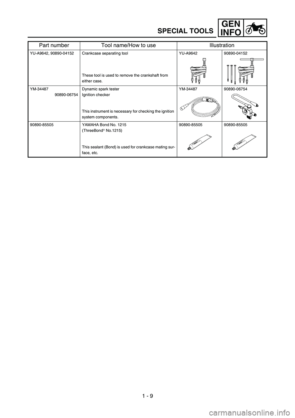
YU-A9642, 90890-04152 Crankcase separating tool
These tool is used to remove the crankshaft from
either case.YU-A9642 90890-04152
YM-34487
90890-06754Dynamic spark tester
Ignition checker
This instrument is necessary for checking the ignition
system components.YM-34487 90890-06754
90890-85505 YAMAHA Bond No. 1215
(ThreeBond
No.1215)
This sealant (Bond) is used for crankcase mating sur-
face, etc.90890-85505 90890-85505
Part number Tool name/How to use Illustration
Page 56 of 650

1 - 14
GEN
INFO
STARTING AND BREAK-IN
STARTING AND BREAK-IN
WARNING
Never start or run the engine in a closed
area. The exhaust fumes are poisonous;
they can cause loss of consciousness and
death in a very short time. Always operate
the machine in a well-ventilated area.
CAUTION:
The carburetor on this machine has a
built-in accelerator pump. Therefore,
when starting the engine, do not operate
the throttle or the spark plug will foul.
Unlike a two-stroke engine, this engine
cannot be kick started when the throttle is
open because the kick starter may kick
back. Also, if the throttle is open the air/
fuel mixture may be too lean for the
engine to start.
Before starting the machine, perform the
checks in the pre-operation check list.
STARTING A COLD ENGINE
1. Inspect the coolant level.
2. Turn the fuel cock to “ON”.
3. Shift the transmission into neutral.
4. Fully open the cold starter knob 1.
5. Kick the kick starter.
WARNING
Do not open the throttle while kicking the
kick starter. Otherwise, the kick starter may
kick back.
1
Page 62 of 650

1 - 17
GEN
INFO
BREAK-IN PROCEDURES
1. Before starting the engine, fill the fuel tank
with the fuel.
2. Perform the pre-operation checks on the
machine.
3. Start and warm up the engine. Check the
idle speed, and check the operation of the
controls and the “ENGINE STOP” button.
Then, restart the engine and check its
operation within no more than 5 minutes
after it is restarted.
4. Operate the machine in the lower gears at
moderate throttle openings for five to eight
minutes.
5. Check how the engine runs when the
machine is ridden with the throttle 1/4 to 1/2
open (low to medium speed) for about one
hour.
6. Restart the engine and check the operation
of the machine throughout its entire operat-
ing range. Restart the machine and oper-
ate it for about 10 to 15 more minutes. The
machine will now be ready to race.
CAUTION:
After the break-in or before each race,
you must check the entire machine for
loose fittings and fasteners as per
“TORQUE-CHECK POINTS”.
Tighten all such fasteners as required.
When any of the following parts have
been replaced, they must be broken in.
CYLINDER AND CRANKSHAFT:
About one hour of break-in operation is
necessary.
PISTON, RING, VALVES, CAMSHAFTS
AND GEARS:
These parts require about 30 minutes of
break-in operation at half-throttle or less.
Observe the condition of the engine care-
fully during operation.
STARTING AND BREAK-IN