Page 206 of 650
3 - 30
INSP
ADJREAR BRAKE PAD INSULATOR INSPECTION/
BRAKE FLUID LEVEL INSPECTION
3. Inspect:
Brake fluid level
Refer to “BRAKE FLUID LEVEL INSPEC-
TION” section.
4. Check:
Brake pedal operation
A softy or spongy feeling → Bleed brake
system.
Refer to “BRAKE SYSTEM AIR BLEED-
ING” section.
EC36b000
REAR BRAKE PAD INSULATOR
INSPECTION
1. Remove:
Brake pad
Refer to “REAR BRAKE PAD INSPEC-
TION AND REPLACEMENT” section.
2. Inspect:
Rear brake pad insulator 1
Damage → Replace.
EC367001
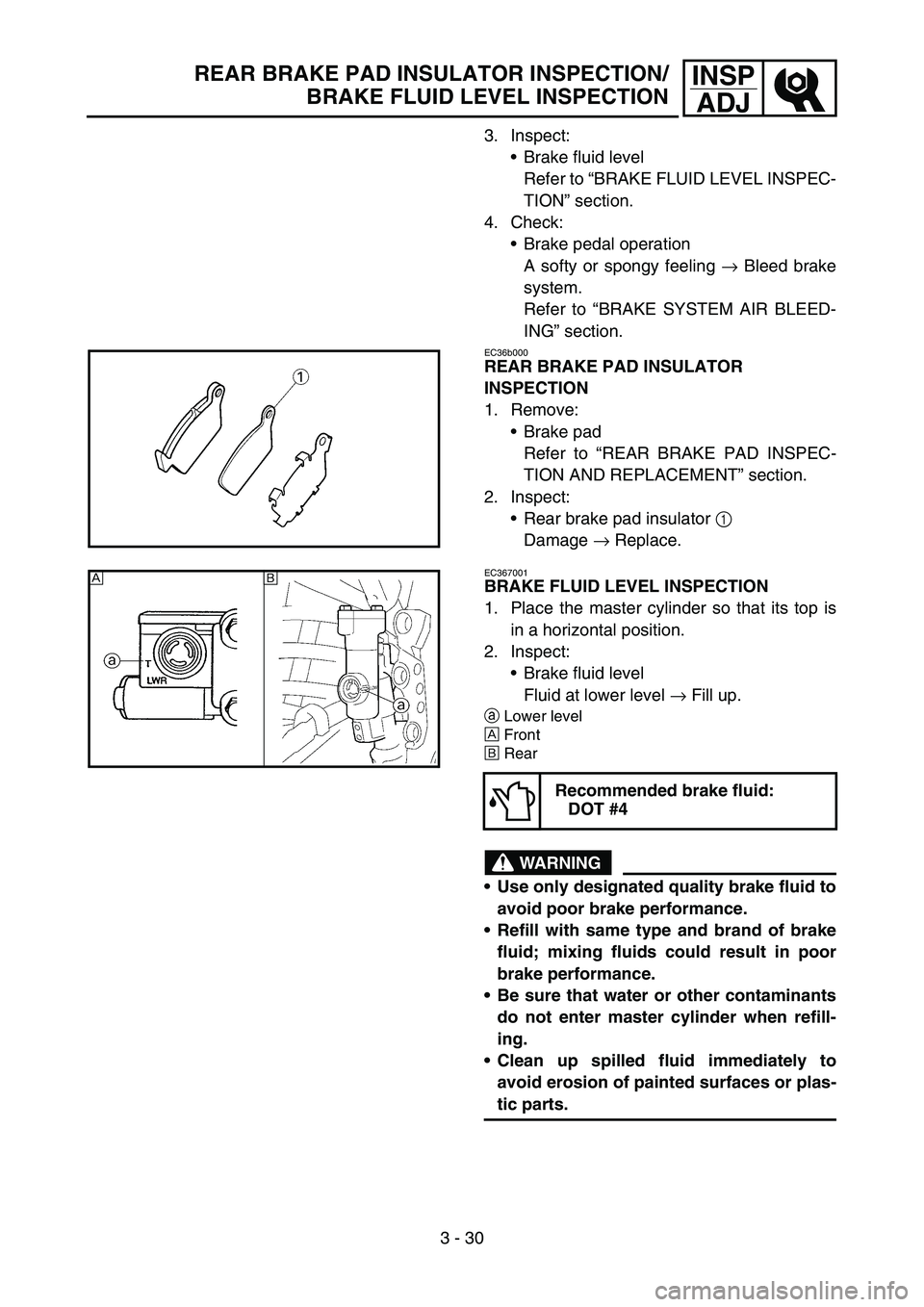
BRAKE FLUID LEVEL INSPECTION
1. Place the master cylinder so that its top is
in a horizontal position.
2. Inspect:
Brake fluid level
Fluid at lower level → Fill up.
aLower level
ÈFront
ÉRear
WARNING
Use only designated quality brake fluid to
avoid poor brake performance.
Refill with same type and brand of brake
fluid; mixing fluids could result in poor
brake performance.
Be sure that water or other contaminants
do not enter master cylinder when refill-
ing.
Clean up spilled fluid immediately to
avoid erosion of painted surfaces or plas-
tic parts.
Recommended brake fluid:
DOT #4
ÈÉ
Page 210 of 650
3 - 32
INSP
ADJ
DRIVE CHAIN SLACK ADJUSTMENT
4. Check:
Drive chain stiffness a
Clean and oil the chain and hold as illus-
trated.
Stiff → Replace drive chain.
5. Install:
Drive chain 1
Joint 2
Master link clip 3
CAUTION:
Be sure to install the master link clip to the
direction as shown.
aTurning direction
New
6. Lubricate:
Drive chain
Drive chain lubricant:
SAE 10W-30 motor oil or
suitable chain lubricants
DRIVE CHAIN SLACK ADJUSTMENT
1. Elevate the rear wheel by placing the suit-
able stand under the engine.
2. Check:
Drive chain slack a
Above the seal guard installation bolt.
Out of specification → Adjust.
NOTE:
Before checking and/or adjusting, rotate the
rear wheel through several revolutions and
check the slack several times to find the tight-
est point. Check and/or adjust chain slack with
rear wheel in this “tight chain” position.
Drive chain slack:
48 ~ 58 mm (1.9 ~ 2.3 in)
Page 228 of 650
3 - 41
INSP
ADJTIRE PRESSURE CHECK/SPOKES INSPECTION AND
TIGHTENING/WHEEL INSPECTION
EC36Q000
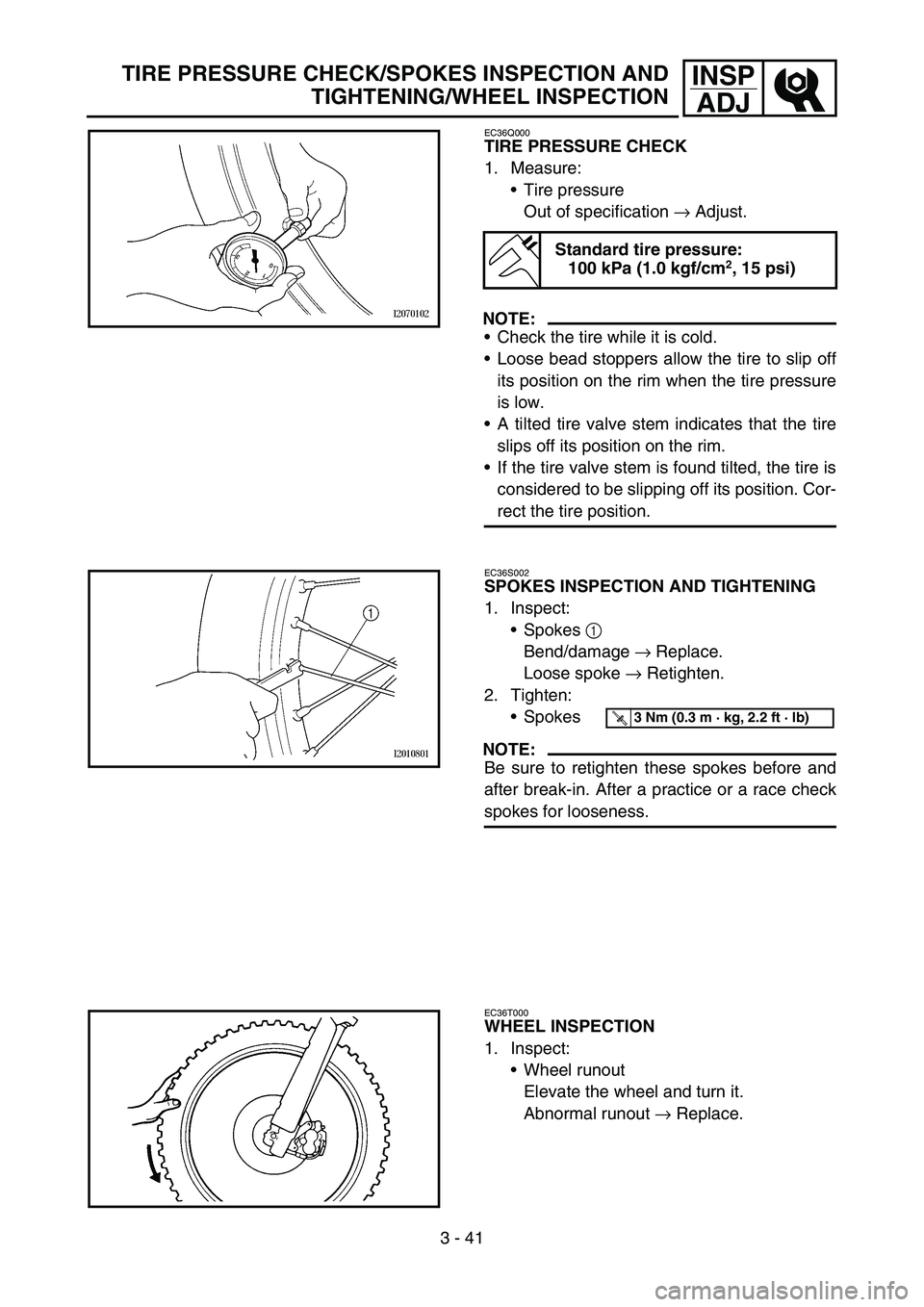
TIRE PRESSURE CHECK
1. Measure:
Tire pressure
Out of specification → Adjust.
NOTE:
Check the tire while it is cold.
Loose bead stoppers allow the tire to slip off
its position on the rim when the tire pressure
is low.
A tilted tire valve stem indicates that the tire
slips off its position on the rim.
If the tire valve stem is found tilted, the tire is
considered to be slipping off its position. Cor-
rect the tire position.
Standard tire pressure:
100 kPa (1.0 kgf/cm2, 15 psi)
EC36S002
SPOKES INSPECTION AND TIGHTENING
1. Inspect:
Spokes 1
Bend/damage → Replace.
Loose spoke → Retighten.
2. Tighten:
Spokes
NOTE:
Be sure to retighten these spokes before and
after break-in. After a practice or a race check
spokes for looseness.
T R..3 Nm (0.3 m · kg, 2.2 ft · lb)
EC36T000
WHEEL INSPECTION
1. Inspect:
Wheel runout
Elevate the wheel and turn it.
Abnormal runout → Replace.
Page 230 of 650
3 - 42
INSP
ADJ
STEERING HEAD INSPECTION AND ADJUSTMENT
2. Inspect:
Bearing free play
Exist play → Replace.
STEERING HEAD INSPECTION AND
ADJUSTMENT
1. Elevate the front wheel by placing a suit-
able stand under the engine.
2. Check:
Steering shaft
Grasp the bottom of the forks and gently
rock the fork assembly back and forth.
Free play → Adjust steering head.
3. Check:
Steering smooth action
Turn the handlebar lock to lock.
Unsmooth action → Adjust steering ring
nut.
4. Adjust:
Steering ring nut
Steering ring nut adjustment steps:
Remove the number plate.
Remove the handlebar and handle crown.
Loosen the ring nut 1 using the ring nut
wrench 2.
Ring nut wrench:
YU-33975/90890-01403
Page 232 of 650
3 - 43
INSP
ADJ
STEERING HEAD INSPECTION AND ADJUSTMENT
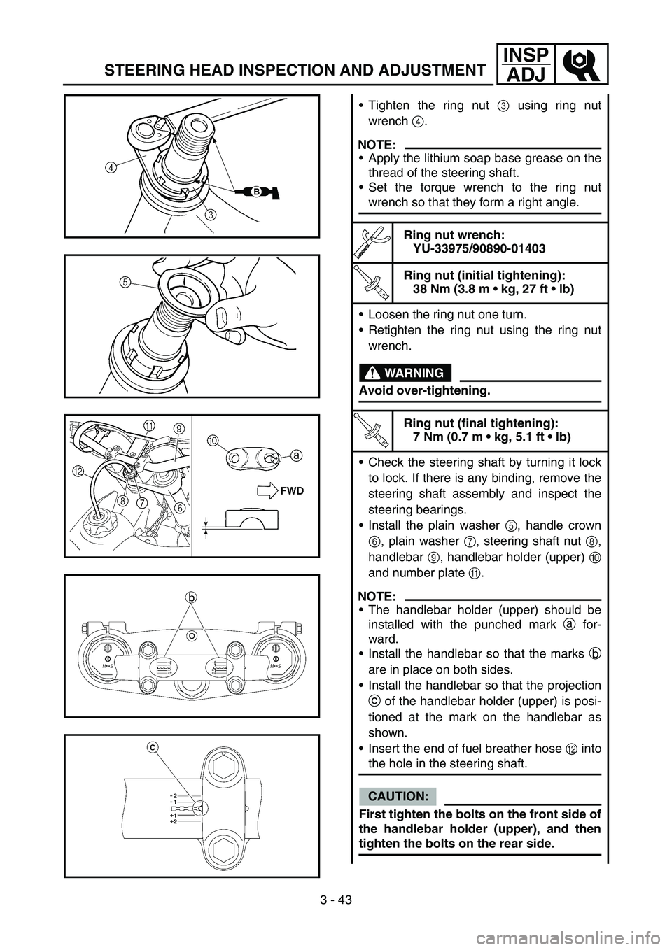
Tighten the ring nut 3 using ring nut
wrench 4.
NOTE:
Apply the lithium soap base grease on the
thread of the steering shaft.
Set the torque wrench to the ring nut
wrench so that they form a right angle.
Ring nut wrench:
YU-33975/90890-01403
T R..
Ring nut (initial tightening):
38 Nm (3.8 m kg, 27 ft lb)
Loosen the ring nut one turn.
Retighten the ring nut using the ring nut
wrench.
WARNING
Avoid over-tightening.
T R..
Ring nut (final tightening):
7 Nm (0.7 m kg, 5.1 ft lb)
Check the steering shaft by turning it lock
to lock. If there is any binding, remove the
steering shaft assembly and inspect the
steering bearings.
Install the plain washer 5, handle crown
6, plain washer 7, steering shaft nut 8,
handlebar 9, handlebar holder (upper) 0
and number plate A.
NOTE:
The handlebar holder (upper) should be
installed with the punched mark a for-
ward.
Install the handlebar so that the marks b
are in place on both sides.
Install the handlebar so that the projection
c of the handlebar holder (upper) is posi-
tioned at the mark on the handlebar as
shown.
Insert the end of fuel breather hose B into
the hole in the steering shaft.
CAUTION:
First tighten the bolts on the front side of
the handlebar holder (upper), and then
tighten the bolts on the rear side.
Page 238 of 650
3 - 46
INSP
ADJ
ELECTRICAL/SPARK PLUG INSPECTION
EC370000
ELECTRICAL
EC371001
SPARK PLUG INSPECTION
1. Remove:
Spark plug
2. Inspect:
Electrode 1
Wear/damage → Replace.
Insulator color 2
Normal condition is a medium to light tan
color.
Distinctly different color → Check the
engine condition.
NOTE:
When the engine runs for many hours at low
speeds, the spark plug insulator will become
sooty, even if the engine and carburetor are in
good operating condition.
3. Measure:
Plug gap a
Use a wire gauge or thickness gauge.
Out of specification → Regap.
Spark plug gap:
0.7 ~ 0.8 mm (0.028 ~ 0.031 in)
4. Clean the plug with a spark plug cleaner if
necessary.
5. Tighten:
Spark plug
NOTE:
Before installing a spark plug, clean the gas-
ket surface and plug surface.
Finger-tighten a the spark plug before torqu-
ing to specification b.
T R..13 Nm (1.3 m · kg, 9.4 ft · lb)
Page 240 of 650
3 - 47
INSP
ADJ
IGNITION TIMING CHECK
IGNITION TIMING CHECK
1. Remove:
Timing plug 1
2. Attach:
Timing light
Inductive tachometer
To the ignition coil lead
(orange lead 1).
Timing light:
YM-33277-A/90890-03141
3. Adjust:
Engine idling speed
Refer to “IDLE SPEED ADJUSTMENT”.
4. Check:
Ignition timing
Visually check the stationary pointer a is
within the firing range b on the rotor.
Incorrect firing range → Check rotor and
pickup assembly.
5. Install:
Timing plug
Page 266 of 650
4 - 13
ENGCARBURETOR
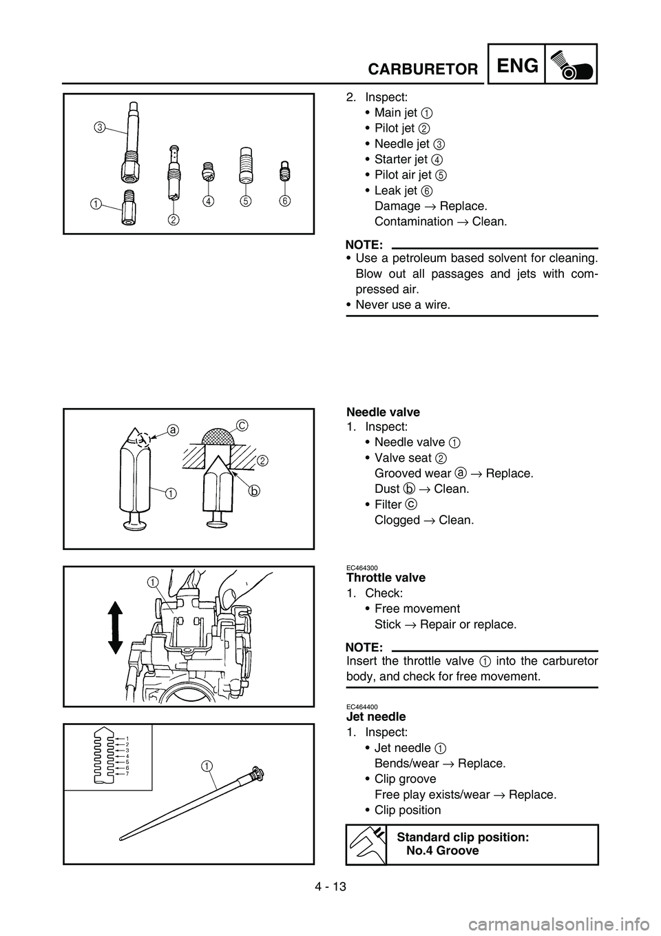
2. Inspect:
Main jet 1
Pilot jet 2
Needle jet 3
Starter jet 4
Pilot air jet 5
Leak jet 6
Damage → Replace.
Contamination → Clean.
NOTE:
Use a petroleum based solvent for cleaning.
Blow out all passages and jets with com-
pressed air.
Never use a wire.
Needle valve
1. Inspect:
Needle valve 1
Valve seat 2
Grooved wear a → Replace.
Dust b → Clean.
Filter c
Clogged → Clean.
EC464300
Throttle valve
1. Check:
Free movement
Stick → Repair or replace.
NOTE:
Insert the throttle valve 1 into the carburetor
body, and check for free movement.
EC464400
Jet needle
1. Inspect:
Jet needle 1
Bends/wear → Replace.
Clip groove
Free play exists/wear → Replace.
Clip position
Standard clip position:
No.4 Groove