Page 409 of 596

5-19
CHAS
FREIN AVANT ET FREIN ARRIERE
VORDERRADBREMSE UND HINTERRADBREMSE
FRENO ANTERIORE E FRENO POSTERIORE
Hauptbremszylindersatz
1. Reinigen:
9Hauptbremszylinder
9Hauptbremszylindereinsatz
Mit Bremsflüssigkeit reinigen.
2. Einbauen:
9Hauptbremszylinderkoppe
(Primär) 1
9Hauptbremszylinderkoppe
(Sekundär) 2
Zum Hauptbremszylinderkol-
ben 3.
HINWEIS:
Bremsflüssigkeit auf die Hauptbrems-
zylinderkoppe auftragen.
W
Nach dem Einbau sollte die Zylin-
dermanschette in der gezeigten
Richtung installiert werden.
Falscher Einbau führt zu Beein-
trächtigung der Bremsleistung.
AVorn
BHinten
Kit de maître-cylindre
1. Nettoyer:
9Maître-cylndre
9Kit de maître-cylindre
Les nettoyer avec le liquide de
frein.
2. Monter:
9Coupelle du maître-cylindre
(primaire) 1
9Coupelle du maître-cylindre
(secondaire) 2
Au piston de maître-cylindre 3.
N.B.:
Appliquer le liquide de frein sur la cou-
pelle du maître-cylindre.
XG
Après la repose, la coupelle du
maître-cylindre doit être posée dans
la direction indiquée. Une mauvaise
intallation entaîne une performance
incorrecte du freinage.
AAvant
BArrière
IC5A5220
Kit del cilindro principale
1. Pulire:
9Cilindro principale
9Kit del cilindro principale
Pulirli con liquido per freni.
2. Installare:
9Anello conico del cilindro prin-
cipale (primario) 1
9Anello conico del cilindro prin-
cipale (secondario) 2
Sul pistone del cilindro princi-
pale 3.
NOTA:
Applicare il liquido per freni sull’anello
conico del cilindro principale.
T
Dopo l’installazione, l’anello conico
del cilindro dovrebbe essere installa-
to nella direzione illustrata.
Un’installazione errata provoca un
rendimento frenante improprio.
AAnteriore
BPosteriore
3. Einbauen:
9Feder 1
Zum Hauptbremszylinderkol-
ben 2.
HINWEIS:
Die Feder mit dem kleineren Durch-
messer einbauen.
AVorn
BHinten
3. Monter:
9Ressort 1
Au piston de maître-cylindre 2.
N.B.:
Reposer le ressort au côté du diamètre
plus petit.
AAvant
BArrière3. Installare:
9Molla 1
Sul pistone del cilindro princi-
pale 2.
NOTA:
Installare la molla sul lato del diametro
più piccolo.
AAnteriore
BPosteriore
1P8-9-32-5a 4/10/06 4:40 PM Page 39
Page 410 of 596
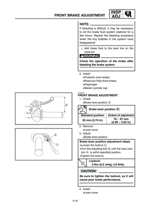
![YAMAHA YZ250LC 2007 Manuale duso (in Italian) 5-20
CHASFRONT BRAKE AND REAR BRAKE
4. Install:
[Front]
9Master cylinder kit 1
9Plain washer 2
9Circlip 3
9Master cylinder boot 4
To master cylinder 5.
[Rear]
9Master cylinder kit 1
9Push rod 2
9Circ YAMAHA YZ250LC 2007 Manuale duso (in Italian) 5-20
CHASFRONT BRAKE AND REAR BRAKE
4. Install:
[Front]
9Master cylinder kit 1
9Plain washer 2
9Circlip 3
9Master cylinder boot 4
To master cylinder 5.
[Rear]
9Master cylinder kit 1
9Push rod 2
9Circ](/manual-img/51/53963/w960_53963-409.png)
5-20
CHASFRONT BRAKE AND REAR BRAKE
4. Install:
[Front]
9Master cylinder kit 1
9Plain washer 2
9Circlip 3
9Master cylinder boot 4
To master cylinder 5.
[Rear]
9Master cylinder kit 1
9Push rod 2
9Circlip 3
9Master cylinder boot 4
To master cylinder 5.
NOTE:
9Apply the brake fluid on the master cylinder
kit.
9Apply the lithium soap base grease on the tip
of the push rod.
9When installing the circlip, use a long nose
circlip pliers.
AFront
BRear
EC5A5310
Front master cylinder
1. Install:
9Master cylinder 1
9Master cylinder bracket 2
9Bolt (master cylinder bracket) 3
NOTE:
9Install the bracket so that the arrow mark a
face upward.
9First tighten the bolts on the upper side of the
master cylinder bracket, and then tighten the
bolts on the lower side.
9 Nm (0.9 m•kg, 6.5 ft•lb)
2. Install:
9Brake lever 1
9Bolt (brake lever) 2
9Nut (brake lever) 3
NOTE:
Apply the lithium soap base grease on the
brake lever sliding surface, bolt and contacting
surface of the master cylinder piston.
6 Nm (0.6 m•kg, 4.3 ft•lb)
1P8-9-32-5a 4/10/06 4:40 PM Page 40
Page 411 of 596
![YAMAHA YZ250LC 2007 Manuale duso (in Italian) 5-20
CHAS
FREIN AVANT ET FREIN ARRIERE
VORDERRADBREMSE UND HINTERRADBREMSE
FRENO ANTERIORE E FRENO POSTERIORE
4. Monter:
[Avant]
9Kit de maître-cylindre 1
9Rondelle ordinaire 2
9Circlip 3
9Soufflet d YAMAHA YZ250LC 2007 Manuale duso (in Italian) 5-20
CHAS
FREIN AVANT ET FREIN ARRIERE
VORDERRADBREMSE UND HINTERRADBREMSE
FRENO ANTERIORE E FRENO POSTERIORE
4. Monter:
[Avant]
9Kit de maître-cylindre 1
9Rondelle ordinaire 2
9Circlip 3
9Soufflet d](/manual-img/51/53963/w960_53963-410.png)
5-20
CHAS
FREIN AVANT ET FREIN ARRIERE
VORDERRADBREMSE UND HINTERRADBREMSE
FRENO ANTERIORE E FRENO POSTERIORE
4. Monter:
[Avant]
9Kit de maître-cylindre 1
9Rondelle ordinaire 2
9Circlip 3
9Soufflet de maître-cylindre 4
Au maître-cylindre 5.
[Arrière]
9Kit de maître-cylindre 1
9Champignon de débrayage 2
9Circlip 3
9Soufflet de maître-cylindre 4
Au maître-cylindre 5.
N.B.:
9Appliquer le liquide de frein sur
l’ensemble du maître-cylindre.
9Appliquer de la graisse au lithium sur
l’extrémité du champignon de
débrayage.
9Pour mettre le circlip en place, utiliser
des pinces de circlip à long nez.
AAvant
BArrière
Maître-cylindre avant
1. Monter:
9Maître-cylindre 1
9Etrier de maître-cylindre 2
9Boulon (étrier de maître-
cylindre) 3
N.B.:
9Reposer le support pour que la flèche
asoit dirigée vers le haut.
9Serrer d’abord les boulons sur le côté
supérieur de l’étrier de maître-
cylindre, puis serrer les boulons sur le
côté inférieur.
4. Einbauen:
[Vorn]
9Hauptbremszylindersatz 1
9Unterlegscheibe 2
9Sprengring 3
9Manschette des Hauptbrems-
zylinders 4
Zum Hauptbremszylinder 5.
[Hinten]
9Hauptbremszylindereinsatz 1
9Schubstange 2
9Sprengring 3
9Manschette des Hauptbrems-
zylinders 4
Zum Hauptbremszylinder 5.
HINWEIS:
9Bremsflüssigkeit auf dem Haupt-
bremszylindersatz auftragen.
9Lithiumseifen-Fett am Ende der
Schubstange auftragen.
9Beim Einbauen des Sprengrings
eine Sprengringzange verwenden.
AVorn
BHinten
Vorderrad-Hauptbremszylinder
1. Einbauen:
9Hauptbremszylinder 1
9Hauptbremszylinderhalterung 2
9Schraube (Hauptbremszylin-
derhalterung) 3
HINWEIS:
9Die Halterung so einbauen, dass die
Pfeilmarkierung anach oben
gerichtet ist.
9Zuerst die Schrauben an der Ober-
seite der Hauptbremszylinderhalte-
rung und danach die Schrauben an
der Unterseite festziehen.
4. Installare:
[Anteriormente]
9Kit del cilindro principale 1
9Rosetta 2
9Anello elastico di arresto 3
9Protezione del cilindro principa-
le 4
Sul cilindro principale 5.
[Posteriormente]
9Kit del cilindro principale 1
9Asta di comando 2
9Anello elastico di arresto 3
9Protezione del cilindro principa-
le 4
Sul cilindro principale 5.
NOTA:
9Applicare il liquido per freni sul kit
del cilindro principale.
9Applicare sulla punta dell’asta di
comando il grasso a base di sapone di
litio.
9Quando si installa l’anello elastico di
arresto, usare pinze ad ago per anelli
elastici di arresto.
AAnteriore
BPosteriore
IC5A5310
Cilindro principale anteriore
1. Installare:
9Cilindro principale 1
9Staffa del cilindro principale 2
9Bullone (staffa del cilindro prin-
cipale) 3
NOTA:
9Installare la staffa in modo che la
freccia asia rivolta verso l’alto.
9Serrare dapprima i bulloni sul lato
superiore della staffa del cilindro prin-
cipale e poi serrare i bulloni sul lato
inferiore.
9 Nm (0,9 m•kg, 6,5 ft•lb)
2. Einbauen:
9Bremshebel 1
9Schraube (Bremshebel) 2
9Mutter (Bremshebel) 3
HINWEIS:
Lithiumseifenfett an der Bremshebel-
gleitfläche, an der Schraube und an
der Kontaktfläche des Hauptbremszy-
linders auftragen.
2. Monter:
9Levier de frein 1
9Boulon (levier de frein) 2
9Ecrou (levier de frein) 3
N.B.:
Appliquer de la graisse à base de savon
au lithium sur la surface de coulisse-
ment du levier de frein, sur le boulon et
sur la surface de contact du maître-
cylindre.
2. Installare:
9Leva di comando del freno 1
9Bullone (leva di comando del
freno) 2
9Dado (leva di comando del
freno) 3
NOTA:
Applicare il grasso a base di sapone di
litio sulla superficie di scorrimento
della leva del freno, il bullone e la
superficie di contatto del pistone del
cilindro principale.
6 Nm (0,6 m•kg, 4,3 ft•lb)6 Nm (0,6 m•kg, 4,3 ft•lb)6 Nm (0,6 m•kg, 4,3 ft•lb)
6 Nm (0,6 m•kg, 4,3 ft•lb)6 Nm (0,6 m•kg, 4,3 ft•lb)
6 Nm (0,6 m•kg, 4,3 ft•lb)
1P8-9-32-5a 4/10/06 4:40 PM Page 41
Page 412 of 596
5-21
CHASFRONT BRAKE AND REAR BRAKE
EC5A5401
Rear master cylinder
1. Install:
9Copper washer 1
9Brake hose 2
9Union bolt 3
w
Always use new copper washers.
cC
Install the brake hose so that its pipe por-
tion
a adirects as shown and lightly touch-
es the projection
b bon the master cylinder.
30 Nm (3.0 m•kg, 22 ft•lb)
2. Install:
9Master cylinder 1
9Bolt (master cylinder) 2
10 Nm (1.0 m•kg, 7.2 ft•lb)
3. Install:
9Spring 1
9Brake pedal 2
9O-ring 3
9Bolt (brake pedal) 4
9Clip 5
NOTE:
Apply the lithium soap base grease on the
bolt, O-ring and brake pedal bracket.
26 Nm (2.6 m•kg, 19 ft•lb)
1P8-9-32-5a 4/10/06 4:40 PM Page 42
Page 413 of 596

3. Einbauen:
9Feder 1
9Bremspedal 2
9O-Ring 3
9Schraube (Bremspedal) 4
9Klemme 5
HINWEIS:
Lithium-Fett auf der Schraube, dem
O-Ring und der Bremspedalhalterung
auftragen.
5-21
CHAS
FREIN AVNAT ET FREIN ARRIERE
VORDERRADBREMSE UND HINTERRADBREMSE
FRENO ANTERIORE E FRENO POSTERIORE
Maître-cylindre arrière
1. Monter:
9Rondelle en cuivre 1
9Tuyau de frein 2
9Boulon d’union 3
XG
Toujours utiliser les rondelles en
cuivre neuves.
fF
Installer la tuyau de frein de manière
que la partie avec le tuyau soit a a
dirigée comme indiqué et touche
légèrement b b
la saillie sur le maître-
cylindre.
2. Monter:
9Maître-cylindre 1
9Boulon (maître-cylindre) 2
Hinterrad-Hauptbremszylinder
1. Einbauen:
9Kupferscheibe 1
9Bremsschlauch 2
9Unionschraube 3
W
Immer neue Kupferscheiben ver-
wenden.
dD
Den Bremsschlauch so einbauen,
dass sein Rohrteil a a
gemäß Abbil-
dung angeordnet ist und den Über-
stand b b
am Hauptbremszylinder
leicht berührt.
2. Einbauen:
9Hauptbremszylinder 1
9Schraube (Hauptbremszylin-
der) 2
IC5A5401
Cilindro principale posteriore
1. Installare:
9Rondella in rame 1
9Tubo flessibile del freno 2
9Bullone di unione 3
T
Usare sempre rondelle in rame
nuove.
iI
Installare il tubo flessibile del freno
in modo che la sua parte di tubo a a
sia rivolta come illustrato e tocchi
leggermente la sporgenza b b
sul cilin-
dro principale.
2. Installare:
9Cilindro principale 1
9Bullone (cilindro principale) 2
10 Nm (1,0 m•kg, 7,2 ft•lb)
30 Nm (3,0 m•kg, 22 ft•lb)30 Nm (3,0 m•kg, 22 ft•lb)30 Nm (3,0 m•kg, 22 ft•lb)
10 Nm (1,0 m•kg, 7,2 ft•lb)10 Nm (1,0 m•kg, 7,2 ft•lb)
26 Nm (2,6 m•kg, 19 ft•lb)
3. Monter:
9Ressort 1
9Pédale de frein 2
9Joint torique 3
9Boulon (pédale de frein) 4
9Agrafe 5
N.B.:
Appliquer de la graisse à base de savon
au lithium sur le boulon, le joint torique
et le support de pédale de frein.
26 Nm (2,6 m•kg, 19 ft•lb)
3. Installare:
9Molla 1
9Pedale di comando del freno 2
9Anello di tenuta 3
9Bullone (pedale di comando del
freno) 4
9Fermaglio a graffa 5
NOTA:
Applicare il grasso a base di sapone di
litio sul bullone, sull’anello di tenuta e
sulla staffa del pedale di comando del
freno.
1P8-9-32-5a 4/10/06 4:40 PM Page 43
Page 414 of 596
5-22
CHASFRONT BRAKE AND REAR BRAKE
2. Install:
9Brake hose holder 1
9Bolt (brake hose holder) 2
3. Install:
9Brake hose holder 1
9Nut (brake hose holder) 2
NOTE:
Align the top aof the brake hose holder with the
paint bof the brake hose.
10 Nm (1.0 m•kg, 7.2 ft•lb)
7 Nm (0.7 m•kg, 5.1 ft•lb)
4. Install:
9Pin 1
9Plain washer 2
9Cotter pin 3
NOTE:
After installing, check the brake pedal height.
Refer to “REAR BRAKE ADJUSTMENT” section
in the CHAPTER 3.
EC5A5911
Front brake hose
1. Install:
9Copper washer 1
9Brake hose 2
9Union bolt 3
w
Always use new copper washers.
cC
Install the brake hose so that its pipe por-
tion a a
directs as shown and lightly touch-
es the projection b b
on the caliper.
30 Nm (3.0 m•kg, 22 ft•lb)
1P8-9-32-5a 4/10/06 4:40 PM Page 44
Page 415 of 596

5-22
CHAS
FREIN AVANT ET FREIN ARRIERE
VORDERRADBREMSE UND HINTERRADBREMSE
FRENO ANTERIORE E FRENO POSTERIORE
4. Monter:
9Goupille 1
9Rondelle ordinaire 2
9Goupille fendue 3
N.B.:
Après de montage, contrôler la hauteur
de pédale de frein.
Se reporter à la section “REGLAGE
DU FREIN ARRIERE” du CHAPITRE
3.
Tuyau de frein avant
1. Monter:
9Rondelle en cuivre 1
9Tuyau de frein 2
9Boulon d’union 3
XG
Toujours utiliser les rondelles en
cuivre neuves.
fF
Installer le tuyau de frein de manière
à ce que la partie avec le tuyau a a
soit dirigée comme indiqué et touche
légèrement la saillie b b
sur l’étrier.
2. Monter:
9Support de tuyau de frein 1
9Boulon (support de tuyau de
frein) 2
3. Monter:
9Support de tuyau de frein 1
9Ecrou (support de tuyau de
frein) 2
N.B.:
Aligner le dessus adu support de
tuyau de frein sur la peinture bdu
tuyau de frein.
4. Einbauen:
9Stift 1
9Unterlegscheibe 2
9Splint 3
HINWEIS:
Nach den Einbau, die Höhe des
Bremspedals kontrollieren.
Siehe Abschnitt „EINSTELLUNG DER
HINTERRADBREMSE“ im KAPITEL
3.
Vorderbremsschlauch
1. Einbauen:
9Kupferscheibe 1
9Bremsschlauch 2
9Unionschraube 3
W
Immer neue Kupferscheiben ver-
wenden.
dD
Bremsleitung so einbauen, dass
der Rohrabschnitt a a
wie in der
Abbildung gezeigt angeordnet ist
und den Überstand b b
am Bremsbe-
lag leicht berührt.
2. Einbauen:
9Bremsschlauchhalter 1
9Schraube (Bremsschlauchhal-
ter) 2
3. Einbauen:
9Bremsschlauchhalter 1
9Mutter (Bremsschlauchhalter)
2
HINWEIS:
Die Oberseite ader Bremsschlauch-
Halterung am Anstrich bdes Brems-
schlauches ausrichten.
4. Installare:
9Spina 1
9Rosetta 2
9Coppiglia 3
NOTA:
Dopo l’installazione, controllare l’altez-
za del pedale di comando del freno.
Consultare la sezione “REGOLAZIO-
NE DEL FRENO POSTERIORE” al
CAPITOLO 3.
IC5A5911
Tubo flessibile del freno anteriore
1. Installare:
9Rondella in rame 1
9Tubo flessibile del freno 2
9Bullone di unione 3
T
Usare sempre rondelle in rame
nuove.
iI
Quando si installa il tubo flessibile
del freno sulla pinza, toccare legger-
mente il tubo del freno a a
con la
sporgenza b b
sulla pinza.
2. Installare:
9Supporto del tubo flessibile del
freno 1
9Bullone (supporto del tubo fles-
sibile del freno) 2
3. Installare:
9Supporto del tubo flessibile del
freno 1
9Dado (supporto del tubo flessi-
bile del freno) 2
NOTA:
Allineare la sommità adel supporto
del tubo flessibile del freno con i segni
dipinti bdel tubo flessibile del freno.
10 Nm (1,0 m•kg, 7,2 ft•lb)10 Nm (1,0 m•kg, 7,2 ft•lb)
10 Nm (1,0 m•kg, 7,2 ft•lb)
7 Nm (0,7 m•kg, 5,1 ft•lb)7 Nm (0,7 m•kg, 5,1 ft•lb)
7 Nm (0,7 m•kg, 5,1 ft•lb)
30 Nm (3,0 m•kg, 22 ft•lb)30 Nm (3,0 m•kg, 22 ft•lb)30 Nm (3,0 m•kg, 22 ft•lb)
1P8-9-32-5a 4/10/06 4:40 PM Page 45
Page 416 of 596
5-23
CHASFRONT BRAKE AND REAR BRAKE
4. Pass the brake hose through the cable
guide 1.
5. Install:
9Copper washer 1
9Brake hose 2
9Union bolt 3
w
Always use new copper washers.
cC
Install the brake hose so that its pipe por-
tion a a
directs as shown and lightly touch-
es the projection b b
on the master cylinder.
30 Nm (3.0 m•kg, 22 ft•lb)
EC5A5502
Rear brake hose
1. Install:
9Copper washer 1
9Brake hose 2
9Union bolt 3
w
Always use new copper washers.
cC
Install the brake hose so that its pipe por-
tion a a
directs as shown and lightly touch-
es the projection b b
on the caliper.
30 Nm (3.0 m•kg, 22 ft•lb)
1P8-9-32-5a 4/10/06 4:40 PM Page 46