Page 77 of 140

8-1
1
2
3
4
5
6
78
9
10
11
EBU21654
PERIODIC MAINTENANCE AND MINOR REPAIR
EBU21670
Safety is an obligation of the owner. Periodic in-
spection, adjustment and lubrication will keep your
ATV in the safest and best operating condition
possible. The most important points of inspection,
adjustment, and lubrication are explained on the
following pages.
The intervals given in the periodic maintenance
and lubrication chart should be considered as a
general guide under normal riding conditions.
However, DEPENDING ON THE WEATHER,
TERRAIN, GEOGRAPHICAL LOCATION, AND
INDIVIDUAL USE, THE MAINTENANCE INTER-
VALS MAY NEED TO BE SHORTENED.
WARNING
EWB01840
Never service an engine while it is running.
Moving parts can catch clothing or parts of the
body, causing injury. Electrical components
can cause shocks or start fires. Turn off the en-
gine when performing maintenance unless
otherwise specified. Have a Yamaha dealer
perform the service if you are not familiar with
maintenance work.
EBU21690
Owner’s manual and tool kit
Be sure to put this owner’s manual and the low-
pressure tire gauge in the plastic bag and always
carry them along with the owner’s tool kit under the
seat.
1. Owner’s manual
2. Low-pressure tire gauge
3. Owner’s tool kit
1
23
Page 78 of 140
8-2
1
2
3
4
5
6
78
9
10
11
The service information included in this manual
and the tools provided in the owner’s tool kit are in-
tended to assist you in the performance of preven-
tive maintenance and minor repairs. However,
additional tools such as a torque wrench may be
necessary to perform certain maintenance work
correctly.
NOTE:
If you do not have the tools or experience required
for a particular job, have a Yamaha dealer perform
it for you.
WARNING
EWB01850
Never modify this ATV through improper in-
stallation or use of accessories, as it may
cause changes in handling, which in some sit-
uations could lead to an accident. All parts and
accessories added to this ATV should be gen-
uine Yamaha or equivalent components de-
signed for use on this ATV and should be
installed and used according to instructions. If
you have questions, consult an authorized
Yamaha ATV dealer.
Page 88 of 140

8-12
1
2
3
4
5
6
78
9
10
11
5. Remove the reservoir cap, add coolant or dis-
tilled water to the maximum level mark, and
then install the reservoir cap.
CAUTION:
ECB00401
�
If coolant is not available, use distilled water
or soft tap water instead. Do not use hard wa-ter or salt water since it is harmful to the en-
gine.
�
If water has been used instead of coolant, re-
place it with coolant as soon as possible,
otherwise the cooling system will not be pro-
tected against frost and corrosion.
�
If water has been added to the coolant, have
a Yamaha dealer check the antifreeze con-
tent of the coolant as soon as possible, oth-
erwise the effectiveness of the coolant will
be reduced.
6. Close the coolant reservoir cover.
7. Install the seat.
NOTE:
If the engine overheats, see page 8-51 for further
instructions.
EBU23521
To change the coolant
WARNING
EWB01890
Wait for the engine and radiator to cool before
removing the radiator cap. You could be
burned by hot fluid and steam blown out under
pressure. Always place a thick rag over the cap
1. Coolant reservoir cover
2. Coolant reservoir cap
Coolant reservoir capacity (up to the maximum
level mark):
0.28 L (0.30 US qt) (0.25 Imp.qt)
1
2
Page 94 of 140
8-18
1
2
3
4
5
6
78
9
10
11
5. Wash the sponge material gently but thor-
oughly in solvent.
WARNING
EWB01940
Always use parts cleaning solvent to clean the
sponge material. Never use low-flash-point
solvents or gasoline to clean the sponge mate-
rial because the engine could catch fire or ex-
plode.
6. Squeeze the excess solvent out of the sponge
material and let it dry.CAUTION:
ECB00440
Do not twist the sponge material when squeez-
ing it.
7. Check the sponge material and replace it if
damaged.
8. Apply a quality foam air filter oil to the sponge
material.
NOTE:
The sponge material should be wet but not drip-
ping.
9. Pull the sponge material over the air filter ele-
ment frame, and then install the lock plate by
turning it.
1. Sponge material
2. Air filter element frame
3. Air filter element lock plate
1 22
1
3
Page 96 of 140
8-20
1
2
3
4
5
6
78
9
10
11
2. Remove the tailpipe by pulling it out of the
muffler.
3. Tap the tailpipe lightly, and then use a wire
brush to remove any carbon deposits from the
spark arrester portion of the tailpipe and inside
of the tailpipe housing.4. Make sure the gasket is properly positioned,
then insert the tailpipe into the muffler and
align the screw holes.
5. Install the screws and tighten them.
WARNING
EWB02340
Do not start the engine when cleaning the
spark arrester, otherwise it could cause injury
to the eyes, burns, carbon monoxide poison-
ing, possibly leading to death, and start a fire.
Always let the exhaust system cool prior to
1. Screw
1
1. Tailpipe
2. Spark arrester
3. Gasket
1
2
3
Page 97 of 140

8-21
1
2
3
4
5
6
78
9
10
11
touching exhaust components.
EBU23992
Changing the carburetor settings
In extremely cold weather, it is necessary to
change the carburetor settings to maintain opti-
mum engine performance and to prevent engine
damage.
WARNING
EWB01990
�
Improperly servicing or adjusting the carbu-
retors could cause them to malfunction with
the possibility of an accident, or the carbure-
tors could leak fuel, which would be a fire
hazard.
�
Carburetor adjustments should only be per-
formed by a Yamaha dealer. Do not attempt
to perform these procedures unless you
have mechanical knowledge and the neces-
sary tools.
�
Do not perform this procedure while the en-
gine is hot. Place a rag under each carbure-
tor to catch any fuel. Wipe up any spilled fuel
completely.
�
After servicing the carburetors, always
check the throttle lever operation before op-erating the ATV to make sure it is working
correctly.
Standard settings
Main jet #200
Jet needle clip position 3rd groove
Pilot air screw 2.0 turns out
1. Main jet number
1
Page 110 of 140
 as shown. If the free
play is incor")
8-34
1
2
3
4
5
6
78
9
10
11
intervals specified in the periodic maintenance and
lubrication chart. The brake lever should have a
free play of zero mm (zero in) as shown. If the free
play is incorrect, have a Yamaha dealer check the
brake system.
WARNING
EWB02070
Operating with improperly serviced or adjust-
ed brakes could cause loss of braking ability,
which could lead to an accident.
After servicing:
�
Make sure the brakes operate smoothly and
that the free play is correct.
�
Make sure the brakes do not drag.
�
Make sure the brakes are not spongy. All air
must be bled from the brake system.
Replacement of brake components requires
professional knowledge. These procedures
should be performed by a Yamaha dealer.
EBU24611
Checking the brake pedal position
The brake pedal position must be checked and, if
necessary, adjusted at the intervals specified in
the periodic maintenance and lubrication chart.
The top of the brake pedal should be positioned
10.0 mm (0.39 in) below the top of the footrest as
shown. If the brake pedal is not positioned as spec-
ified, have a Yamaha dealer adjust it.
1. Brake lever free play
1
Page 111 of 140
8-35
1
2
3
4
5
6
78
9
10
11
WARNING
EWB02110
Operating with improperly serviced or adjust-
ed brakes could cause loss of braking ability,
which could lead to an accident.
After servicing:
�
Make sure the brakes operate smoothly and
that the brake pedal position is correct.
�
Make sure the brakes do not drag.
�
Make sure the brakes are not spongy. All air
must be bled from the brake system.
Replacement of brake components requires
professional knowledge. These procedures
should be performed by a Yamaha dealer.
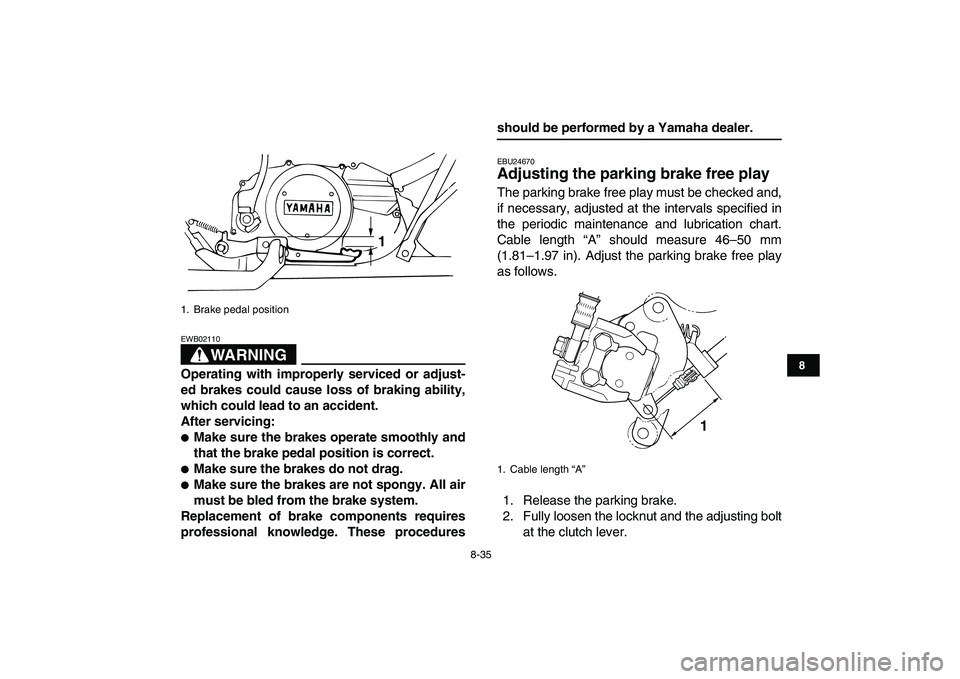
EBU24670
Adjusting the parking brake free play
The parking brake free play must be checked and,
if necessary, adjusted at the intervals specified in
the periodic maintenance and lubrication chart.
Cable length “A” should measure 46–50 mm
(1.81–1.97 in). Adjust the parking brake free play
as follows.
1. Release the parking brake.
2. Fully loosen the locknut and the adjusting bolt
at the clutch lever.
1. Brake pedal position
1
1. Cable length “A”
1