2007 SUZUKI SWIFT Oul
[x] Cancel search: OulPage 376 of 1496
Downloaded from www.Manualslib.com manuals search engine 1G-1 Fuel System:
Engine
Fuel System
Precautions
Precautions on Fuel System ServiceS7RS0B1700001
WARNING!
Before attempting service of any type on fuel system, the following should be always observed in
order to reduce the risk of fire and personal injury.
• Disconnect negative cable at battery.
• Do not smoke, and place no smoking signs near work area.
• Be sure to have CO
2 fire extinguisher handy.
• Be sure to perform work in a well-ventilated area and away from any open flames (such as gas hot heater).
• Wear safety glasses.
• To relieve fuel vapor pressure in fuel tank, remove fuel filler cap from fuel filler neck and then
reinstall it.
• As fuel feed line is still under high fuel pr essure even after stopping engine, loosening or
disconnecting fuel feed line directly may cause dangerous spout of fuel. Before loosening or
disconnecting fuel feed line, make sure to relieve fuel pressure referring to “Fuel Pressure Relief
Procedure”.
• A small amount of fuel may be released when the fuel line is disconnected. In order to reduce the risk of personal injury, cover a shop cloth to the fitting to be disconnected. Be sure to put that cloth
in an approved container after disconnecting.
• Never run engine with fuel pump relay disconnected when engine and exhaust system are hot.
• Note that fuel hose connection varies with each type of pipe. Be sure to connect and clamp each hose correctly referring to “Fuel Hose Disconnecting and Reconnecting”.
After connecting, make sure that it has no twist or kink.
• When installing inje ctor or fuel feed pipe, lubr icate its O-ring with gasoline.
General Description
Fuel System DescriptionS7RS0B1701001
CAUTION!
This engine requires the unleaded fuel only.
The leaded and/or low lead fuel can result in
engine damage and reduce the effectiveness
of the emission control system.
The main components of the fuel system are fuel tank,
fuel pump assembly (with fuel filter, fuel level gauge, fuel
pressure regulator, fuel feed line and fuel vapor line.
For the details of fuel flow, refer to “Fuel Delivery System
Diagram”.
Fuel Delivery System DescriptionS7RS0B1701002
The fuel delivery system consists of the fuel tank, fuel
pump assembly (with built-in f uel filter and fuel pressure
regulator), delivery pipe, injectors and fuel feed line.
The fuel in the fuel tank is pumped up by the fuel pump,
sent into delivery pipe and injected by the injectors.
As the fuel pump assembly is equipped with built-in fuel
filter and fuel pressure regulator, the fuel is filtered and
its pressure is regulated before being sent to the feed
pipe.
The excess fuel at fuel pressure regulation process is
returned back into the fuel tank.
Also, fuel vapor generated in fuel tank is led through the
fuel vapor line into the EVAP canister.
For system diagram, refer to “Fuel Delivery System
Diagram”.
Page 383 of 1496
Downloaded from www.Manualslib.com manuals search engine Fuel System: 1G-8
Installation1) Install clamps to marked location on pipes. If clamp is deformed, its claw is bent or broken, replace it with
new one.
2) Install pipes with pipe clamps to vehicle.
3) Connect fuel hoses and pipes to each pipe referring to “Fuel Hose Disconnecting and Reconnecting”.
4) Connect negative cable at battery.
5) With engine OFF, turn igniti on switch to ON position
and check for fuel leaks.
Fuel Injector On-Vehicle InspectionS7RS0B1706007
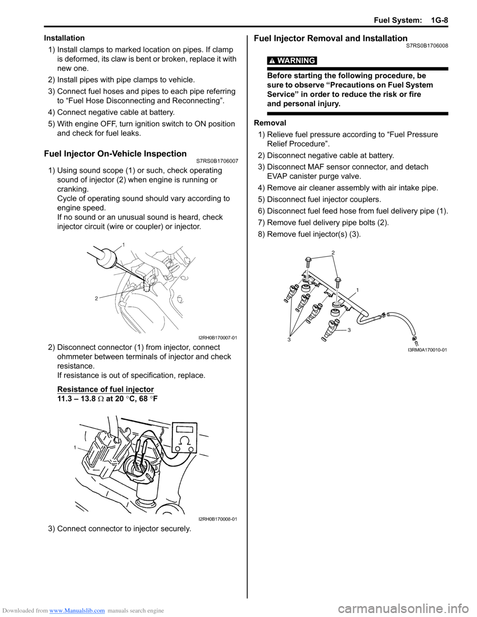
1) Using sound scope (1) or such, check operating sound of injector (2) when engine is running or
cranking.
Cycle of operating sound should vary according to
engine speed.
If no sound or an unusual sound is heard, check
injector circuit (wire or coupler) or injector.
2) Disconnect connector (1) from injector, connect ohmmeter between terminals of injector and check
resistance.
If resistance is out of specification, replace.
Resistance of fuel injector
11.3 – 13.8 Ω at 20 °C, 68 °F
3) Connect connector to injector securely.
Fuel Injector Removal and InstallationS7RS0B1706008
WARNING!
Before starting the following procedure, be
sure to observe “Precautions on Fuel System
Service” in order to reduce the risk or fire
and personal injury.
Removal 1) Relieve fuel pressure according to “Fuel Pressure Relief Procedure”.
2) Disconnect negative cable at battery.
3) Disconnect MAF sensor connector, and detach EVAP canister purge valve.
4) Remove air cleaner assembly with air intake pipe.
5) Disconnect fuel injector couplers.
6) Disconnect fuel feed hose from fuel delivery pipe (1).
7) Remove fuel delivery pipe bolts (2).
8) Remove fuel injector(s) (3).
I2RH0B170007-01
I2RH0B170008-01
2
1
3
3
I3RM0A170010-01
Page 385 of 1496

Downloaded from www.Manualslib.com manuals search engine Fuel System: 1G-10
4) Install suitable vinyl tube onto injector nozzle to
prevent fuel from splashing out when injecting.
5) Put graduated cylinder under injector.
6) Operate fuel pump and apply fuel pressure to
injector as follows:
a) When using scan tool:
i) Connect scan tool to DLC with ignition switch OFF.
ii) Turn ignition switch ON, clear DTC and select “MISC TEST” mode on scan tool.
iii) Turn fuel pump ON by using scan tool.
Special tool
(A): SUZUKI scan tool
b) When not using scan tool: i) Remove fuel pump relay from connector.
ii) Connect two terminals of relay connector using service wire (1) as shown in figure.
CAUTION!
Check to make sure that connection is made
between correct terminals. Wrong
connection can cause damage to ECM, wire
harness, etc.
iii) Turn ignition switch ON. 7) Apply battery voltage to in
jector (1) for 15 seconds
and measure injected fuel volume with graduated
cylinder. Test each injector two or three times. If not
within specification, replace injector.
Injected fuel volume
43 – 47 cc/15 sec. (1.45/1.51 – 1.58/1.65 US/lmp
oz/15 sec.)
8) Check fuel leakage from injector nozzle. Do not operate injector for this check (but fuel pump should
be at work). If fuel leaks (1) more than the following
specifications, replace.
Fuel leakage
Less than 1 drop/min.
Fuel Filler Cap InspectionS7RS0B1706010
WARNING!
Before starting the following procedure, be
sure to observe “Precautions on Fuel System
Service” in order to reduce the risk or fire
and personal injury.
Remove cap (1), and che ck gasket for even filler neck
imprint, and deterioration or any damage. If gasket (2) is
in malcondition, replace cap.
NOTE
If cap requires replacement, only a cap with
the same features should be used. Failure to
use correct cap can result in fire and
personal injury.
(A)I4RS0A170021-01
1
I4RS0A170006-02
I2RH0B170013-01
I2RH01170008-01
Page 389 of 1496

Downloaded from www.Manualslib.com manuals search engine Fuel System: 1G-14
Fuel Tank Purging ProcedureS7RS0B1706015
WARNING!
• Before starting the following procedure, be sure to observe “Precautions on Fuel
System Service” in order to reduce the risk
or fire and personal injury.
• This purging procedure will not remove all fuel vapor.
Do not attempt any repair on tank using
heat of flame as an explosion resulting in
personal injury could occur.
CAUTION!
Never remain water in fu el tank after washing,
or fuel tank inside will get corrosion.
The following procedure are used for purging fuel tank.
1) After removing fuel tank, remove all hoses, pipes and fuel pump assembly from fuel tank.
2) Drain all remaining fuel from tank.
3) Place fuel tank to flushing area.
4) Fill tank with warm water or tap water, and agitate
vigorously and drain. Repeat this washing until
inside of tank is clean. Replace tank if its inside is
rusty.
5) Completely flush out rema ining water after washing.
Fuel Pump On-Vehicle InspectionS7RS0B1706016
WARNING!
Before starting the following procedure, be
sure to observe “Precautions on Fuel System
Service” in order to reduce the risk or fire
and personal injury.
NOTE
The fuel pressure regulator is incorporated
with the fuel pump assembly so individual
inspection of it is impossible.
1) Remove filler cap and turn ON ignition switch (2).
Then fuel pump operating sound should be heard
from fuel filler (1) for about 2 seconds and stop. Be
sure to reinstall fuel filler cap after checking.
If the check result is not satisfactory, go to “Fuel
Pump and Its Circuit Check in Section 1A”. 2) Turn OFF ignition switch and leave over 10 minutes
as it is.
3) Fuel pressure should be felt at fuel feed hose (1) for about 2 seconds after ignition switch ON.
If fuel pressure is not felt, go to “Fuel Pressure
Check in Section 1A”.
Fuel Pump Assembly Removal and InstallationS7RS0B1706017
WARNING!
Before starting the following procedure, be
sure to observe “Precautions on Fuel System
Service” in order to reduce the risk or fire
and personal injury.
Removal
1) Remove fuel tank from vehicle. Refer to “Fuel Tank Removal and Installation”.
2) Disconnect fuel feed pipe (1) from fuel pump assembly (2) referring to “Fuel Hose Disconnecting
and Reconnecting”.
IVSY01170013-01
1I3RM0A170019-01
1
2
I6RS0C170008-02
Page 402 of 1496
Downloaded from www.Manualslib.com manuals search engine 1I-1 Starting System:
Engine
Starting System
Schematic and Routing Diagram
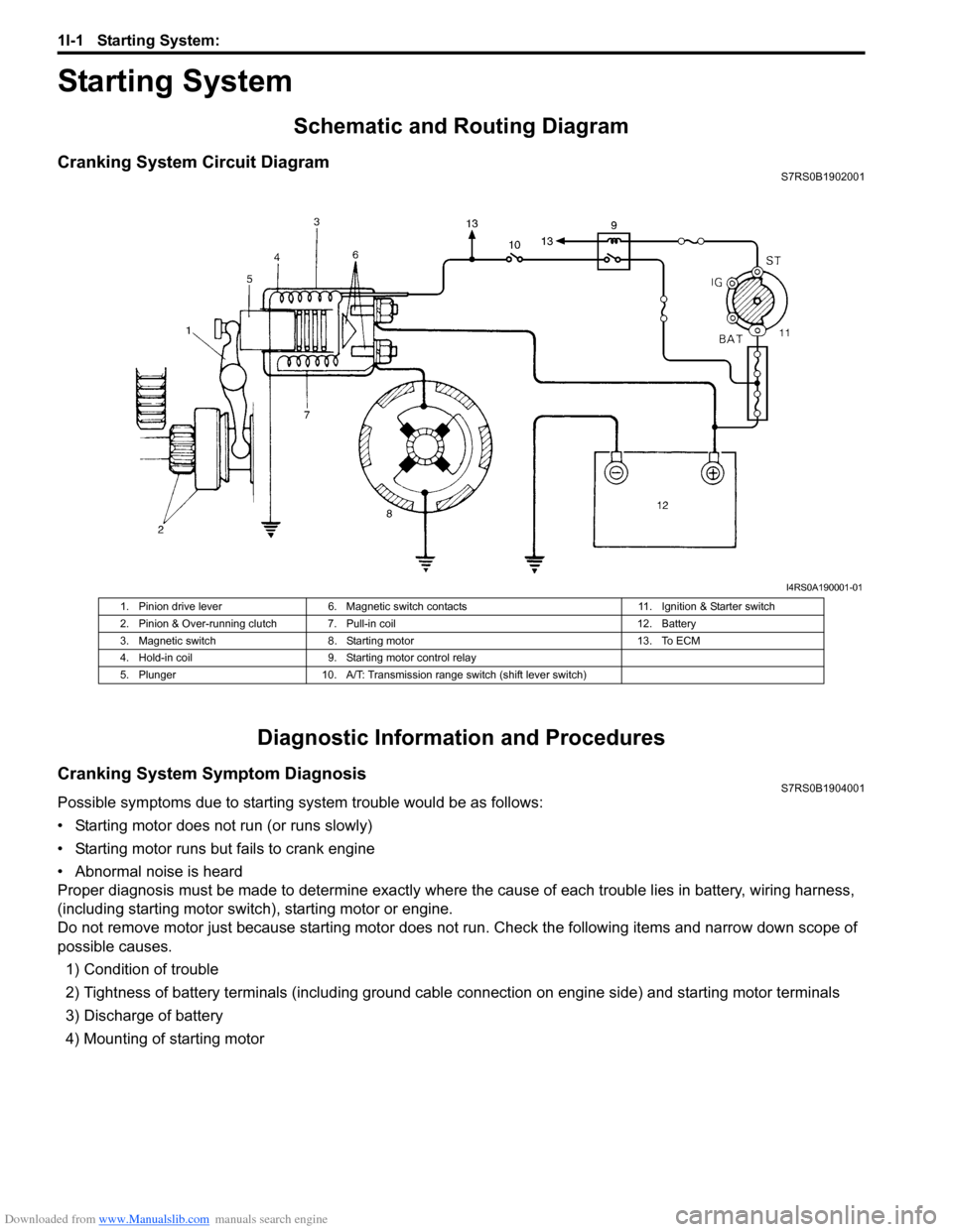
Cranking System Circuit DiagramS7RS0B1902001
Diagnostic Information and Procedures
Cranking System Symptom DiagnosisS7RS0B1904001
Possible symptoms due to starting system trouble would be as follows:
• Starting motor does not run (or runs slowly)
• Starting motor runs but fails to crank engine
• Abnormal noise is heard
Proper diagnosis must be made to determine exactly where the cause of each trouble lies in battery, wiring harness,
(including starting motor switch), starting motor or engine.
Do not remove motor just because starting motor does not run. Check the following items and narrow down scope of
possible causes.
1) Condition of trouble
2) Tightness of battery terminals (including ground cable connection on engine side) and starting motor terminals
3) Discharge of battery
4) Mounting of starting motor
I4RS0A190001-01
1. Pinion drive lever 6. Magnetic switch contacts 11. Ignition & Starter switch
2. Pinion & Over-running clutch 7. Pull-in coil 12. Battery
3. Magnetic switch 8. Starting motor 13. To ECM
4. Hold-in coil 9. Starting motor control relay
5. Plunger 10. A/T: Transmission range switch (shift lever switch)
Page 407 of 1496

Downloaded from www.Manualslib.com manuals search engine Starting System: 1I-6
Starting Motor InspectionS7RS0B1906003
Plunger
Inspect plunger for wear. Replace if necessary.
Magnetic Switch
Push in plunger and release it. The plunger should
return quickly to its original position. Replace if
necessary.
Pull-in coil open circuit test
Check for continuity across magnetic switch “S” terminal
(1) and “M” terminal (2). If no continuity, coil is open and
should be replaced. Hold-in coil open circuit test
Check for continuity across ma
gnetic switch “S” terminal
(1) and coil case. If no continuity, coil is open and should
be replaced.
Rear Bracket Bush
Inspect bush for wear or damage. Replace if necessary.
Brush
• Check brushes for wear. Measure length of brushes and if below the limit,
replace the brush.
Brush length
Standard: 12.3 mm (0.48 in.)
Limit: 7.0 mm (0.28 in.)
• Install brushes to each brush holder and check for smooth movement.
I2RH01190008-01
I2RH01190009-01
I2RH01190010-01
I2RH01190011-01
I2RH01190012-01
I2RH01190013-01
Page 408 of 1496
Downloaded from www.Manualslib.com manuals search engine 1I-7 Starting System:
Spring
Inspect brush springs for wear, damage or other
abnormal conditions. Replace if necessary.
Brush spring tension
Standard: 2.2 kg (4.85 lb)
Limit: 0.6 kg (1.33 lb)
Brush Holder
• Check movement of brush in brush holder. If brush movement within brush holder is sluggish, check
brush holder for distortion and sliding faces for
contamination.
Clean or correct as necessary.
• Check for continuity across insulated brush (positive side) and grounded brush (negative side).
If continuity exists, brus h holder is grounded due to
defective insulation and should be replaced.
Armature
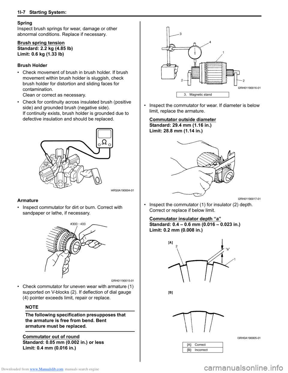
• Inspect commutator for dirt or burn. Correct with sandpaper or lathe, if necessary.
• Check commutator for uneven wear with armature (1) supported on V-blocks (2). If deflection of dial gauge
(4) pointer exceeds limit, repair or replace.
NOTE
The following specification presupposes that
the armature is free from bend. Bent
armature must be replaced.
Commutator out of round
Standard: 0.05 mm (0.002 in.) or less
Limit: 0.4 mm (0.016 in.) • Inspect the commutator for wear. If diameter is below
limit, replace the armature.
Commutator outside diameter
Standard: 29.4 mm (1.16 in.)
Limit: 28.8 mm (1.14 in.)
• Inspect the commutator (1) for insulator (2) depth. Correct or replace if below limit.
Commutator insulator depth “a”
Standard: 0.4 – 0.6 mm (0.016 – 0.023 in.)
Limit: 0.2 mm (0.008 in.)
I4RS0A190004-01
I2RH01190015-01
3. Magnetic stand
[A]: Correct
[B]: Incorrect
I2RH01190016-01
I2RH01190017-01
I3RH0A190005-01
Page 411 of 1496
Downloaded from www.Manualslib.com manuals search engine Charging System: 1J-1
Engine
Charging System
General Description
Battery DescriptionS7RS0B1A01001
The battery has three major functions in the electrical
system.
• It is a source of electrical energy for cranking the engine.
• It acts as a voltage stabilizer for the electrical system.
• It can, for a limited time, provide energy when the electrical load exceeds the output of the generator.
Carrier and Hold-Down
The battery carrier should be in good condition so that it
will support the battery securely and keep it level. Before
installing the battery, the ba ttery carrier and hold-down
clamp should be clean and free from corrosion and
make certain there are no parts in carrier.
To prevent the battery from shaking in its carrier, the
hold-down bolts should be tight enough but not over-
tightened.
Electrolyte Freezing
The freezing point of electrolyte depends on its specific
gravity. Since freezing may ruin a battery, it should be
protected against freezing by keeping it in a fully
charged condition. If a battery is frozen accidentally, it
should not be charged until it is warmed.
Sulfation
If the battery is allowed to stand for a long period in
discharged condition, the lead sulfate becomes
converted into a hard, cryst alline substance, which will
not easily turn back to the active material again during
the subsequent recharging. “Sulfation” means the result
as well as the process of that reaction. Such a battery
can be revived by very slow charging and may be
restored to usable condition but its capacity is lower than
before. Built-In Indicator (If Equipped)
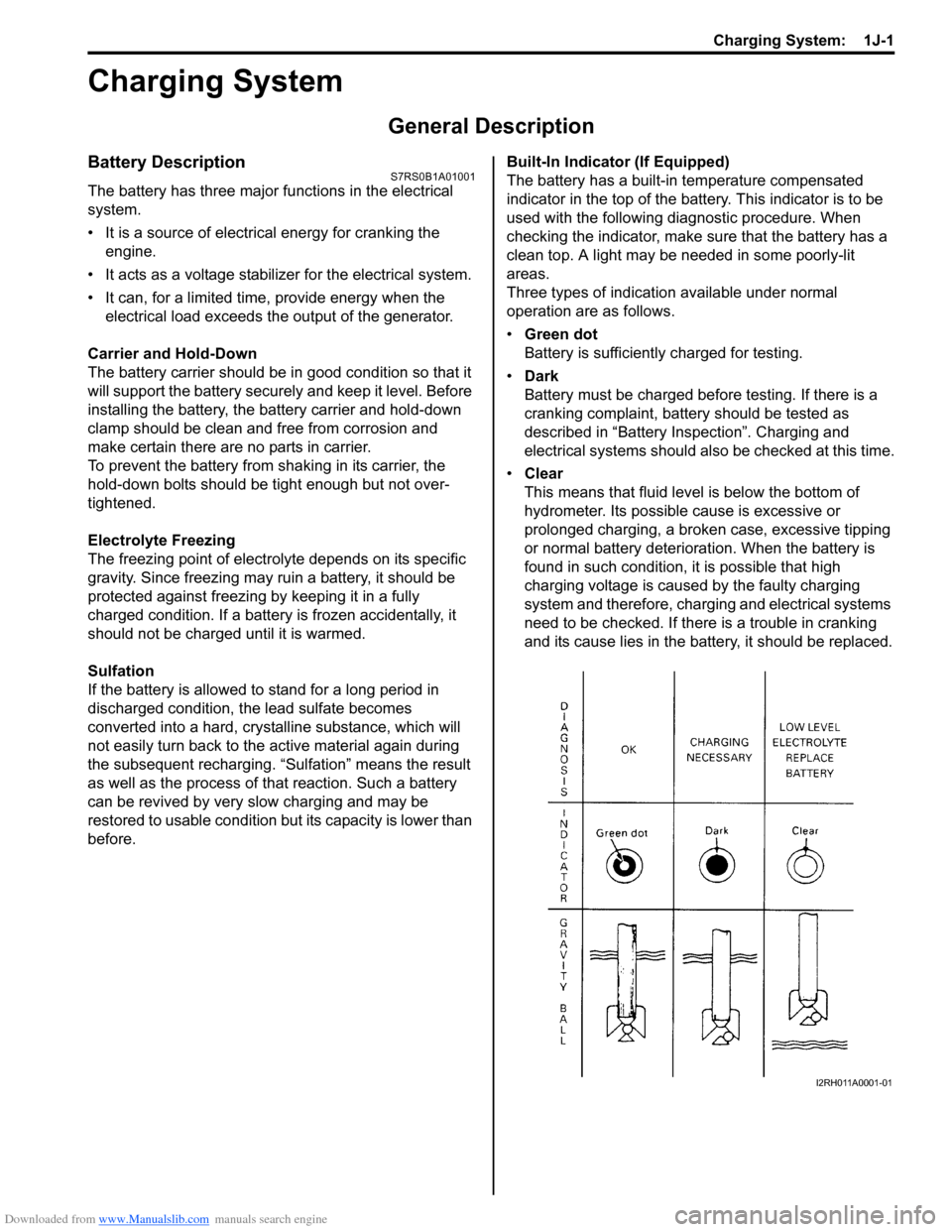
The battery has a built-in temperature compensated
indicator in the top of the battery. This indicator is to be
used with the following diagnostic procedure. When
checking the indicator, make sure that the battery has a
clean top. A light may be needed in some poorly-lit
areas.
Three types of indication available under normal
operation are as follows.
•
Green dot
Battery is sufficiently charged for testing.
• Dark
Battery must be charged before testing. If there is a
cranking complaint, battery should be tested as
described in “Battery Inspection”. Charging and
electrical systems should also be checked at this time.
• Clear
This means that fluid level is below the bottom of
hydrometer. Its possible cause is excessive or
prolonged charging, a broken case, excessive tipping
or normal battery deteriorat ion. When the battery is
found in such condition, it is possible that high
charging voltage is caused by the faulty charging
system and therefore, charging and electrical systems
need to be checked. If there is a trouble in cranking
and its cause lies in the battery, it should be replaced.
I2RH011A0001-01