2007 SUZUKI SWIFT Oul
[x] Cancel search: OulPage 327 of 1496
Downloaded from www.Manualslib.com manuals search engine Engine Mechanical: 1D-42
Cylinder Head InspectionS7RS0B1406027
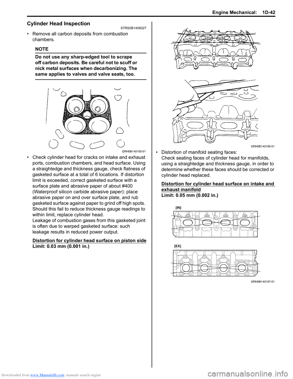
• Remove all carbon deposits from combustion chambers.
NOTE
Do not use any sharp-edged tool to scrape
off carbon deposits. Be careful not to scuff or
nick metal surfaces when decarbonizing. The
same applies to valves and valve seats, too.
• Check cylinder head for cracks on intake and exhaust ports, combustion chambers, and head surface. Using
a straightedge and thickness gauge, check flatness of
gasketed surface at a total of 6 locations. If distortion
limit is exceeded, correct gasketed surface with a
surface plate and abrasive paper of about #400
(Waterproof silicon carbide abrasive paper): place
abrasive paper on and over surface plate, and rub
gasketed surface against paper to grind off high spots.
Should this fail to reduce thickness gauge readings to
within limit, replace cylinder head.
Leakage of combustion gases from this gasketed joint
is often due to warped gasketed surface: such
leakage results in reduced power output.
Distortion for cylinder head surface on piston side
Limit: 0.03 mm (0.001 in.) • Distortion of manifold seating faces:
Check seating faces of cylinder head for manifolds,
using a straightedge and thickness gauge, in order to
determine whether these faces should be corrected or
cylinder head replaced.
Distortion for cylinder head surface on intake and
exhaust manifold
Limit: 0.05 mm (0.002 in.)
I2RH0B140105-01
I2RH0B140106-01
I2RH0B140107-01
Page 331 of 1496
Downloaded from www.Manualslib.com manuals search engine Engine Mechanical: 1D-46
Pistons, Piston Rings, Connecting Rods and
Cylinders Disassembly and Assembly
S7RS0B1406031
Disassembly1) Using piston ring expander, remove two compression rings (Top and 2nd) and oil ring from
piston.
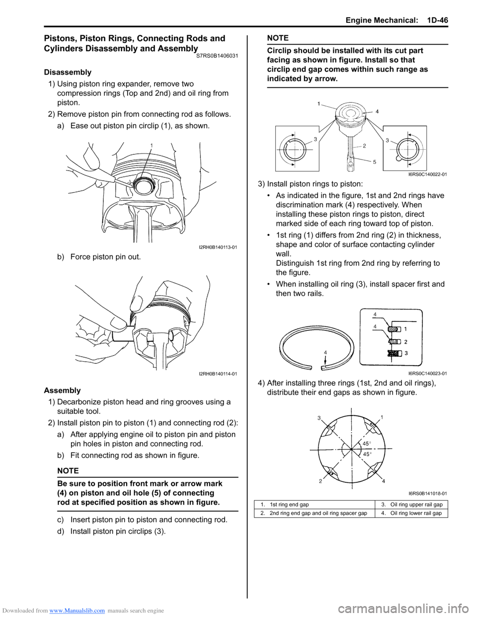
2) Remove piston pin from connecting rod as follows. a) Ease out piston pin circlip (1), as shown.
b) Force piston pin out.
Assembly 1) Decarbonize piston head and ring grooves using a suitable tool.
2) Install piston pin to piston (1) and connecting rod (2): a) After applying engine oil to piston pin and piston pin holes in piston and connecting rod.
b) Fit connecting rod as shown in figure.
NOTE
Be sure to position front mark or arrow mark
(4) on piston and oil hole (5) of connecting
rod at specified position as shown in figure.
c) Insert piston pin to piston and connecting rod.
d) Install piston pin circlips (3).
NOTE
Circlip should be installed with its cut part
facing as shown in figure. Install so that
circlip end gap comes within such range as
indicated by arrow.
3) Install piston rings to piston:
• As indicated in the figure, 1st and 2nd rings have discrimination mark (4) respectively. When
installing these piston rings to piston, direct
marked side of each ring toward top of piston.
• 1st ring (1) differs from 2nd ring (2) in thickness, shape and color of surface contacting cylinder
wall.
Distinguish 1st ring from 2nd ring by referring to
the figure.
• When installing oil ring (3), install spacer first and then two rails.
4) After installing three rings (1st, 2nd and oil rings), distribute their end gaps as shown in figure.
I2RH0B140113-01
I2RH0B140114-01
1. 1st ring end gap 3. Oil ring upper rail gap
2. 2nd ring end gap and oil ring spacer gap 4. Oil ring lower rail gap
I6RS0C140022-01
I6RS0C140023-01
I6RS0B141018-01
Page 332 of 1496
Downloaded from www.Manualslib.com manuals search engine 1D-47 Engine Mechanical:
Cylinders, Pistons and Piston Rings InspectionS7RS0B1406032
Cylinder
Visual inspection
Inspect cylinder walls for scratches, roughness or ridges
which indicate excessive wear. If cylinder bore is very
rough or deeply scratched, or ridged, rebore cylinder and
use over size piston.
Cylinder bore diameter, taper and out-of-round
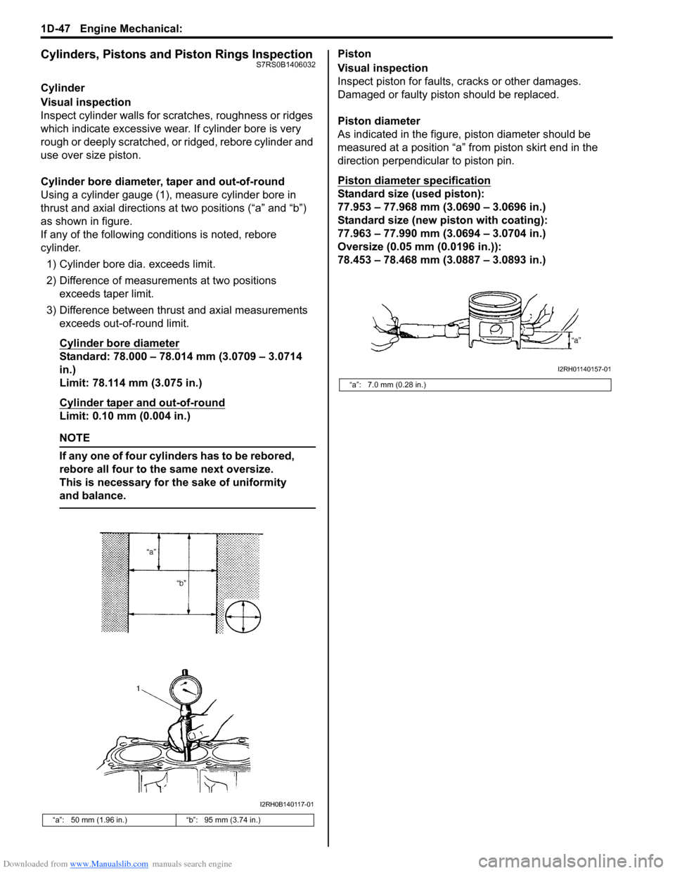
Using a cylinder gauge (1), measure cylinder bore in
thrust and axial directions at two positions (“a” and “b”)
as shown in figure.
If any of the following conditions is noted, rebore
cylinder.1) Cylinder bore dia. exceeds limit.
2) Difference of measurements at two positions exceeds taper limit.
3) Difference between thrust and axial measurements exceeds out-of-round limit.
Cylinder bore diameter
Standard: 78.000 – 78.014 mm (3.0709 – 3.0714
in.)
Limit: 78.114 mm (3.075 in.)
Cylinder taper and out-of-round
Limit: 0.10 mm (0.004 in.)
NOTE
If any one of four cylinders has to be rebored,
rebore all four to the same next oversize.
This is necessary for the sake of uniformity
and balance.
Piston
Visual inspection
Inspect piston for faults, cracks or other damages.
Damaged or faulty piston should be replaced.
Piston diameter
As indicated in the figure, piston diameter should be
measured at a position “a” from piston skirt end in the
direction perpendicular to piston pin.
Piston diameter specification
Standard size (used piston):
77.953 – 77.968 mm (3.0690 – 3.0696 in.)
Standard size (new piston with coating):
77.963 – 77.990 mm (3.0694 – 3.0704 in.)
Oversize (0.05 mm (0.0196 in.)):
78.453 – 78.468 mm (3.0887 – 3.0893 in.)
“a”: 50 mm (1.96 in.) “b”: 95 mm (3.74 in.)
I2RH0B140117-01
“a”: 7.0 mm (0.28 in.)
I2RH01140157-01
Page 333 of 1496
Downloaded from www.Manualslib.com manuals search engine Engine Mechanical: 1D-48
Piston clearance
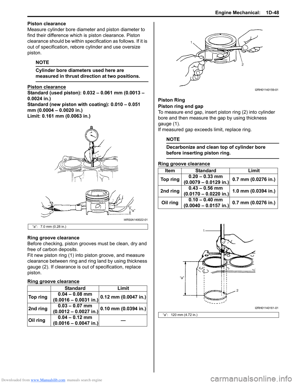
Measure cylinder bore diameter and piston diameter to
find their difference which is piston clearance. Piston
clearance should be within spec ification as follows. If it is
out of specification, rebore cylinder and use oversize
piston.
NOTE
Cylinder bore diameters used here are
measured in thrust direction at two positions.
Piston clearance
Standard (used piston): 0.032 – 0.061 mm (0.0013 –
0.0024 in.)
Standard (new piston with coating): 0.010 – 0.051
mm (0.0004 – 0.0020 in.)
Limit: 0.161 mm (0.0063 in.)
Ring groove clearance
Before checking, piston grooves must be clean, dry and
free of carbon deposits.
Fit new piston ring (1) into piston groove, and measure
clearance between ring and ring land by using thickness
gauge (2). If clearance is ou t of specification, replace
piston.
Ring groove clearance
Piston Ring
Piston ring end gap
To measure end gap, insert piston ring (2) into cylinder
bore and then measure the gap by using thickness
gauge (1).
If measured gap exceeds limit, replace ring.
NOTE
Decarbonize and clean top of cylinder bore
before inserting piston ring.
Ring groove clearance
“a”: 7.0 mm (0.28 in.)
Standard Limit
Top ring 0.04 – 0.08 mm
(0.0016 – 0.0031 in.) 0.12 mm (0.0047 in.)
2nd ring 0.03 – 0.07 mm
(0.0012 – 0.0027 in.) 0.10 mm (0.0394 in.)
Oil ring 0.04 – 0.12 mm
(0.0016 – 0.0047 in.) —
I4RS0A140022-01
Item Standard
Limit
To p r i n g 0.20 – 0.33 mm
(0.0079 – 0.0129 in.) 0.7 mm (0.0276 in.)
2nd ring 0.43 – 0.56 mm
(0.0170 – 0.0220 in.) 1.0 mm (0.0394 in.)
Oil ring 0.10 – 0.40 mm
(0.0040 – 0.0157 in.) 0.7 mm (0.0276 in.)
“a”: 120 mm (4.72 in.)
I2RH01140159-01
I2RH01140161-01
Page 347 of 1496

Downloaded from www.Manualslib.com manuals search engine Engine Mechanical: 1D-62
Undersize bearing (0.25 mm (0.0098 in.))
• 0.25 mm (0.0098 in.) undersize bearing is available, in five kinds varying in thickness.
To distinguish them, each bearing is painted in the following colors at such position as indicated in the figure.
Each color represents the following thickness at the center of bearing.
Undersize of crankshaft main bearing thickness
• If necessary, regrind crankshaft journal and sele ct undersize bearing to use with it as follows.
a. Regrind journal to the following finished diameter.
Finished journal diameter
51.7320 – 51.7500 mm (2.0367 – 2.0374 in.)
b. Using micrometer, measure regrind journal diameter. Measurement should be taken in two directions perpendicular to each other in order to check for out-of-round.
c. Using journal diameter measured above and alphabets stamped on cylinder block, select an undersize bearing
by referring to the following table.
Check bearing clearance with ne wly selected undersize bearing.
New undersize crankshaft main bearing specification
Color painted Bearing thickness
Red and Purple 2.117 – 2.121 mm (0.08335 – 0.08350 in.)
Red and Brown 2.120 – 2.124 mm (0.08347 – 0.08362 in.) Red and Green 2.123 – 2.127 mm (0.08359 – 0.08374 in.) Red and Black 2.126 – 2.130 mm (0.08371 – 0.08385 in.) Red only 2.129 – 2.133 mm (0.08382 – 0.08397 in.)
1. Paint
Measured journal diameter
51.7320 – 51.7379 mm (2.0367 – 2.0369 in.) 51.7380 – 51.7439 mm
(2.0370 – 2.0371 in.) 51.7440 – 51.7500 mm
(2.0372 – 2.0373 in.)
Alphabets stamped on cylinder block A (1) Red and Green Red and Brown Red and Purple
B (2) Red and Black Red and Green Red and Brown
C (3) Red only Red and Black Red and Green
Undersize bearing to be installed
I2RH01140192-01
I2RH0B140144-01
Page 364 of 1496

Downloaded from www.Manualslib.com manuals search engine 1F-1 Engine Cooling System:
Engine
Engine Cooling System
General Description
Cooling System DescriptionS7RS0B1601001
The cooling system consists of the radiator cap, radiator, coolant reservoir, hoses, water pump, cooling fan and
thermostat. The radiator is of tube-and-fin type.
Coolant DescriptionS7RS0B1601002
WARNING!
• Do not remove radiator cap to check engine coolant level; check coolant visually at the see-through coolant reservoir. Coolant should be added only to reservoir as necessary.
• As long as there is pressure in the cooling system, the temperature can be considerably higher than the boiling temperature of the solution in the radiator without causing the solution to boil. Removal
of the radiator cap while engine is hot and pressure is high will cause the solution to boil
instantaneously and possibly with explosive force, spewing the solution over engine, fenders and
person removing cap. If the solution contains flammable anti-freeze such as alcohol (not
recommended for use at any time), there is also the possibility of causing a serious fire.
• Check to make sure that engine coolant temperature is cold before removing any part of cooling system.
• Also be sure to disconnect negative cable from battery terminal before removing any part.
The coolant recovery system is standard. The coolant in the radiator expands with heat, and the coolant is overflowed
to the reservoir.
When the system cools down, the coolant is drawn back into the radiator.
The cooling system has be en filled with a quality coolant that is a 50/50 mixture of water and ethylene glycol
antifreeze.
This 50/50 mixture coolant solution provides freezing protection to –36 °C (–33 °F).
• Maintain cooling system freeze protection at –36 °C (–33 °F) to ensure protection against corrosion and loss of
coolant from boiling. This should be done even if freezing temperatures are not expected.
• Add ethylene glycol base coolant when coolant has to be added because of coolant loss or to provide added protection against freezing at temperature lower than –36 °C (–33 °F).
NOTE
• Alcohol or methanol base coolant or plain water alone should not be used in cooling system at any
time as damage to cooling system could occur.
• Coolant must be mixed with deminerated water or distilled water.
Anti-freeze proportioning table
For M/T model For A/T model
Freezing temperature °
C –36 –36
° F –33 –33
Anti-freeze / Anti-corrosion coolant concentration % 50 50
Ratio of compound to cooling water ltr. 3.10/3.10 3.05/3.05
US pt. 6.55/6.55 6.44/6.44
Imp pt. 5.46/5.46 5.37/5.37
Page 369 of 1496
Downloaded from www.Manualslib.com manuals search engine Engine Cooling System: 1F-6
Coolant Level CheckS7RS0B1606002
WARNING!
To help avoid danger of being burned, do not
remove radiator cap while engine and
radiator are still hot. Scalding fluid and steam
can be blown out under pressure if radiator
cap is taken off too soon.
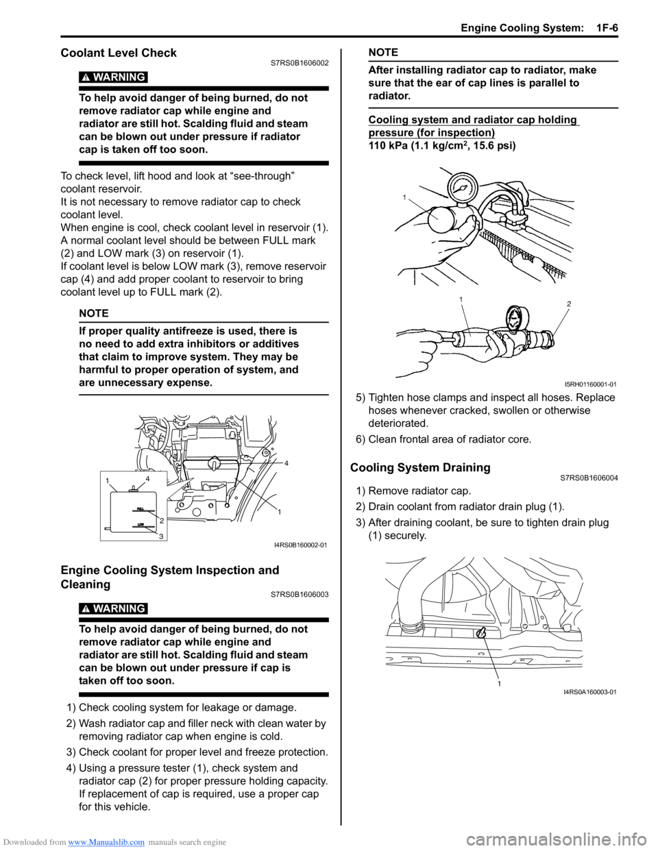
To check level, lift hood and look at “see-through”
coolant reservoir.
It is not necessary to remove radiator cap to check
coolant level.
When engine is cool, check coolant level in reservoir (1).
A normal coolant level should be between FULL mark
(2) and LOW mark (3) on reservoir (1).
If coolant level is below LOW mark (3), remove reservoir
cap (4) and add proper coolant to reservoir to bring
coolant level up to FULL mark (2).
NOTE
If proper quality antifreeze is used, there is
no need to add extra inhibitors or additives
that claim to improve system. They may be
harmful to proper operation of system, and
are unnecessary expense.
Engine Cooling System Inspection and
Cleaning
S7RS0B1606003
WARNING!
To help avoid danger of being burned, do not
remove radiator cap while engine and
radiator are still hot. Scalding fluid and steam
can be blown out under pressure if cap is
taken off too soon.
1) Check cooling system for leakage or damage.
2) Wash radiator cap and fille r neck with clean water by
removing radiator cap when engine is cold.
3) Check coolant for proper level and freeze protection.
4) Using a pressure tester (1), check system and radiator cap (2) for proper pressure holding capacity.
If replacement of cap is required, use a proper cap
for this vehicle.
NOTE
After installing radiator cap to radiator, make
sure that the ear of cap lines is parallel to
radiator.
Cooling system and radiator cap holding
pressure (for inspection)
110 kPa (1.1 kg/cm2, 15.6 psi)
5) Tighten hose clamps and inspect all hoses. Replace hoses whenever cracked, swollen or otherwise
deteriorated.
6) Clean frontal area of radiator core.
Cooling System DrainingS7RS0B1606004
1) Remove radiator cap.
2) Drain coolant from radiator drain plug (1).
3) After draining coolant, be sure to tighten drain plug (1) securely.
1
4
1
3
2
4
I4RS0B160002-01
I5RH01160001-01
1I4RS0A160003-01
Page 371 of 1496
Downloaded from www.Manualslib.com manuals search engine Engine Cooling System: 1F-8
Thermostat Removal and InstallationS7RS0B1606007
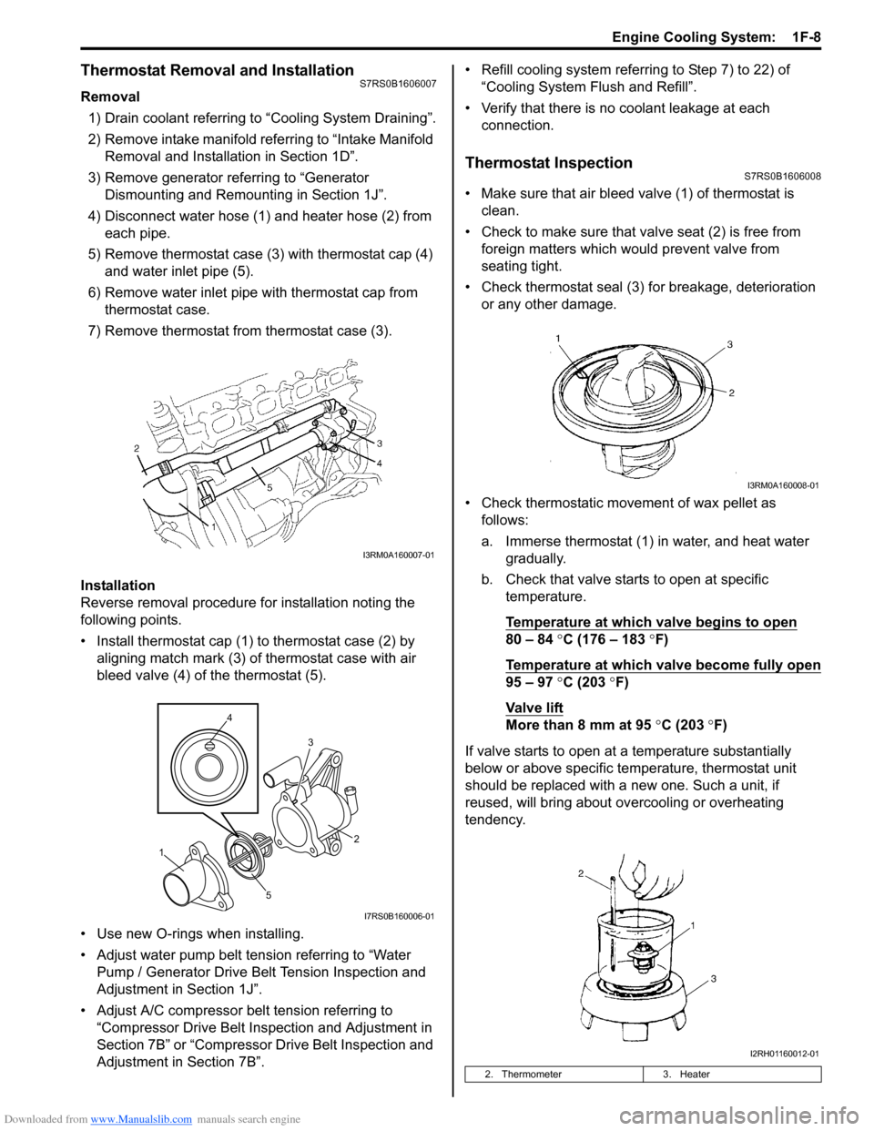
Removal1) Drain coolant referring to “Cooling System Draining”.
2) Remove intake manifold referring to “Intake Manifold Removal and Installa tion in Section 1D”.
3) Remove generator referring to “Generator Dismounting and Remounting in Section 1J”.
4) Disconnect water hose (1) and heater hose (2) from each pipe.
5) Remove thermostat case (3) with thermostat cap (4)
and water inlet pipe (5).
6) Remove water inlet pipe with thermostat cap from thermostat case.
7) Remove thermostat from thermostat case (3).
Installation
Reverse removal procedure for installation noting the
following points.
• Install thermostat cap (1) to thermostat case (2) by aligning match mark (3) of thermostat case with air
bleed valve (4) of the thermostat (5).
• Use new O-rings when installing.
• Adjust water pump belt tension referring to “Water Pump / Generator Drive Belt Tension Inspection and
Adjustment in Section 1J”.
• Adjust A/C compressor belt tension referring to “Compressor Drive Belt Inspection and Adjustment in
Section 7B” or “Compressor Drive Belt Inspection and
Adjustment in Section 7B”. • Refill cooling system referrin
g to Step 7) to 22) of
“Cooling System Flush and Refill”.
• Verify that there is no coolant leakage at each connection.
Thermostat InspectionS7RS0B1606008
• Make sure that air bleed valve (1) of thermostat is clean.
• Check to make sure that va lve seat (2) is free from
foreign matters which would prevent valve from
seating tight.
• Check thermostat seal (3) for breakage, deterioration or any other damage.
• Check thermostatic movement of wax pellet as follows:
a. Immerse thermostat (1) in water, and heat water gradually.
b. Check that valve starts to open at specific temperature.
Temperature at which valve begins to open
80 – 84 °C (176 – 183 °F)
Temperature at which valve become fully open
95 – 97 °C (203 °F)
Va l v e l i ft
More than 8 mm at 95 °C (203 ° F)
If valve starts to open at a temperature substantially
below or above specific temperature, thermostat unit
should be replaced with a new one. Such a unit, if
reused, will bring about ov ercooling or overheating
tendency.
I3RM0A160007-01
4
5 3
1 2
I7RS0B160006-01
2. Thermometer
3. Heater
I3RM0A160008-01
I2RH01160012-01