2007 SUZUKI SWIFT Drive
[x] Cancel search: DrivePage 249 of 1496
Downloaded from www.Manualslib.com manuals search engine Engine General Information and Diagnosis: 1A-199
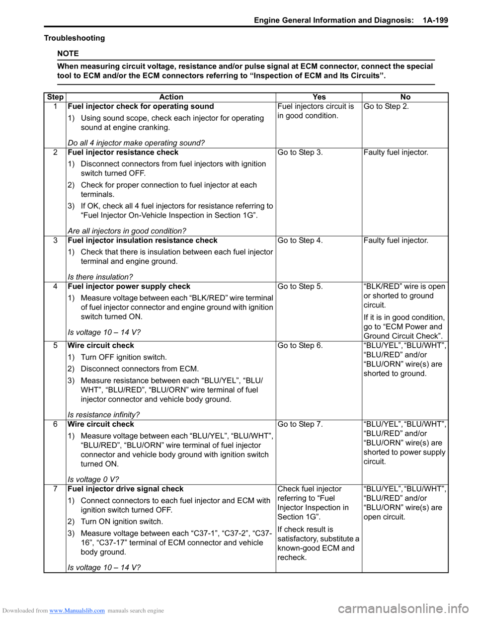
Troubleshooting
NOTE
When measuring circuit voltage, resistance and/or pulse signal at ECM connector, connect the special
tool to ECM and/or the ECM connectors referri ng to “Inspection of ECM and Its Circuits”.
StepAction YesNo
1 Fuel injector check for operating sound
1) Using sound scope, check each injector for operating
sound at engine cranking.
Do all 4 injector ma ke operating sound? Fuel injectors circuit is
in good condition.
Go to Step 2.
2 Fuel injector resistance check
1) Disconnect connectors from fuel injectors with ignition
switch turned OFF.
2) Check for proper connection to fuel injector at each terminals.
3) If OK, check all 4 fuel inject ors for resistance referring to
“Fuel Injector On-Vehicle Inspection in Section 1G”.
Are all injectors in good condition? Go to Step 3.
Faulty fuel injector.
3 Fuel injector insulation resistance check
1) Check that there is insulation between each fuel injector
terminal and engine ground.
Is there insulation? Go to Step 4.
Faulty fuel injector.
4 Fuel injector power supply check
1) Measure voltage between each “BLK/RED” wire terminal
of fuel injector connector and engine ground with ignition
switch turned ON.
Is voltage 10 – 14 V? Go to Step 5.
“BLK/RED” wire is open
or shorted to ground
circuit.
If it is in good condition,
go to “ECM Power and
Ground Circuit Check”.
5 Wire circuit check
1) Turn OFF ignition switch.
2) Disconnect connectors from ECM.
3) Measure resistance between each “BLU/YEL”, “BLU/
WHT”, “BLU/RED”, “BLU/ORN” wire terminal of fuel
injector connector and vehicle body ground.
Is resistance infinity? Go to Step 6.
“BLU/YEL”, “BLU/WHT”,
“BLU/RED” and/or
“BLU/ORN” wire(s) are
shorted to ground.
6 Wire circuit check
1) Measure voltage between each “BLU/YEL”, “BLU/WHT”,
“BLU/RED”, “BLU/ORN” wire terminal of fuel injector
connector and vehicle body ground with ignition switch
turned ON.
Is voltage 0 V? Go to Step 7.
“BLU/YEL”, “BLU/WHT”,
“BLU/RED” and/or
“BLU/ORN” wire(s) are
shorted to power supply
circuit.
7 Fuel injector drive signal check
1) Connect connectors to each fuel injector and ECM with
ignition switch turned OFF.
2) Turn ON ignition switch.
3) Measure voltage between each “C37-1”, “C37-2”, “C37- 16”, “C37-17” terminal of ECM connector and vehicle
body ground.
Is voltage 10 – 14 V? Check fuel injector
referring to “Fuel
Injector Inspection in
Section 1G”.
If check result is
satisfactory, substitute a
known-good ECM and
recheck.
“BLU/YEL”, “BLU/WHT”,
“BLU/RED” and/or
“BLU/ORN” wire(s) are
open circuit.
Page 251 of 1496

Downloaded from www.Manualslib.com manuals search engine Engine General Information and Diagnosis: 1A-201
Troubleshooting
NOTE
When measuring circuit voltage, resistance and/or pulse signal at ECM connector, connect the special
tool to ECM and/or the ECM connectors referri ng to “Inspection of ECM and Its Circuits”.
StepAction YesNo
1 Fuel pump control system check for operation
Is fuel pump heard to operate 2 sec. after ignition switch is
turned ON? Fuel pump circuit is in
good condition.
Go to Step 2.
2 Fuel pump relay po wer supply check
1) Disconnect fuel pump relay from individual circuit fuse box No.1 with ignition switch turned OFF.
2) Check for proper connection to fuel pump relay at each terminal.
3) If OK, turn ON ignition switch, measure voltage between “BLK/WHT” wire terminal of fuel pump relay connector
and engine ground.
Is voltage 10 – 14 V? Go to Step 3.
“BLK/WHT” wire is open
or shorted to ground
circuit.
3 Fuel pump relay po wer supply check
1) Turn ON ignition switch, measure voltage between “BLK/ RED” wire terminal of fuel pump relay connector and
engine ground.
Is voltage 10 – 14 V? Go to Step 4.
“BLK/RED” wire is open
circuit.
4 Fuel pump relay check
1) Check fuel pump relay referring to “Main Relay, Fuel
Pump Relay and Starting Moto r Control Relay Inspection
in Section 1C”.
Is relay in good condition? Go to Step 5.
Faulty relay.
5 Fuel pump relay drive signal check
1) Connect fuel pump relay to individual circuit fuse box
No.1.
2) Connect voltmeter between “E23-15” terminal of ECM connector and vehicle body ground.
3) Measure voltage 2 second after ignition switch is turned ON.
Is voltage 10 – 14 V? Go to Step 6.
“GRN/WHT” wire is
open circuit or shorted
to ground circuit.
I2RH01110132-01
Page 252 of 1496

Downloaded from www.Manualslib.com manuals search engine 1A-202 Engine General Information and Diagnosis:
6Fuel pump relay drive signal check
1) Measure voltage within 2 second after ignition switch is
turned ON.
Is voltage 0 – 1 V? Go to Step 7. Substitute a known-
good ECM and recheck.
7 Wire circuit check
1) Turn OFF ignition switch.
2) Detach fuel tank referring to “Fuel Tank Removal and
Installation in Section 1G”.
3) Disconnect connector from fuel pump.
4) Measure resistance between “PNK” wire terminal of fuel pump connector and vehicle body ground.
Is resistance infinity? Go to Step 8. “PNK” wire is shorted to
ground.
8 Fuel pump circuit check
1) Connect service wire between “E23-15” terminal of ECM
connector and vehicle body ground.
2) Turn ON ignition switch, measure voltage between “PNK” terminal at fuel pump connector and vehicle body
ground.
Is voltage 10 – 14 V? Go to Step 9. “PNK” wire is open
circuit.
9 Fuel pump circuit check
1) Turn OFF ignition switch.
2) Measure resistance between “BLK” wire terminal at fuel
pump connector and vehicle body ground.
Is resistance less than 5
Ω? Faulty fuel pump. “BLK” wire is open
circuit.
Step Action Yes No
Page 257 of 1496

Downloaded from www.Manualslib.com manuals search engine Engine General Information and Diagnosis: 1A-207
6A/C evaporator outlet air temp. sensor check
1) Disconnect connectors from ECM with ignition switch
turned OFF.
2) Check for proper connection to “E23-57” and “E23-54” wire terminals of ECM connector.
3) If OK, measure resistance between “E23-57” and “E23- 54” wire terminals of ECM connector.
Evaporator temp. sensor resistance
At 0 °C: 6.3 – 6.9 k Ω
At 25 °C: 1.8 – 2.2 k Ω
Is resistance within specification? Go to Step 7. Faulty A/C evaporator
outlet air temp. sensor
or its circuit.
7 DTC check of A/C refrigerant pressure sensor circuit
1) Connect scan tool to DLC with ignition switch turned
OFF.
2) Turn ON ignition switch.
3) Check ECM for DTC of A/C refrigerant pressure sensor circuit.
Is there DTC P0532 or DTC P0533? Go to applicable DTC
diag. flow.
Go to Step 8.
8 A/C refrigerant pressure sensor voltage check
1) Check A/C refrigerant pressure sensor voltage referring
to “Inspection of ECM and Its Circuits”.
Is voltage within specified value? Go to Step 9. Check amount of
refrigerant. If OK,
replace A/C refrigerant
pressure sensor.
9 Radiator cooling fan check
1) Check radiator cooling fan referring to “Radiator Cooling
Fan Motor On-Vehicle Inspection in Section 1F”.
Is check result satisfactory? Radiator cooling fan
drive circuit malfunction.
If circuit is OK, go to
St ep 6 .
Replace radiator cooling
fan motor.
10 A/C compressor control system check
Is A/C compressor started when A/C and blower speed
selector switch are turned ON with engine running? A/C system is in good
condition.
Go to Step 11.
Step Action Yes No
7
6
5
4
3
2
1
10
20 30
40 50
0
10
2030
60 70 80
ResistanceTemperatureI3RB0A110053-01
Page 258 of 1496
Downloaded from www.Manualslib.com manuals search engine 1A-208 Engine General Information and Diagnosis:
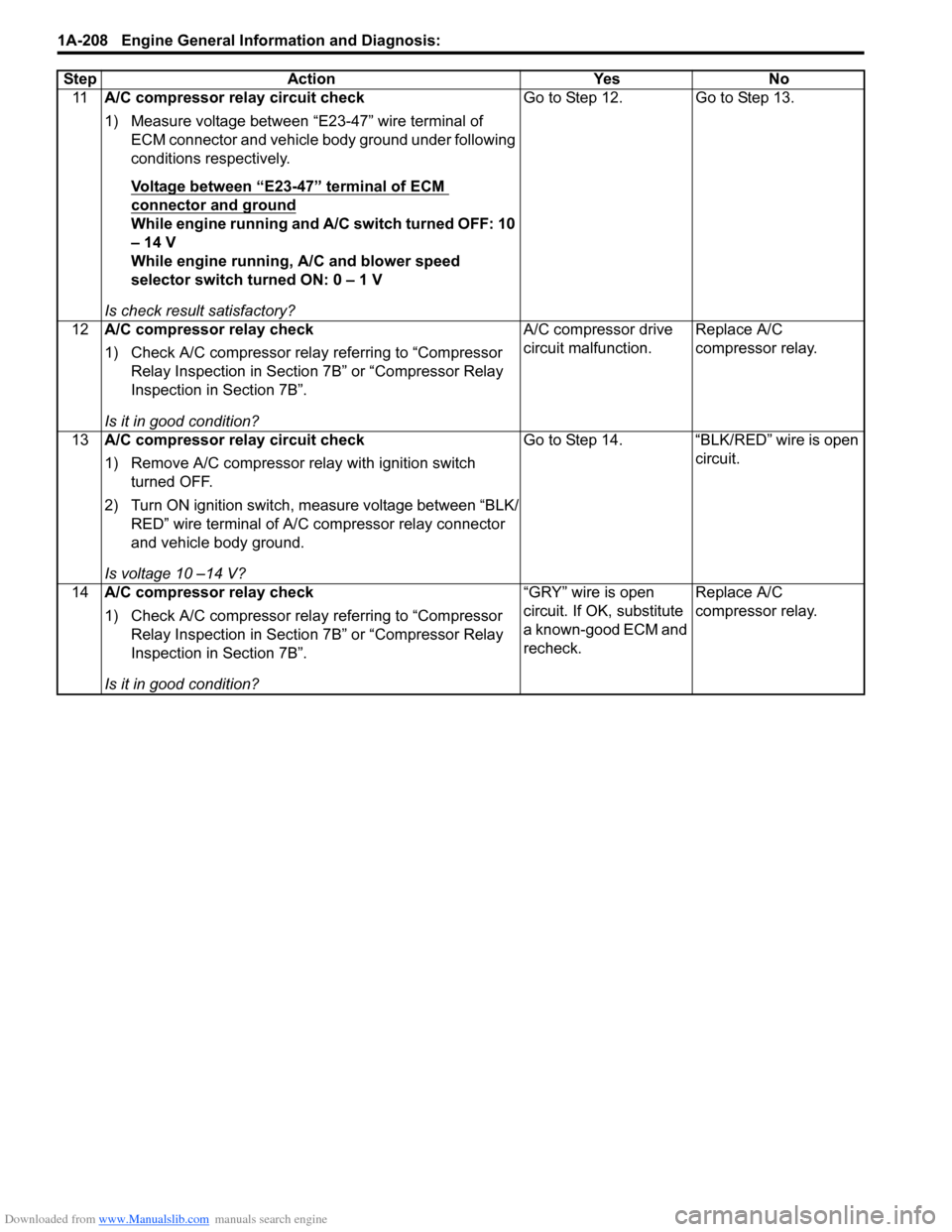
11A/C compressor relay circuit check
1) Measure voltage between “E23-47” wire terminal of
ECM connector and vehicle body ground under following
conditions respectively.
Voltage between “E23-47” terminal of ECM
connector and ground
While engine running and A/C switch turned OFF: 10
– 14 V
While engine running, A/C and blower speed
selector switch turned ON: 0 – 1 V
Is check result satisfactory? Go to Step 12. Go to Step 13.
12 A/C compressor relay check
1) Check A/C compressor rela y referring to “Compressor
Relay Inspection in Sectio n 7B” or “Compressor Relay
Inspection in Section 7B”.
Is it in good condition? A/C compressor drive
circuit malfunction.
Replace A/C
compressor relay.
13 A/C compressor relay circuit check
1) Remove A/C compressor re lay with ignition switch
turned OFF.
2) Turn ON ignition switch, measure voltage between “BLK/ RED” wire terminal of A/C compressor relay connector
and vehicle body ground.
Is voltage 10 –14 V? Go to Step 14. “BLK/RED” wire is open
circuit.
14 A/C compressor relay check
1) Check A/C compressor rela y referring to “Compressor
Relay Inspection in Sectio n 7B” or “Compressor Relay
Inspection in Section 7B”.
Is it in good condition? “GRY” wire is open
circuit. If OK, substitute
a known-good ECM and
recheck.
Replace A/C
compressor relay.
Step Action Yes No
Page 266 of 1496
Downloaded from www.Manualslib.com manuals search engine 1A-216 Engine General Information and Diagnosis:
Repair Instructions
Idle Speed and IAC Throttle Valve Opening
Inspection
S7RS0B1106001
Before idle speed check, make sure of the following.
• Lead wires and hoses of electronic fuel injection and engine and emission control systems are connected
securely.
• Valve lash is checked according to maintenance schedule.
• Ignition timing is within specification.
• All accessories (wipers, heater, lights, A/C, etc.) are out of service.
• Air cleaner has been properly installed and is in good condition.
• No abnormal air drawn in from air intake system.
After all items are confirmed, check idle speed and IAC
duty as follows.
NOTE
Before starting engine, place transmission
gear shift lever in “Neutral” (shift selector
lever to “P” range for A/T vehicle), and set
parking brake and block drive wheels.
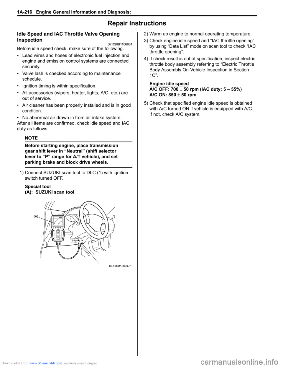
1) Connect SUZUKI scan tool to DLC (1) with ignition
switch turned OFF.
Special tool
(A): SUZUKI scan tool 2) Warm up engine to normal operating temperature.
3) Check engine idle speed and “IAC throttle opening”
by using “Data List” mode on scan tool to check “IAC
throttle opening”.
4) If check result is out of sp ecification, inspect electric
throttle body assembly referring to “Electric Throttle
Body Assembly On-Vehicle Inspection in Section
1C”.
Engine idle speed
A/C OFF: 700 ± 50 rpm (IAC duty: 5 – 55%)
A/C ON: 850 ± 50 rpm
5) Check that specified engine idle speed is obtained with A/C turned ON if vehi cle is equipped with A/C.
If not, check A/C system.
(A)
1
I4RS0B110093-01
Page 281 of 1496
Downloaded from www.Manualslib.com manuals search engine Engine Electrical Devices: 1C-9
CKP Sensor Removal and InstallationS7RS0B1306014
Removal1) Disconnect negative (–) cable at battery.
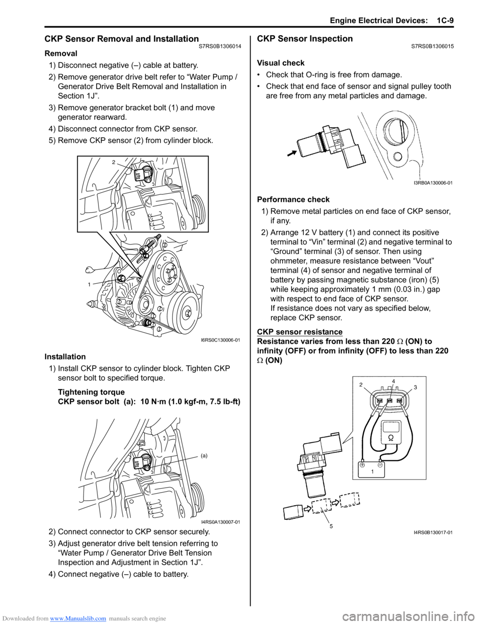
2) Remove generator drive belt refer to “Water Pump / Generator Drive Belt Remo val and Installation in
Section 1J”.
3) Remove generator bracket bolt (1) and move generator rearward.
4) Disconnect connector from CKP sensor.
5) Remove CKP sensor (2) from cylinder block.
Installation 1) Install CKP sensor to cylinder block. Tighten CKP sensor bolt to specified torque.
Tightening torque
CKP sensor bolt (a): 10 N·m (1.0 kgf-m, 7.5 lb-ft)
2) Connect connector to CKP sensor securely.
3) Adjust generator drive belt tension referring to “Water Pump / Generator Drive Belt Tension
Inspection and Adjustment in Section 1J”.
4) Connect negative (–) cable to battery.
CKP Sensor InspectionS7RS0B1306015
Visual check
• Check that O-ring is free from damage.
• Check that end face of sensor and signal pulley tooth are free from any metal particles and damage.
Performance check 1) Remove metal particles on end face of CKP sensor, if any.
2) Arrange 12 V battery (1) and connect its positive terminal to “Vin” terminal (2) and negative terminal to
“Ground” terminal (3) of sensor. Then using
ohmmeter, measure resistance between “Vout”
terminal (4) of sensor and negative terminal of
battery by passing magnetic substance (iron) (5)
while keeping approximately 1 mm (0.03 in.) gap
with respect to end face of CKP sensor.
If resistance does not vary as specified below,
replace CKP sensor.
CKP sensor resistance
Resistance varies from less than 220 Ω (ON) to
infinity (OFF) or from infinity (OFF) to less than 220
Ω (ON)
2
1
I6RS0C130006-01
(a)
I4RS0A130007-01
I3RB0A130006-01
I4RS0B130017-01
Page 282 of 1496
Downloaded from www.Manualslib.com manuals search engine 1C-10 Engine Electrical Devices:
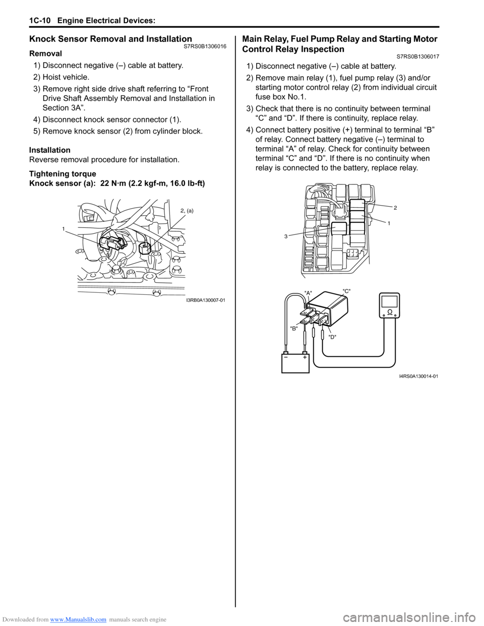
Knock Sensor Removal and InstallationS7RS0B1306016
Removal1) Disconnect negative (–) cable at battery.
2) Hoist vehicle.
3) Remove right side drive shaft referring to “Front Drive Shaft Assembly Removal and Installation in
Section 3A”.
4) Disconnect knock sensor connector (1).
5) Remove knock sensor (2) from cylinder block.
Installation
Reverse removal procedure for installation.
Tightening torque
Knock sensor (a): 22 N· m (2.2 kgf-m, 16.0 lb-ft)
Main Relay, Fuel Pump Relay and Starting Motor
Control Relay Inspection
S7RS0B1306017
1) Disconnect negative (–) cable at battery.
2) Remove main relay (1), fuel pump relay (3) and/or
starting motor control relay (2) from individual circuit
fuse box No.1.
3) Check that there is no continuity between terminal “C” and “D”. If there is continuity, replace relay.
4) Connect battery positive (+ ) terminal to terminal “B”
of relay. Connect battery negative (–) terminal to
terminal “A” of relay. Ch eck for continuity between
terminal “C” and “D”. If t here is no continuity when
relay is connected to the battery, replace relay.
1 2, (a)
I3RB0A130007-01
"D"
"B" "A"
"C"
2
1
3
I4RS0A130014-01