2007 SUZUKI SWIFT Drive
[x] Cancel search: DrivePage 87 of 1496
Downloaded from www.Manualslib.com manuals search engine Engine General Information and Diagnosis: 1A-37
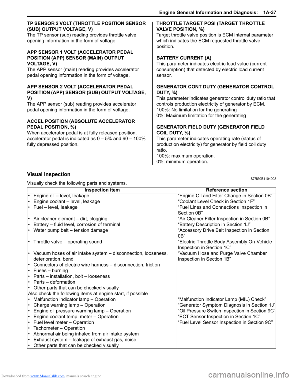
TP SENSOR 2 VOLT (THROTTLE POSITION SENSOR
(SUB) OUTPUT VOLTAGE, V)
The TP sensor (sub) reading provides throttle valve
opening information in the form of voltage.
APP SENSOR 1 VOLT (ACCELERATOR PEDAL
POSITION (APP) SENSOR (MAIN) OUTPUT
VOLTAGE, V)
The APP sensor (main) read ing provides accelerator
pedal opening information in the form of voltage.
APP SENSOR 2 VOLT (ACCELERATOR PEDAL
POSITION (APP) SENSOR (S UB) OUTPUT VOLTAGE,
V)
The APP sensor (sub) reading provides accelerator
pedal opening information in the form of voltage.
ACCEL POSITION (ABSOLUTE ACCELERATOR
PEDAL POSITION, %)
When accelerator pedal is at fully released position,
accelerator pedal is indicated as 0 – 5% and 90 – 100%
fully depressed position. THROTTLE TARGET POSI (TARGET THROTTLE
VALVE POSITION, %)
Target throttle valve position is ECM internal parameter
which indicates the ECM requested throttle valve
position.
BATTERY CURRENT (A)
This parameter indicates elec
tric load value (current
consumption) that detected by electric load current
sensor.
GENERATOR CONT DUTY (GENERATOR CONTROL
DUTY, %)
This parameter indicates generator control duty ratio that
controls production electricity of generator by ECM.
100%: No limitation for the generating
0%: Maximum limitation for the generating
GENERATOR FIELD DUTY (GENERATOR FIELD
COIL DUTY, %)
This parameter indicates ope rating rate (status of
production electricity) for gen erator by field coil duty
ratio.
100%: maximum operation.
0%: minimum operation.
Visual InspectionS7RS0B1104008
Visually check the following parts and systems.
Inspection item Reference section
• Engine oil – level, leakage “Engine Oil and Filter Change in Section 0B”
• Engine coolant – level, leakage “Co olant Level Check in Section 1F”
• Fuel – level, leakage “Fuel Lines and Connections Inspection in Section 0B”
• Air cleaner element – dirt, clogging “Air Cleaner Filter Inspection in Section 0B”
• Battery – fluid level, corrosion of terminal “Battery Description in Section 1J”
• Water pump belt – tension damage “Accessory Drive Belt Inspection in Section 0B”
• Throttle valve – operating sound “Electric Throttle Body Assembly On-Vehicle Inspection in Section 1C”
• Vacuum hoses of air intake system – disconnection, looseness,
deterioration, bend “Vacuum Hose and Purge Valve Chamber
Inspection in Section 1B”
• Connectors of electric wire harness – disconnection, friction
• Fuses – burning
• Parts – installation, bolt – looseness
• Parts – deformation
• Other parts that can be checked visually
Also check the following items at engine start, if possible
• Malfunction indicator lamp – Operation “Malfunction Indicator Lamp (MIL) Check”
• Charge warning lamp – Operation “Genera tor Symptom Diagnosis in Section 1J”
• Engine oil pressure warning lamp – Operation “O il Pressure Switch Inspection in Section 9C”
• Engine coolant temp. meter – Operation “ECT Sensor Inspection in Section 1C”
• Fuel level meter – Operation “Fuel Level Sensor Inspection in Section 9C”
• Tachometer – Operation
• Abnormal air being inhaled from air intake system
• Exhaust system – leakage of exhaust gas, noise
• Other parts that can be checked visually
Page 102 of 1496
Downloaded from www.Manualslib.com manuals search engine 1A-52 Engine General Information and Diagnosis:
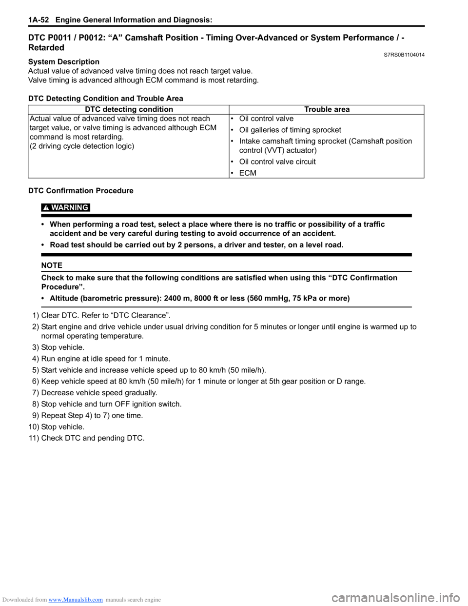
DTC P0011 / P0012: “A” Camshaft Position - Timing Over-Advanced or System Performance / -
Retarded
S7RS0B1104014
System Description
Actual value of advanced valve timing does not reach target value.
Valve timing is advanced although ECM command is most retarding.
DTC Detecting Condition and Trouble Area
DTC Confirmation Procedure
WARNING!
• When performing a road test, select a place where there is no traffic or possibility of a traffic accident and be very careful during testing to avoid occurrence of an accident.
• Road test should be carried out by 2 persons, a driver and tester, on a level road.
NOTE
Check to make sure that the following conditions are satisfied when using this “DTC Confirmation
Procedure”.
• Altitude (barometric pressure): 2400 m, 8000 ft or less (560 mmHg, 75 kPa or more)
1) Clear DTC. Refer to “DTC Clearance”.
2) Start engine and drive vehicle under usual driving condition for 5 minutes or longer until engine is warmed up to normal operating temperature.
3) Stop vehicle.
4) Run engine at idle speed for 1 minute.
5) Start vehicle and increase vehicle speed up to 80 km/h (50 mile/h).
6) Keep vehicle speed at 80 km/h (50 mile/h) for 1 minute or longer at 5th gear position or D range.
7) Decrease vehicle speed gradually.
8) Stop vehicle and turn OFF ignition switch.
9) Repeat Step 4) to 7) one time.
10) Stop vehicle. 11) Check DTC and pending DTC. DTC detecting condition
Trouble area
Actual value of advanced valve timing does not reach
target value, or valve timi ng is advanced although ECM
command is most retarding.
(2 driving cycle detection logic) • Oil control valve
• Oil galleries of timing sprocket
• Intake camshaft timing sprocket (Camshaft position
control (VVT) actuator)
• Oil control valve circuit
•ECM
Page 103 of 1496
Downloaded from www.Manualslib.com manuals search engine Engine General Information and Diagnosis: 1A-53
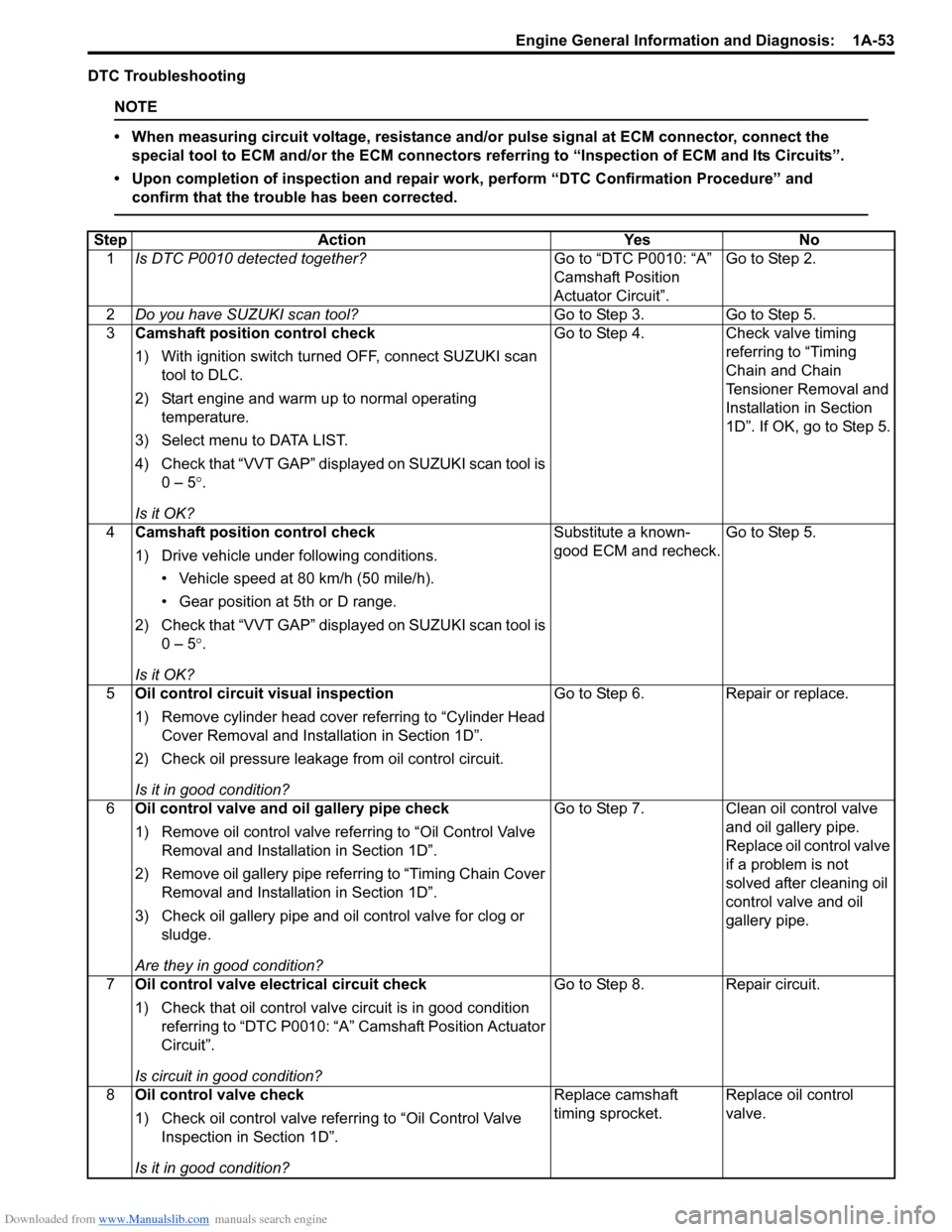
DTC Troubleshooting
NOTE
• When measuring circuit voltage, resistance and/or pulse signal at ECM connector, connect the
special tool to ECM and/or the ECM connectors re ferring to “Inspection of ECM and Its Circuits”.
• Upon completion of inspection and repair work, perform “DTC Confirmation Procedure” and confirm that the trouble has been corrected.
Step Action YesNo
1 Is DTC P0010 detected together? Go to “DTC P0010: “A”
Camshaft Position
Actuator Circuit”.Go to Step 2.
2 Do you have SUZUKI scan tool? Go to Step 3.Go to Step 5.
3 Camshaft position control check
1) With ignition switch turned OFF, connect SUZUKI scan
tool to DLC.
2) Start engine and warm up to normal operating temperature.
3) Select menu to DATA LIST.
4) Check that “VVT GAP” displayed on SUZUKI scan tool is 0 – 5 °.
Is it OK? Go to Step 4.
Check valve timing
referring to “Timing
Chain and Chain
Tensioner Removal and
Installation in Section
1D”. If OK, go to Step 5.
4 Camshaft position control check
1) Drive vehicle under following conditions.
• Vehicle speed at 80 km/h (50 mile/h).
• Gear position at 5th or D range.
2) Check that “VVT GAP” displayed on SUZUKI scan tool is 0 – 5 °.
Is it OK? Substitute a known-
good ECM and recheck.
Go to Step 5.
5 Oil control circuit visual inspection
1) Remove cylinder head cover referring to “Cylinder Head
Cover Removal and Insta llation in Section 1D”.
2) Check oil pressure leakage from oil control circuit.
Is it in good condition? Go to Step 6.
Repair or replace.
6 Oil control valve and oil gallery pipe check
1) Remove oil control valve re ferring to “Oil Control Valve
Removal and Installation in Section 1D”.
2) Remove oil gallery pipe refe rring to “Timing Chain Cover
Removal and Installation in Section 1D”.
3) Check oil gallery pipe and o il control valve for clog or
sludge.
Are they in good condition? Go to Step 7.
Clean oil control valve
and oil gallery pipe.
Replace oil control valve
if a problem is not
solved after cleaning oil
control valve and oil
gallery pipe.
7 Oil control valve electrical circuit check
1) Check that oil control valve circuit is in good condition
referring to “DTC P0010: “A” Camshaft Position Actuator
Circuit”.
Is circuit in good condition? Go to Step 8.
Repair circuit.
8 Oil control valve check
1) Check oil control valve refe rring to “Oil Control Valve
Inspection in Section 1D”.
Is it in good condition? Replace camshaft
timing sprocket.
Replace oil control
valve.
Page 105 of 1496
Downloaded from www.Manualslib.com manuals search engine Engine General Information and Diagnosis: 1A-55
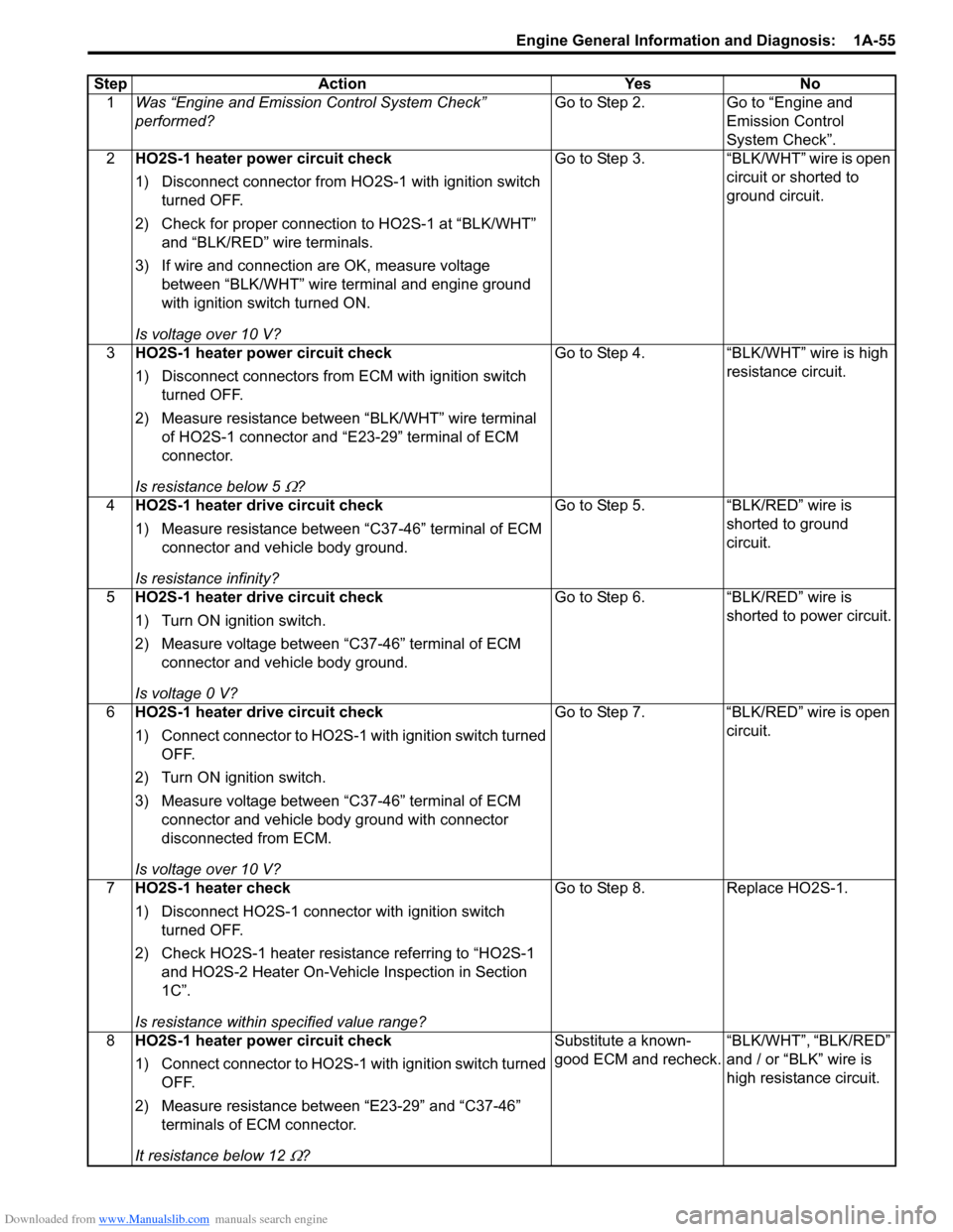
StepAction YesNo
1 Was “Engine and Emission Control System Check”
performed? Go to Step 2.
Go to “Engine and
Emission Control
System Check”.
2 HO2S-1 heater power circuit check
1) Disconnect connector from HO 2S-1 with ignition switch
turned OFF.
2) Check for proper connection to HO2S-1 at “BLK/WHT” and “BLK/RED” wire terminals.
3) If wire and connection are OK, measure voltage between “BLK/WHT” wire terminal and engine ground
with ignition switch turned ON.
Is voltage over 10 V? Go to Step 3.
“BLK/WHT” wire is open
circuit or shorted to
ground circuit.
3 HO2S-1 heater power circuit check
1) Disconnect connectors from ECM with ignition switch
turned OFF.
2) Measure resistance between “BLK/WHT” wire terminal of HO2S-1 connector and “E 23-29” terminal of ECM
connector.
Is resistance below 5
Ω? Go to Step 4. “BLK/WHT” wire is high
resistance circuit.
4 HO2S-1 heater drive circuit check
1) Measure resistance between “C37-46” terminal of ECM
connector and vehicle body ground.
Is resistance infinity? Go to Step 5. “BLK/RED” wire is
shorted to ground
circuit.
5 HO2S-1 heater drive circuit check
1) Turn ON ignition switch.
2) Measure voltage between “C37-46” terminal of ECM
connector and vehicle body ground.
Is voltage 0 V? Go to Step 6. “BLK/RED” wire is
shorted to power circuit.
6 HO2S-1 heater drive circuit check
1) Connect connector to HO2S-1 with ignition switch turned
OFF.
2) Turn ON ignition switch.
3) Measure voltage between “C37-46” terminal of ECM connector and vehicle body ground with connector
disconnected from ECM.
Is voltage over 10 V? Go to Step 7. “BLK/RED” wire is open
circuit.
7 HO2S-1 heater check
1) Disconnect HO2S-1 connector with ignition switch
turned OFF.
2) Check HO2S-1 heater resistance referring to “HO2S-1 and HO2S-2 Heater On-Vehicle Inspection in Section
1C”.
Is resistance within specified value range? Go to Step 8. Replace HO2S-1.
8 HO2S-1 heater power circuit check
1) Connect connector to HO2S-1 with ignition switch turned
OFF.
2) Measure resistance between “E23-29” and “C37-46” terminals of ECM connector.
It resistance below 12
Ω? Substitute a known-
good ECM and recheck.
“BLK/WHT”, “BLK/RED”
and / or “BLK” wire is
high resistance circuit.
Page 107 of 1496
Downloaded from www.Manualslib.com manuals search engine Engine General Information and Diagnosis: 1A-57
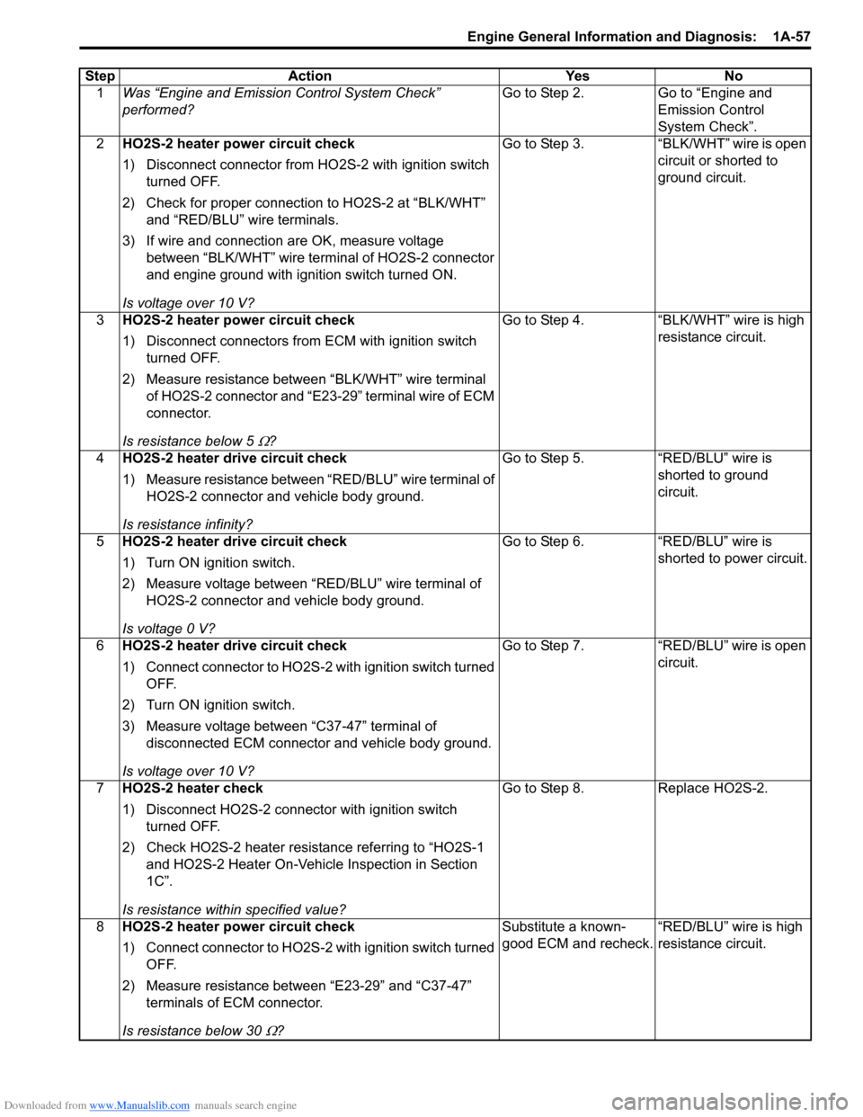
StepAction YesNo
1 Was “Engine and Emission Control System Check”
performed? Go to Step 2.
Go to “Engine and
Emission Control
System Check”.
2 HO2S-2 heater power circuit check
1) Disconnect connector from HO 2S-2 with ignition switch
turned OFF.
2) Check for proper connection to HO2S-2 at “BLK/WHT” and “RED/BLU” wire terminals.
3) If wire and connection are OK, measure voltage between “BLK/WHT” wire terminal of HO2S-2 connector
and engine ground with ignition switch turned ON.
Is voltage over 10 V? Go to Step 3.
“BLK/WHT” wire is open
circuit or shorted to
ground circuit.
3 HO2S-2 heater power circuit check
1) Disconnect connectors from ECM with ignition switch
turned OFF.
2) Measure resistance between “BLK/WHT” wire terminal of HO2S-2 connector and “E23-29” terminal wire of ECM
connector.
Is resistance below 5
Ω? Go to Step 4. “BLK/WHT” wire is high
resistance circuit.
4 HO2S-2 heater drive circuit check
1) Measure resistance between “RED/BLU” wire terminal of
HO2S-2 connector and vehicle body ground.
Is resistance infinity? Go to Step 5. “RED/BLU” wire is
shorted to ground
circuit.
5 HO2S-2 heater drive circuit check
1) Turn ON ignition switch.
2) Measure voltage between “RED/BLU” wire terminal of
HO2S-2 connector and vehicle body ground.
Is voltage 0 V? Go to Step 6. “RED/BLU” wire is
shorted to power circuit.
6 HO2S-2 heater drive circuit check
1) Connect connector to HO2S-2 with ignition switch turned
OFF.
2) Turn ON ignition switch.
3) Measure voltage between “C37-47” terminal of disconnected ECM connector and vehicle body ground.
Is voltage over 10 V? Go to Step 7.
“RED/BLU” wire is open
circuit.
7 HO2S-2 heater check
1) Disconnect HO2S-2 connector with ignition switch
turned OFF.
2) Check HO2S-2 heater resistance referring to “HO2S-1 and HO2S-2 Heater On-Vehicle Inspection in Section
1C”.
Is resistance within specified value? Go to Step 8.
Replace HO2S-2.
8 HO2S-2 heater power circuit check
1) Connect connector to HO2S-2 with ignition switch turned
OFF.
2) Measure resistance between “E23-29” and “C37-47” terminals of ECM connector.
Is resistance below 30
Ω? Substitute a known-
good ECM and recheck.
“RED/BLU” wire is high
resistance circuit.
Page 109 of 1496
Downloaded from www.Manualslib.com manuals search engine Engine General Information and Diagnosis: 1A-59
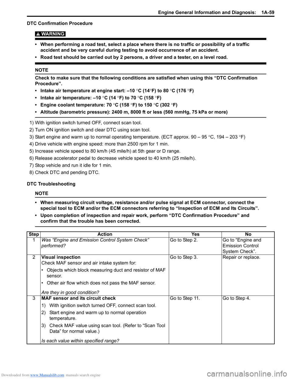
DTC Confirmation Procedure
WARNING!
• When performing a road test, select a place where there is no traffic or possibility of a traffic accident and be very careful during testing to avoid occurrence of an accident.
• Road test should be carried out by 2 persons, a driver and a tester, on a level road.
NOTE
Check to make sure that the following conditions are satisfied when using this “DTC Confirmation
Procedure”.
• Intake air temperature at engine start: –10 °C (14 °F) to 80 °C (176 °F)
• Intake air temperature: –10 °C (14 °F) to 70 °C (158 °F)
• Engine coolant temperature: 70 °C (158 °F) to 150 °C (302 °F)
• Altitude (barometric pressure): 2400 m, 8000 ft or less (560 mmHg, 75 kPa or more)
1) With ignition switch turned OFF, connect scan tool.
2) Turn ON ignition switch and clear DTC using scan tool.
3) Start engine and warm up to normal operating temperature. (ECT approx. 90 – 95 °C, 194 – 203 °F)
4) Drive vehicle with engine speed: more than 2500 rpm for 1 min.
5) Increase vehicle speed to 80 km/h (45 mile/h) at 5th gear or D range.
6) Release accelerator pedal to decrease vehicle speed to 40 km/h (25 mile/h).
7) Stop vehicle and run it idle for 1 min.
8) Check DTC and pending DTC.
DTC Troubleshooting
NOTE
• When measuring circuit voltage, resistance and/ or pulse signal at ECM connector, connect the
special tool to ECM and/or the ECM connectors re ferring to “Inspection of ECM and Its Circuits”.
• Upon completion of inspection and repair work, perform “DTC Confirmation Procedure” and confirm that the trouble has been corrected.
Step Action YesNo
1 Was “Engine and Emission Control System Check”
performed? Go to Step 2.
Go to “Engine and
Emission Control
System Check”.
2 Visual inspection
Check MAF sensor and air intake system for:
• Objects which block measuring duct and resistor of MAF
sensor.
• Other air flow which does not pass the MAF sensor.
Are they in good condition? Go to Step 3.
Repair or replace.
3 MAF sensor and its circuit check
1) With ignition switch turned OFF, connect scan tool.
2) Start engine and warm up to normal operation
temperature.
3) Check MAF value using scan tool. (Refer to “Scan Tool Data” for normal value.)
Is each value within specified range? Go to Step 11. Go to Step 4.
Page 127 of 1496
Downloaded from www.Manualslib.com manuals search engine Engine General Information and Diagnosis: 1A-77
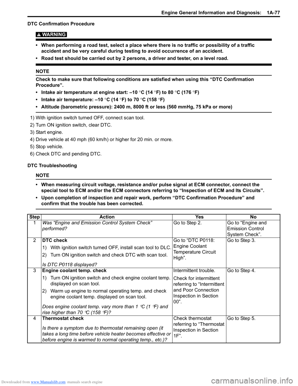
DTC Confirmation Procedure
WARNING!
• When performing a road test, select a place where there is no traffic or possibility of a traffic accident and be very careful during testing to avoid occurrence of an accident.
• Road test should be carried out by 2 persons, a driver and tester, on a level road.
NOTE
Check to make sure that following conditions ar e satisfied when using this “DTC Confirmation
Procedure”.
• Intake air temperature at engine start: –10 °C (14 ° F) to 80 °C (176 °F)
• Intake air temperature: –10 °C (14 °F) to 70 °C (158 °F)
• Altitude (barometric pressure): 2400 m, 8000 ft or less (560 mmHg, 75 kPa or more)
1) With ignition switch turned OFF, connect scan tool.
2) Turn ON ignition switch, clear DTC.
3) Start engine.
4) Drive vehicle at 40 mph (60 km/h) or higher for 20 min. or more.
5) Stop vehicle.
6) Check DTC and pending DTC.
DTC Troubleshooting
NOTE
• When measuring circuit voltage, resistance and/ or pulse signal at ECM connector, connect the
special tool to ECM and/or the ECM connectors re ferring to “Inspection of ECM and Its Circuits”.
• Upon completion of inspection and repair work, perform “DTC Confirmation Procedure” and confirm that the trouble has been corrected.
Step Action YesNo
1 Was “Engine and Emission Control System Check”
performed? Go to Step 2.
Go to “Engine and
Emission Control
System Check”.
2 DTC check
1) With ignition switch turned OFF, install scan tool to DLC.
2) Turn ON ignition switch and check DTC with scan tool.
Is DTC P0118 displayed? Go to “DTC P0118:
Engine Coolant
Temperature Circuit
High”.
Go to Step 3.
3 Engine coolant temp. check
1) Turn ON ignition switch and check engine coolant temp.
displayed on scan tool.
2) Warm up engine to normal operating temp. and check engine coolant temp. displayed on scan tool.
Does engine coolant te mp. vary more than 1
°C (1 °F) and
rise higher than 70
°C (158 °F)? Intermittent trouble.
Check for intermittent
referring to “Intermittent
and Poor Connection
Inspection in Section
00”.
Go to Step 4.
4 Thermostat check
Is there a symptom due to thermostat remaining open (it
takes a long time before vehicle heater becomes effective or
before engine is warmed to normal operating temp., etc.)? Check thermostat
referring to “Thermostat
Inspection in Section
1F”.
Go to Step 5.
Page 139 of 1496

Downloaded from www.Manualslib.com manuals search engine Engine General Information and Diagnosis: 1A-89
DTC Confirmation Procedure
WARNING!
• When performing a road test, select a place where there is no traffic or possibility of a traffic accident and be very careful during testing to avoid occurrence of an accident.
• Road test should be carried out by 2 persons, a driver and a tester, on a level road.
NOTE
Check to make sure that following conditions ar e satisfied when using this “DTC Confirmation
Procedure”.
• Intake air temperature at engine start: –10 °C (14 ° F) to 80 °C (176 °F)
• Intake air temperature: –10 °C (14 °F) to 70 °C (158 °F)
• Engine coolant temperature: 70 °C (158 °F) to 150 °C (302 °F)
• Altitude (barometric pressure): 2400 m, 8000 ft or less (560 mmHg, 75 kPa or more)
1) With ignition switch turned OFF, connect scan tool.
2) Turn ON ignition switch and clear DTC using scan tool.
3) Start engine and warm up to normal operating temperature.
4) Drive vehicle at 40 mph (60 km/h) or higher. (engine speed: 2500 – 3000 r/min.)
5) Keep above vehicle speed for 6 min. or more. (Throt tle valve opening is kept constant in this step.)
6) Release accelerator pedal and with engine brake applied, keep vehicle coasting (with fuel cut for 3 sec. or more)
and then stop vehicle.
7) Check DTC and pending DTC.
DTC Troubleshooting
NOTE
• When measuring circuit voltage, resistance and/ or pulse signal at ECM connector, connect the
special tool to ECM and/or the ECM connectors re ferring to “Inspection of ECM and Its Circuits”.
• Upon completion of inspection and repair work, perform “DTC Confirmation Procedure” and confirm that the trouble has been corrected.
Step Action YesNo
1 Was “Engine and Emission Control System Check”
performed? Go to Step 2.
Go to “Engine and
Emission Control
System Check”.
2 Is there DTC(s) other than HO2S-1? Go to applicable DTC
diag. flow.Go to Step 3.
3 HO2S-1 signal check
1) Connect scan tool to DLC with ignition switch turned
OFF.
2) Warm up engine to normal operating temperature and keep it at 2000 r/min. for 60 sec.
3) Repeat racing engine (Repeat depressing accelerator pedal 5 to 6 times continuous ly to enrich A/F mixture and
take foot off from pedal to enlean it).
Does HO2S-1 output voltage deflect between below 0.3 V
and over 0.6 V repeatedly? Intermittent trouble.
Check for intermittent
referring to “Intermittent
and Poor Connection
Inspection in Section
00”. If check result is
OK, go to Step 9.
Go to Step 4.