2007 SUZUKI SWIFT Head bolts
[x] Cancel search: Head boltsPage 384 of 1496

Downloaded from www.Manualslib.com manuals search engine 1G-9 Fuel System:
Installation
Reverse removal procedure for installation noting the
following.
• Replace injector O-ring (1) with new one using care not to damage it.
• Check if cushion (2) is scor ed or damaged. If it is,
replace with new one.
• Apply thin coat of fuel to O-rings (1) and then install injectors (3) into delivery pipe (4) and cylinder head.
Make sure that injectors rota te smoothly (6). If not,
probable cause is incorrect installation of O-ring.
Replace O-ring with new one.
• Tighten delivery pipe bolts (5) to specified torque and make sure that inject ors rotate smoothly.
Tightening torque
Fuel delivery pipe bolt (a): 25 N·m (2.5 kgf-m, 18.0
lb-ft)
• After installation, with engine OFF and ignition switch ON, check for fuel leaks around fuel line connection.Fuel Injector InspectionS7RS0B1706009
WARNING!
Before starting the following procedure, be
sure to observe “Precautions on Fuel System
Service” in order to reduce the risk or fire
and personal injury.
1) Relieve fuel pressure according to “Fuel Pressure Relief Procedure” if equipped.
2) Disconnect fuel feed hose from delivery pipe.
3) Set special tools as follows.
Special tool
(A): 09912–58421
(B): 09930–88530
(C): 09912–57610
a) Fit washer (1) (inside diameter 13.5 – 14.5 mm (0.532 – 0.570 in.)) to injector (2), and then
install injector to special tool (A).
b) Connect special tool (B) to injector.
c) Install special tool (C) to special tool (A).
d) Connect fuel feed hose to special tool (A).
I3RM0A170011-01
(B)
(A)
(A) (C)
2
1
I6RW0B170014-01
Page 400 of 1496

Downloaded from www.Manualslib.com manuals search engine 1H-8 Ignition System:
Ignition Coil Assembly (Including ignitor)
Removal and Installation
S7RS0B1806005
Removal1) Disconnect negative (–) cable at battery.
2) Remove air cleaner assembly with air intake pipe and cylinder head upper cover.
3) Disconnect ignition coil coupler.
4) Disconnect high-tension cord (3) from ignition coil assembly (2).
5) Remove ignition coil bolts (1) and then pull out ignition coil assembly.
Installation 1) Install ignition coil assembly (2).
2) Tighten ignition coil bolts (1) to specified torque, and then connect igni tion coil coupler.
Tightening torque
Ignition coil bolt (a): 10 N·m (1.0 kgf-m, 7.5 lb-ft)
3) Install high-tension cord (3) to ignition coil assembly while gripping its cap.
4) Install cylinder head upper cover and air cleaner assembly with air intake pipe.
5) Connect negative (–) cable to battery.
Ignition Coil Assembly (Including ignitor)
Inspection
S7RS0B1806006
Measure secondary coil for resistance.
If resistance is out of specification, replace ignition coil
assembly.
Secondary coil resistance
7.5 – 10.3 k Ω at 20 °C, 68 ° F
Ignition Timing InspectionS7RS0B1806007
NOTE
• Ignition timing is not adjustable. If ignition
timing is out of specification, check
system related parts.
• Before starting engine, place transmission gear shift lever in “Neutral” (shift selector
lever to “P” range for A/T model), and set
parking brake.
1) Connect scan tool to DLC (1) with ignition switch OFF.
Special tool
(A): SUZUKI scan tool
2) Start engine and warm it up to normal operating temperature.
3) Make sure that all of electrical loads except ignition are switched off.
4) Check to be sure that idle speed is within specification referring to “Idle Speed and IAC
Throttle Valve Opening Inspection in Section 1A”
5) Fix ignition timing by using “Fixed Spark” of “Misc Test” mode on scan tool.
I2RH0B180006-01
I3RM0A180004-01
I2RH0B180007-01
(A)
1
I4RS0B180003-01
Page 426 of 1496

Downloaded from www.Manualslib.com manuals search engine 1K-3 Exhaust System:
Exhaust Manifold Removal and InstallationS7RS0B1B06002
Removal
WARNING!
To avoid danger of being burned, do not
service exhaust system while it is still hot.
Service should be performed after system
cools down.
1) Disconnect negative cable at battery.
2) Remove engine cover.
3) Remove front bumper with front grille referring to
“Front Bumper and Rear Bumper Components in
Section 9K”.
4) Remove radiator referring to “Radiator Removal and Installation in Section 1F ” for equipped with A/C.
5) With hose connected, detach A/C condenser from vehicle body for equipped with A/C.
6) Remove exhaust manifold cover from exhaust manifold.
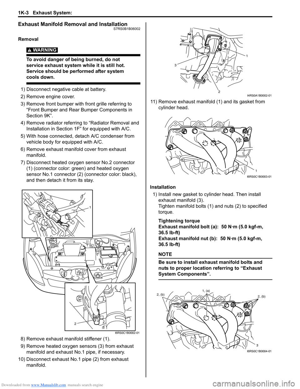
7) Disconnect heated oxygen sensor No.2 connector (1) (connector color: green) and heated oxygen
sensor No.1 connector (2) (connector color: black),
and then detach it from its stay.
8) Remove exhaust manifold stiffener (1).
9) Remove heated oxygen sensors (3) from exhaust manifold and exhaust No.1 pipe, if necessary.
10) Disconnect exhaust No.1 pipe (2) from exhaust manifold. 11) Remove exhaust manifold (1) and its gasket from
cylinder head.
Installation 1) Install new gasket to cylinder head. Then install exhaust manifold (3).
Tighten manifold bolts (1) and nuts (2) to specified
torque.
Tightening torque
Exhaust manifold bolt (a): 50 N·m (5.0 kgf-m,
36.5 lb-ft)
Exhaust manifold nut (b): 50 N·m (5.0 kgf-m,
36.5 lb-ft)
NOTE
Be sure to install exhaust manifold bolts and
nuts to proper location referring to “Exhaust
System Components”.
1
2
I6RS0C1B0002-01
1
2
3
I4RS0A1B0002-01
1
I6RS0C1B0003-01
2, (b) 2, (b)
3
1, (a)
I6RS0C1B0004-01
Page 452 of 1496

Downloaded from www.Manualslib.com manuals search engine 2B-19 Front Suspension:
13) Install suspension control arm referring to
“Suspension Control Arm / Bushing Removal and
Installation”.
14) Connect couplers of torque sensor and P/S motor.
15) Connect tie-rod ends to knuckles (right & left) and then install cotter pins referring to “Tie-Rod End
Removal and Installa tion in Section 6C”.
16) Be sure that steering wheel and brake discs (right & left) are all straight-ahead position and then insert
steering lower shaft (5) into steering pinion shaft (3)
with matching marks (4).
17) Tighten steering shaft joint lower bolt (1) and upper bolt (2) to specified torque (Lower side first and then
upper side).
Tightening torque
Steering shaft joint bolt (a): 25 N·m (2.5 kgf-m,
18.5 lb-ft)
18) Install both wheels and tighten wheel bolts to specified torque.
Tightening torque
Wheel bolt: 85 N·m (8.5 kgf-m, 61.5 lb-ft)
19) Lower hoist.
20) Check toe setting. Adjust as required refer to “Front Wheel Alignment Inspection and Adjustment”.
Front Suspension Frame CheckS7RS0B2206016
Inspect for cracks, deformation or damage.
If defective, replace.
Front Stabilizer Bar, Bushing and/or Joint
Check
S7RS0B2206017
Stabilizer Bar
Inspect for damage or deformation.
If defective, replace.
Stabilizer Bushing
Inspect for damage, wear or deterioration.
If defective, replace.
Stabilizer Joint
1) Check for smooth rotation.
2) Check damages of ball stud.
3) Check damages of dust cover.
NOTE
Stabilizer joint (1) cannot be disassembled.
If there is any damage to either parts, stabilizer joint
assembly must be replaced as a complete unit.
Front Suspension Fasteners CheckS7RS0B2206018
Check each bolt and nut fastening suspension parts for
tightness. Tighten loose one, if any, to specified torque,
referring to “Front Suspension Construction”.
5
4
1, (a)
3
2, (a)
1, (a)
5
I4RS0B630016-01
I4RS0A220054-01
I4RS0A220052-01
I4RS0A220056-01
1
I4RH01220007-01
Page 750 of 1496

Downloaded from www.Manualslib.com manuals search engine 5A-106 Automatic Transmission/Transaxle:
Automatic Transaxle Unit Dismounting and
Remounting
S7RS0B5106031
Dismounting1) Take down transaxle with engine. For its procedure, refer to “Engine Assembly Removal and Installation
in Section 1D”.
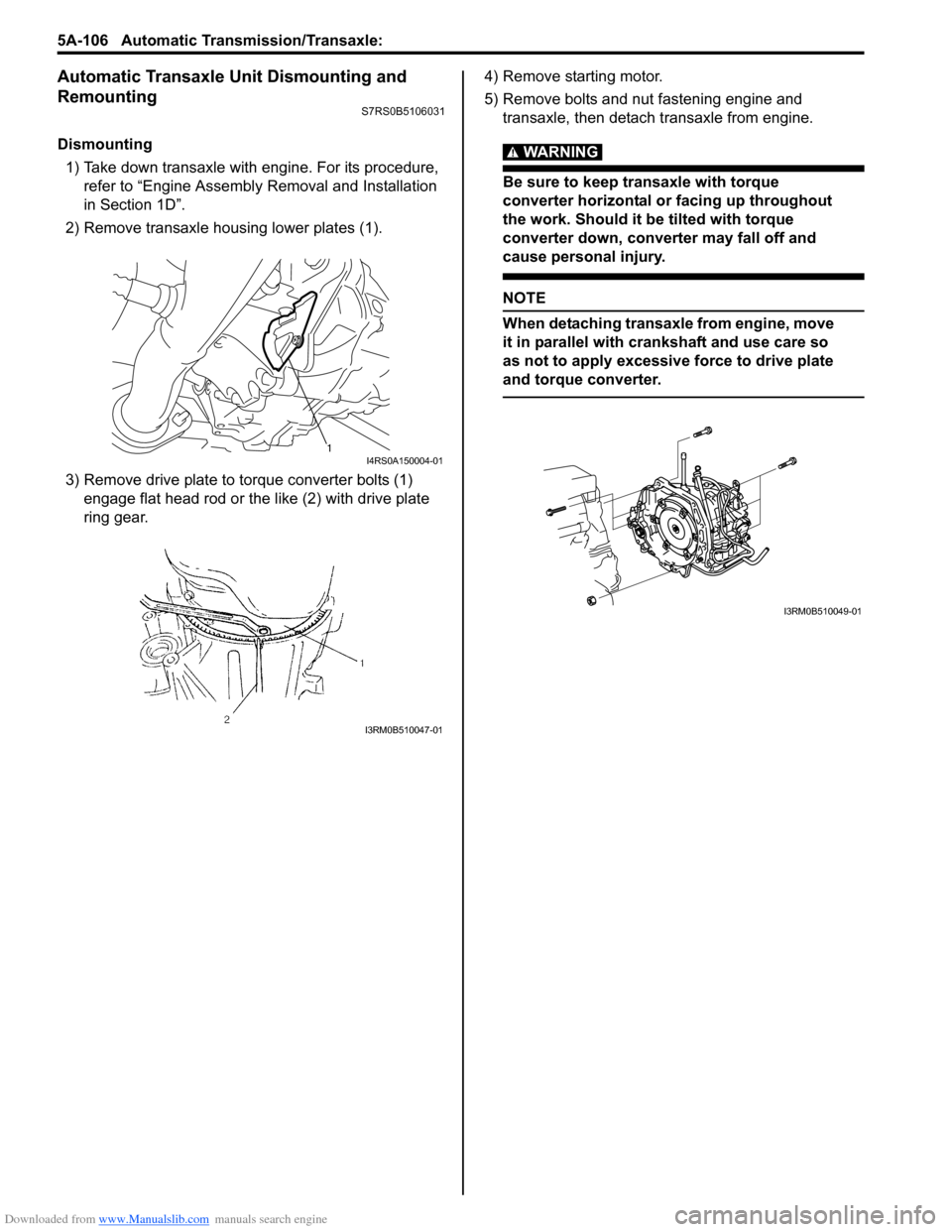
2) Remove transaxle housing lower plates (1).
3) Remove drive plate to torque converter bolts (1) engage flat head rod or the like (2) with drive plate
ring gear. 4) Remove starting motor.
5) Remove bolts and nut fastening engine and
transaxle, then detach transaxle from engine.WARNING!
Be sure to keep transaxle with torque
converter horizontal or facing up throughout
the work. Should it be tilted with torque
converter down, converter may fall off and
cause personal injury.
NOTE
When detaching transaxle from engine, move
it in parallel with cranks haft and use care so
as not to apply excessive force to drive plate
and torque converter.
1I4RS0A150004-01
I3RM0B510047-01
I3RM0B510049-01
Page 751 of 1496

Downloaded from www.Manualslib.com manuals search engine Automatic Transmission/Transaxle: 5A-107
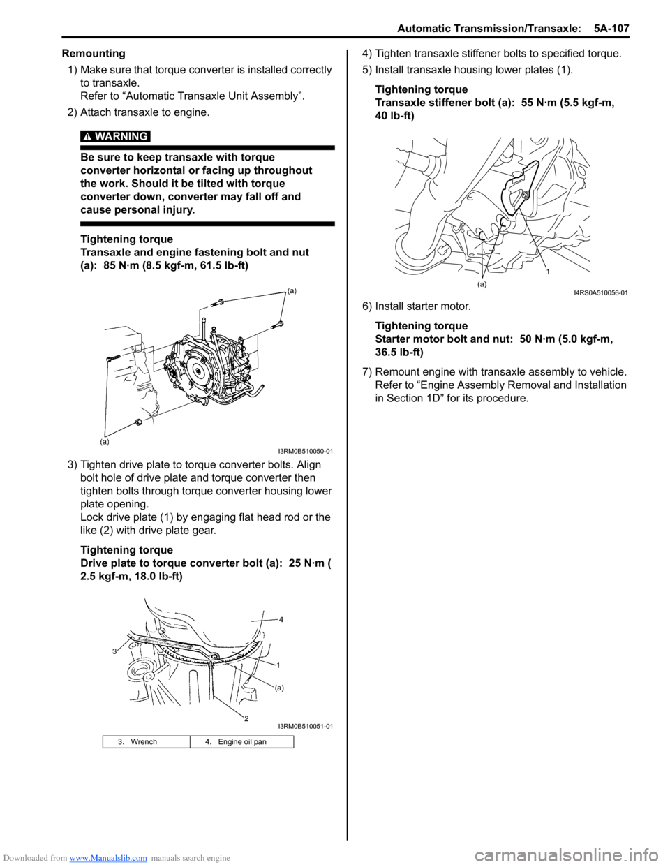
Remounting1) Make sure that torque converter is installed correctly to transaxle.
Refer to “Automatic Transaxle Unit Assembly”.
2) Attach transaxle to engine.
WARNING!
Be sure to keep transaxle with torque
converter horizontal or facing up throughout
the work. Should it be tilted with torque
converter down, converter may fall off and
cause personal injury.
Tightening torque
Transaxle and engine fastening bolt and nut
(a): 85 N·m (8.5 kgf-m, 61.5 lb-ft)
3) Tighten drive plate to torque converter bolts. Align bolt hole of drive plate and torque converter then
tighten bolts through torque converter housing lower
plate opening.
Lock drive plate (1) by engaging flat head rod or the
like (2) with drive plate gear.
Tightening torque
Drive plate to torque converter bolt (a): 25 N·m (
2.5 kgf-m, 18.0 lb-ft) 4) Tighten transaxle stiffener bolts to specified torque.
5) Install transaxle housing lower plates (1).
Tightening torque
Transaxle stiffener bolt (a): 55 N·m (5.5 kgf-m,
40 lb-ft)
6) Install starter motor. Tightening torque
Starter motor bolt and nut: 50 N·m (5.0 kgf-m,
36.5 lb-ft)
7) Remount engine with transaxle assembly to vehicle. Refer to “Engine Assembly Removal and Installation
in Section 1D” for its procedure.
3. Wrench 4. Engine oil pan
I3RM0B510050-01
I3RM0B510051-01
1
(a)
I4RS0A510056-01
Page 862 of 1496

Downloaded from www.Manualslib.com manuals search engine 5C-10 Clutch:
3) Aligning clutch disc to flywheel center using special
tool, install clutch cover (1) and bolts (2). Then
tighten bolts (2) to specification.
NOTE
• While tightening clutch cover bolts, compress clutch disc with special tool
(clutch center guide) by hand so that disc
is centered.
• Tighten cover bolts little by little evenly in diagonal order.
Special tool
(A): 09924–17811
(B): 09923–36320
Tightening torque
Clutch cover bolt (a): 23 N·m (2.3 kgf-m, 17.0 lb-
ft)
4) Slightly apply grease to input shaft (1), then join manual transaxle assembly with engine referring to
“Manual Transaxle Unit Dismounting and
Remounting in Section 5B”.
“A”: Grease 99000–25210 (SUZUKI Super
Grease I)
NOTE
When inserting transaxle input shaft to clutch
disc, turn crankshaft li ttle by little to match
the splines.
Clutch Cover, Clutch Disc and Flywheel
Inspection
S7RS0B5306015
Input Shaft Bearing
Check bearing (1) for smooth ro tation and replace it if
abnormality is found.
Clutch Disc
Measure depth of rivet head depression, i.e. distance
between rivet head and facing surface.
If depression is found to hav e reached service limit at
any of rivet holes (2), repl ace clutch disc assembly (1).
Rivet head depth
Standard: 1.65 – 2.25 mm (0.06 – 0.09 in.)
Limit: 0.5 mm (0.02 in.)
I4RS0A530017-01
I4RS0A530018-01
I3RM0A530014-01
I4RS0A530019-01
Page 881 of 1496

Downloaded from www.Manualslib.com manuals search engine Steering Wheel and Column: 6B-10
5) Tighten new bolts (1) until head of each bolt is broken off.
6) Turn ignition key to “ACC” or “ON” position and check to be sure that st eering shaft (2) rotates
smoothly. Also check for lock operation.
7) Install steering column. Re fer to “Steering Column
Removal and Installation”.
8) If steering lock assembly has replaced, after completing installation, register ignition key
transponder code in ECM referring to “Registration
of the Ignition Key in Section 10C”.
Steering Lower Shaft Removal and InstallationS7RS0B6206010
CAUTION!
Never turn steering wheel while steering
lower shaft is removed.
Should it have been turned and contact coil
have got out of its centered position, it needs
to be centered again. Also, turning steering
wheel more than about two and a half turns
will break contact coil.
Removal
1) Turn steering wheel so that vehicle’s front tires are at straight-ahead position.
2) Turn ignition switch to LOCK position and remove key.
3) Remove steering joint cover.
4) Make alignment marks (4) on lower shaft (1) and shaft joint of steering colu mn (2) and lower shaft (1)
and pinion shaft (3) for a guide during reinstallation.
5) Remove lower shaf t joint bolts (5).
6) Remove steering lower shaft (1). Installation
1) Be sure that front wheels are in straight forward state.
2) Align flat part “A” of steering lower shaft (1) with bolt hole “B” of shaft joint (2) of column as shown. Then
insert lower shaft into shaf t joint of steering column
with matching marks (4).
3) Insert lower shaft (1) into pinion shaft (3) with matching marks (4).
4) Tighten joint bolt (pinion shaft side) (6) to specified
torque first and then joint bolt (steering column side)
(5) to specified torque.
Tightening torque
Steering shaft joint bolt (a ): 25 N·m (2.5 kgf-m,
18.5 lb-ft)
I4RS0B620007-02
I4RS0A620020-01
I6RS0C620002-01