2007 SUZUKI SWIFT ECT sensor location
[x] Cancel search: ECT sensor locationPage 45 of 1496
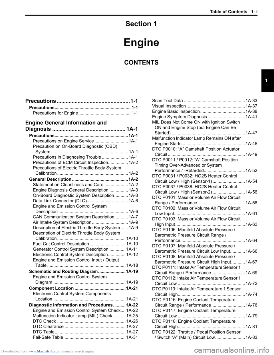
Downloaded from www.Manualslib.com manuals search engine Table of Contents 1- i
1
Section 1
CONTENTS
Engine
Precautions ................................................. 1-1
Precautions............................................................. 1-1
Precautions for Engine .......................................... 1-1
Engine General Information and
Diagnosis ............. .................................... 1A-1
Precautions........................................................... 1A-1
Precautions on Engine Service ........................... 1A-1
Precaution on On-Board Diagnostic (OBD) System .............................................................. 1A-1
Precautions in Diagnosing Trouble ..................... 1A-1
Precautions of ECM Circuit Inspection................ 1A-2
Precautions of Electric Throttle Body System
Calibration ......................................................... 1A-2
General Description ............................................. 1A-2 Statement on Cleanliness and Care ................... 1A-2
Engine Diagnosis General Description ............... 1A-3
On-Board Diagnostic System Description ........... 1A-3
Data Link Connector (DLC) ................................. 1A-6
Engine and Emission Control System Description ........................................................ 1A-6
CAN Communication System Description........... 1A-7
Air Intake System Description ............................. 1A-9
Description of Electric Throttle Body System ...... 1A-9
Description of Electric Throttle Body System Calibration ....................................................... 1A-10
Fuel Cut Control Description ............................. 1A-10
Generator Control System Description ............. 1A-11
Electronic Control System Description .............. 1A-12
Engine and Emission Control Input / Output Table ............................................................... 1A-18
Schematic and Routing Diagram ...................... 1A-19 Engine and Emission Control System Diagram .......................................................... 1A-19
Component Locatio n ......................................... 1A-21
Electronic Control System Components Location .......................................................... 1A-21
Diagnostic Information and Procedures .......... 1A-22 Engine and Emission Control System Check.... 1A-22
Malfunction Indicator Lamp (MIL) Check .......... 1A-25
DTC Check ....................................................... 1A-26
DTC Clearance ................................................. 1A-27
DTC Table ......................................................... 1A-27
Fail-Safe Table ................ .................................. 1A-31 Scan Tool Data ................................................. 1A-33
Visual Inspection ............................................... 1A-37
Engine Basic Inspection .................................... 1A-38
Engine Symptom Diagnosis .............................. 1A-41
MIL Does Not Come ON with Ignition Switch
ON and Engine Stop (but Engine Can Be
Started) ........................................................... 1A-47
Malfunction Indicator Lamp Remains ON after Engine Starts................................................... 1A-48
DTC P0010: “A” Camshaft Position Actuator Circuit .............................................................. 1A-49
DTC P0011 / P0012: “A” Camshaft Position - Timing Over-Advanced or System
Performance / -Retarded................................. 1A-52
DTC P0031 / P0032: HO2S Heater Control Circuit Low / High (Sensor-1) .......................... 1A-54
DTC P0037 / P0038: HO2S Heater Control Circuit Low / High (Sensor-2) .......................... 1A-56
DTC P0101: Mass or Volume Air Flow Circuit Range / Performance ...................................... 1A-58
DTC P0102: Mass or Volume Air Flow Circuit Low Input......................................................... 1A-61
DTC P0103: Mass or Volume Air Flow Circuit High Input ........................................................ 1A-63
DTC P0106: Manifold Absolute Pressure /
Barometric Pressure Circuit Range /
Performance.................................................... 1A-64
DTC P0107: Manifold Absolute Pressure /
Barometric Pressure Circ uit Low Input............ 1A-66
DTC P0108: Manifold Absolute Pressure /
Barometric Pressure Circ uit High Input ........... 1A-67
DTC P0111: Intake Air Temperature Sensor 1 Circuit Range / Performance ........................... 1A-69
DTC P0112: Intake Air Temperature Sensor 1 Circuit Low ...................................................... 1A-72
DTC P0113: Intake Air Temperature 1 Sensor Circuit High...................................................... 1A-74
DTC P0116: Engine Coolant Temperature Circuit Range / Performance ........................... 1A-76
DTC P0117: Engine Coolant Temperature Circuit Low ...................................................... 1A-79
DTC P0118: Engine Coolant Temperature Circuit High...................................................... 1A-81
DTC P0122: Throttle / Pedal Position Sensor / Switch “A” (Main) Circuit Low ........................ 1A-83
Page 48 of 1496

Downloaded from www.Manualslib.com manuals search engine 1-iv Table of Contents
Engine Lubrication System.....................1E-1
General Description ............................................. 1E-1
Engine Lubrication Description ........................... 1E-1
Diagnostic Information and Procedures ............ 1E-2 Oil Pressure Check ............................................. 1E-2
Repair Instructions ........... ................................... 1E-3
Heat Exchanger Components ............................. 1E-3
Heat Exchanger On-Vehicle Inspection .............. 1E-4
Heat Exchanger Removal and Installation .......... 1E-4
Oil Pan and Oil Pump Strainer Components....... 1E-5
Oil Pan and Oil Pump Strainer Removal and
Installation ......................................................... 1E-5
Oil Pan and Oil Pump Stra iner Cleaning ............. 1E-7
Oil Pump Components ........................................ 1E-8
Oil Pump Removal and Installation ..................... 1E-8
Oil Pump Disassembly and Reassembly ............ 1E-8
Oil Pump Inspection ............................................ 1E-9
Specifications .... ................................................. 1E-11
Tightening Torque Specifications ...................... 1E-11
Special Tools and Equipmen t ........................... 1E-11
Recommended Service Material ....................... 1E-11
Special Tool ...................................................... 1E-11
Engine Cooling System ..... ...................... 1F-1
General Description .......... ................................... 1F-1
Cooling System Descriptio n ................................ 1F-1
Coolant Description ............................................. 1F-1
Schematic and Routing Diagram ........................ 1F-2 Coolant Circulation .............................................. 1F-2
Diagnostic Information and Procedures ............ 1F-4 Engine Cooling Symptom Diagnosis ................... 1F-4
Repair Instructions ........... ................................... 1F-5
Cooling System Components.............................. 1F-5
Coolant Level Check ........................................... 1F-6
Engine Cooling System Inspection and Cleaning ............................................................ 1F-6
Cooling System Draining.. ................................... 1F-6
Cooling System Flush and Refill ......................... 1F-7
Cooling Water Pipes or Hoses Removal and Installation ......................................................... 1F-7
Thermostat Removal and In stallation.................. 1F-8
Thermostat Inspection......................................... 1F-8
Radiator Cooling Fan Motor On-Vehicle Inspection .......................................................... 1F-9
Radiator Cooling Fan Rela y Inspection............... 1F-9
Radiator Cooling Fan Removal and Installation ....................................................... 1F-10
Radiator On-Vehicle Inspection and Cleaning .. 1F-10
Radiator Removal and Inst allation .................... 1F-10
Water Pump Removal and In stallation .............. 1F-11
Water Pump Inspection ..................................... 1F-11
Specifications .... ................................................. 1F-12
Tightening Torque Specifications ...................... 1F-12
Special Tools and Equipmen t ........................... 1F-12
Recommended Service Material ....................... 1F-12
Fuel System ................... .......................... 1G-1
Precautions.......................................................... 1G-1 Precautions on Fuel System Service ................. 1G-1
General Description ............................................ 1G-1 Fuel System Description .................................... 1G-1
Fuel Delivery System Description ...................... 1G-1
Fuel Pump Description ....................................... 1G-2
Schematic and Routing Diagram ....................... 1G-2 Fuel Delivery System Diag ram........................... 1G-2
Diagnostic Information and Procedures ........... 1G-2 Fuel Pressure Inspection ................................... 1G-2
Fuel Cut Operation Inspection ........................... 1G-3
Repair Instructions ............ ................................. 1G-4
Fuel System Components .................................. 1G-4
Fuel Hose Disconnecting and Reconnecting ..... 1G-5
Fuel Pressure Relief Procedure ......................... 1G-7
Fuel Leakage Check Procedure......................... 1G-7
Fuel Lines On-Vehicle Inspection ...................... 1G-7
Fuel Pipe Removal and Installation.................... 1G-7
Fuel Injector On-Vehicle Inspection ................... 1G-8
Fuel Injector Removal and Installation ............... 1G-8
Fuel Injector Inspection ...................................... 1G-9
Fuel Filler Cap Inspection . ............................... 1G-10
Fuel Tank Inlet Valve Removal and Installation ...................................................... 1G-11
Fuel Tank Inlet Valve Inspection ...................... 1G-12
Fuel Tank Removal and Installation ................. 1G-12
Fuel Tank Inspection ........................................ 1G-13
Fuel Tank Purging Procedure .......................... 1G-14
Fuel Pump On-Vehicle Inspection.................... 1G-14
Fuel Pump Assembly Removal and Installation ...................................................... 1G-14
Main Fuel Level Sensor Removal and Installation ...................................................... 1G-15
Fuel Pump Inspection ...................................... 1G-16
Specifications ..................... ............................... 1G-16
Tightening Torque Specifications ..................... 1G-16
Special Tools and Equipmen t .......................... 1G-17
Special Tool ..................................................... 1G-17
Ignition System .............. .......................... 1H-1
General Description .............................................1H-1
Ignition System Construction ..............................1H-1
Schematic and Routing Diagram ........................1H-2 Ignition System Wiring Circuit Diagram...............1H-2
Component Location ............ ...............................1H-3
Ignition System Components Location................1H-3
Diagnostic Information and Procedures ............1H-4 Ignition System Symptom Diagnosis...................1H-4
Reference Waveform of Ignition System.............1H-4
Ignition System Check ........................................1H-4
Ignition Spark Test ..............................................1H-6
Repair Instructions ............ ..................................1H-6
High-Tension Cord Removal and Installation......1H-6
High-Tension Cord Inspection.............................1H-7
Spark Plug Removal and Installation ..................1H-7
Spark Plug Inspection .........................................1H-7
Ignition Coil Assembly (Including ignitor)
Removal and Installation ...................................1H-8
Ignition Coil Assembly (Including ignitor)
Inspection ..........................................................1H-8
Page 52 of 1496
Downloaded from www.Manualslib.com manuals search engine 1A-2 Engine General Information and Diagnosis:
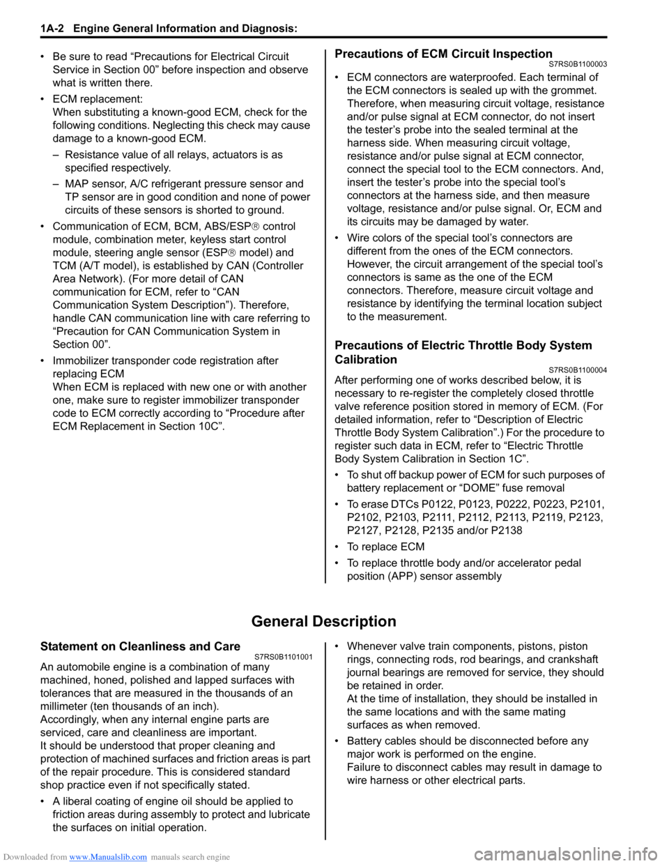
• Be sure to read “Precautions for Electrical Circuit Service in Section 00” befo re inspection and observe
what is written there.
• ECM replacement: When substituting a known-good ECM, check for the
following conditions. Neglec ting this check may cause
damage to a known-good ECM.
– Resistance value of all relays, actuators is as specified respectively.
– MAP sensor, A/C refrigerant pressure sensor and TP sensor are in good condition and none of power
circuits of these sensors is shorted to ground.
• Communication of ECM, BCM, ABS/ESP ® control
module, combination meter, keyless start control
module, steering angle sensor (ESP ® model) and
TCM (A/T model), is esta blished by CAN (Controller
Area Network). (For more detail of CAN
communication for ECM, refer to “CAN
Communication System Description”). Therefore,
handle CAN communication line with care referring to
“Precaution for CAN Communication System in
Section 00”.
• Immobilizer transponder code registration after
replacing ECM
When ECM is replaced with new one or with another
one, make sure to register immobilizer transponder
code to ECM correctly according to “Procedure after
ECM Replacement in Section 10C”.Precautions of ECM Circuit InspectionS7RS0B1100003
• ECM connectors are waterproofed. Each terminal of the ECM connectors is sealed up with the grommet.
Therefore, when measuring ci rcuit voltage, resistance
and/or pulse signal at ECM connector, do not insert
the tester’s probe into th e sealed terminal at the
harness side. When measuring circuit voltage,
resistance and/or pulse signal at ECM connector,
connect the special tool to the ECM connectors. And,
insert the tester’s probe into the special tool’s
connectors at the harness side, and then measure
voltage, resistance and/or pulse signal. Or, ECM and
its circuits may be damaged by water.
• Wire colors of the special tool’s connectors are different from the ones of the ECM connectors.
However, the circuit arrangement of the special tool’s
connectors is same as the one of the ECM
connectors. Therefore, measure circuit voltage and
resistance by identifying the terminal location subject
to the measurement.
Precautions of Electric Throttle Body System
Calibration
S7RS0B1100004
After performing one of works described below, it is
necessary to re-register the completely closed throttle
valve reference position stored in memory of ECM. (For
detailed information, refer to “Description of Electric
Throttle Body System Calibration”.) For the procedure to
register such data in ECM, refer to “Electric Throttle
Body System Calibration in Section 1C”.
• To shut off backup power of ECM for such purposes of battery replacement or “DOME” fuse removal
• To erase DTCs P0122, P01 23, P0222, P0223, P2101,
P2102, P2103, P2111, P2112, P2113, P2119, P2123,
P2127, P2128, P2135 and/or P2138
• To replace ECM
• To replace throttle body and/or accelerator pedal position (APP) sensor assembly
General Description
Statement on Cleanliness and CareS7RS0B1101001
An automobile engine is a combination of many
machined, honed, polished and lapped surfaces with
tolerances that are measured in the thousands of an
millimeter (ten thous ands of an inch).
Accordingly, when any internal engine parts are
serviced, care and cleanliness are important.
It should be understood that proper cleaning and
protection of machined surfaces and friction areas is part
of the repair procedure. This is considered standard
shop practice even if not specifically stated.
• A liberal coating of engine oil should be applied to friction areas during assembly to protect and lubricate
the surfaces on initial operation. • Whenever valve train components, pistons, piston
rings, connecting rods, rod bearings, and crankshaft
journal bearings are removed for service, they should
be retained in order.
At the time of installation, they should be installed in
the same locations and with the same mating
surfaces as when removed.
• Battery cables should be disconnected before any major work is performed on the engine.
Failure to disconnect cables may result in damage to
wire harness or other electrical parts.
Page 71 of 1496
Downloaded from www.Manualslib.com manuals search engine Engine General Information and Diagnosis: 1A-21
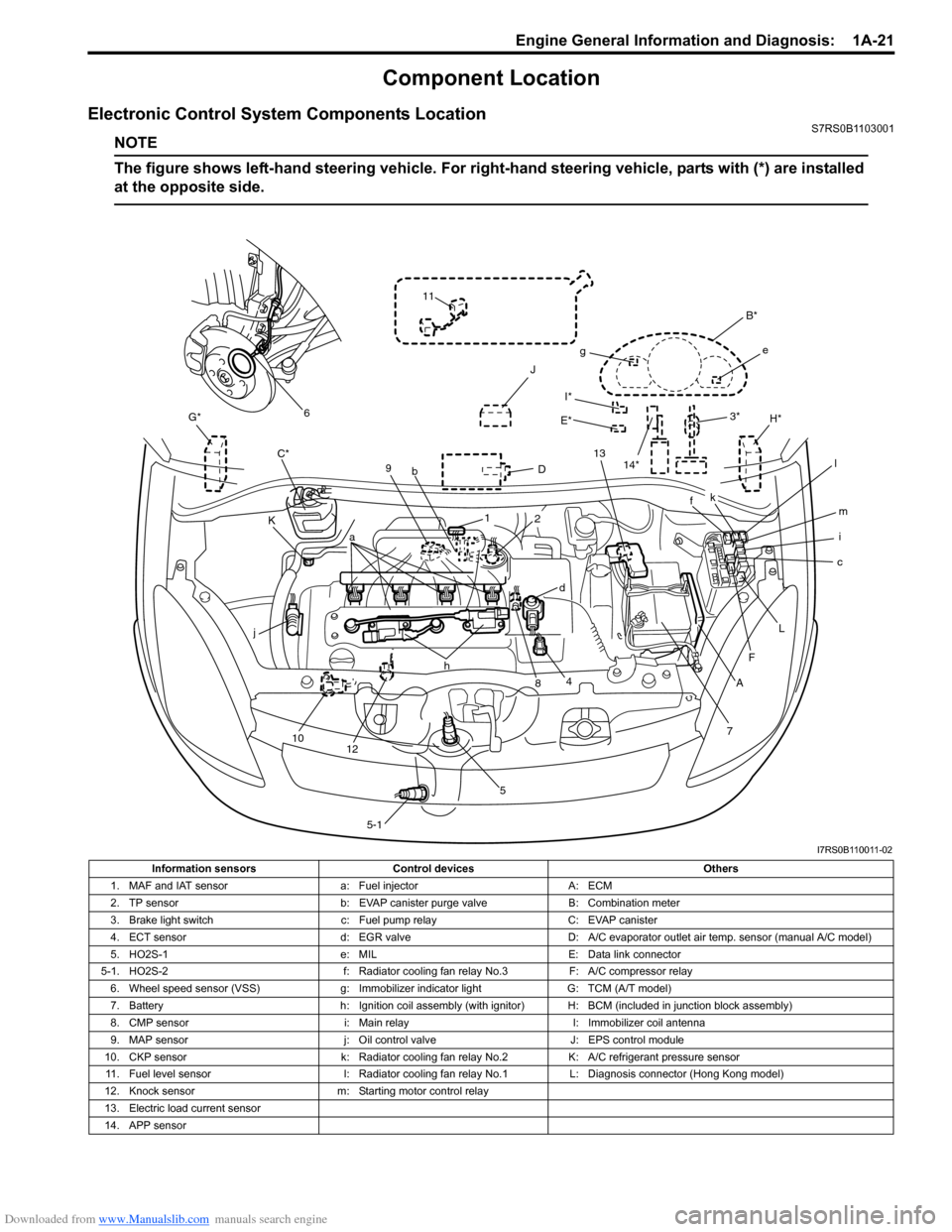
Component Location
Electronic Control System Components LocationS7RS0B1103001
NOTE
The figure shows left-hand steering vehicle. For right-hand steering vehicle, parts with (*) are installed
at the opposite side.
I*
E*
G*
D
K H*
J
C*
7
A
F
c
L
i m
f
B*
e
g
k
l
13
3*
4
j
10 12 h
58
a
9
b
1
5-1
d
2
11
6
14*
I7RS0B110011-02
Information sensors Control devices Others
1. MAF and IAT sensor a: Fuel injectorA: ECM
2. TP sensor b: EVAP canister purge valve B: Combination meter
3. Brake light switch c: Fuel pump relayC: EVAP canister
4. ECT sensor d: EGR valveD: A/C evaporator outlet air temp. sensor (manual A/C model)
5. HO2S-1 e: MILE: Data link connector
5-1. HO2S-2 f: Radiator cooling fan relay No.3F: A/C compressor relay
6. Wheel speed sensor (VSS) g: Immobilizer indicator lightG: TCM (A/T model)
7. Battery h: Ignition coil assembly (with ignitor) H: BCM (included in junction block assembly)
8. CMP sensor i: Main relayI: Immobilizer coil antenna
9. MAP sensor j: Oil control valveJ: EPS control module
10. CKP sensor k: Radiator cooling fan relay No.2K: A/C refrigerant pressure sensor
11. Fuel level sensor l: Radiator cooling fan relay No.1L: Diagnosis connector (Hong Kong model)
12. Knock sensor m: Starting motor control relay
13. Electric load current sensor
14. APP sensor
Page 93 of 1496
Downloaded from www.Manualslib.com manuals search engine Engine General Information and Diagnosis: 1A-43
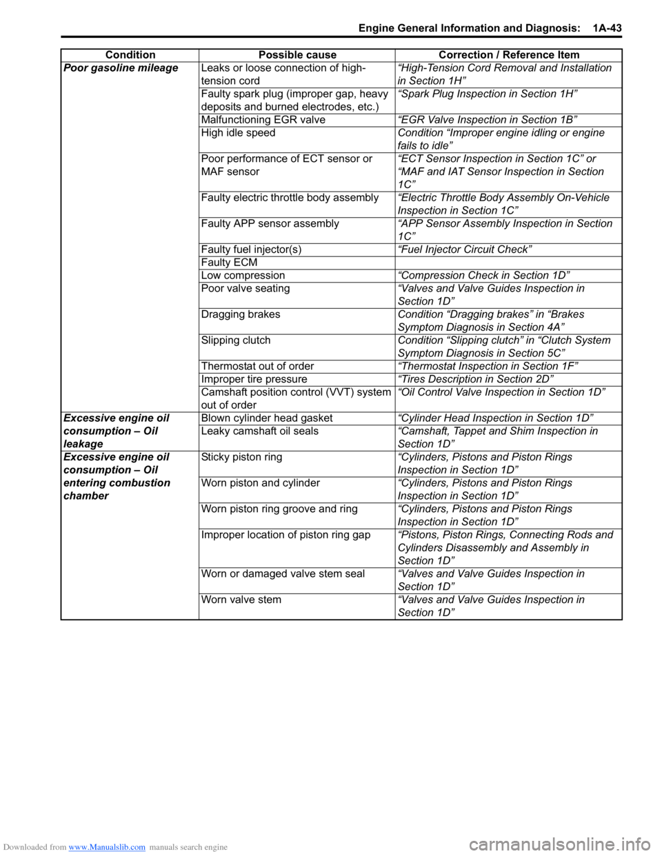
Poor gasoline mileageLeaks or loose connection of high-
tension cord “High-Tension Cord Removal and Installation
in Section 1H”
Faulty spark plug (improper gap, heavy
deposits and burned electrodes, etc.) “Spark Plug Inspection in Section 1H”
Malfunctioning EGR valve “EGR Valve Inspection in Section 1B”
High idle speed Condition “Improper engine idling or engine
fails to idle”
Poor performance of ECT sensor or
MAF sensor “ECT Sensor Inspection in Section 1C” or
“MAF and IAT Sensor Inspection in Section
1C”
Faulty electric throttle body assembly “Electric Throttle Body Assembly On-Vehicle
Inspection in Section 1C”
Faulty APP sensor assembly “APP Sensor Assembly Inspection in Section
1C”
Faulty fuel injector(s) “Fuel Injector Circuit Check”
Faulty ECM
Low compression “Compression Check in Section 1D”
Poor valve seating “Valves and Valve Guides Inspection in
Section 1D”
Dragging brakes Condition “Dragging brakes” in “Brakes
Symptom Diagnosis in Section 4A”
Slipping clutch Condition “Slipping clutch” in “Clutch System
Symptom Diagnosis in Section 5C”
Thermostat out of order “Thermostat Inspection in Section 1F”
Improper tire pressure “Tires Description in Section 2D”
Camshaft position control (VVT) system
out of order “Oil Control Valve Inspection in Section 1D”
Excessive engine oil
consumption – Oil
leakage Blown cylinder head gasket
“Cylinder Head Inspection in Section 1D”
Leaky camshaft oil seals “Camshaft, Tappet and Shim Inspection in
Section 1D”
Excessive engine oil
consumption – Oil
entering combustion
chamber Sticky piston ring
“Cylinders, Pistons and Piston Rings
Inspection in Section 1D”
Worn piston and cylinder “Cylinders, Pistons and Piston Rings
Inspection in Section 1D”
Worn piston ring groove and ring “Cylinders, Pistons and Piston Rings
Inspection in Section 1D”
Improper location of piston ring gap “Pistons, Piston Rings, Connecting Rods and
Cylinders Disassembly and Assembly in
Section 1D”
Worn or damaged valve stem seal “Valves and Valve Guides Inspection in
Section 1D”
Worn valve stem “Valves and Valve Guides Inspection in
Section 1D”
Condition Possible cause Correction / Reference Item
Page 383 of 1496
Downloaded from www.Manualslib.com manuals search engine Fuel System: 1G-8
Installation1) Install clamps to marked location on pipes. If clamp is deformed, its claw is bent or broken, replace it with
new one.
2) Install pipes with pipe clamps to vehicle.
3) Connect fuel hoses and pipes to each pipe referring to “Fuel Hose Disconnecting and Reconnecting”.
4) Connect negative cable at battery.
5) With engine OFF, turn igniti on switch to ON position
and check for fuel leaks.
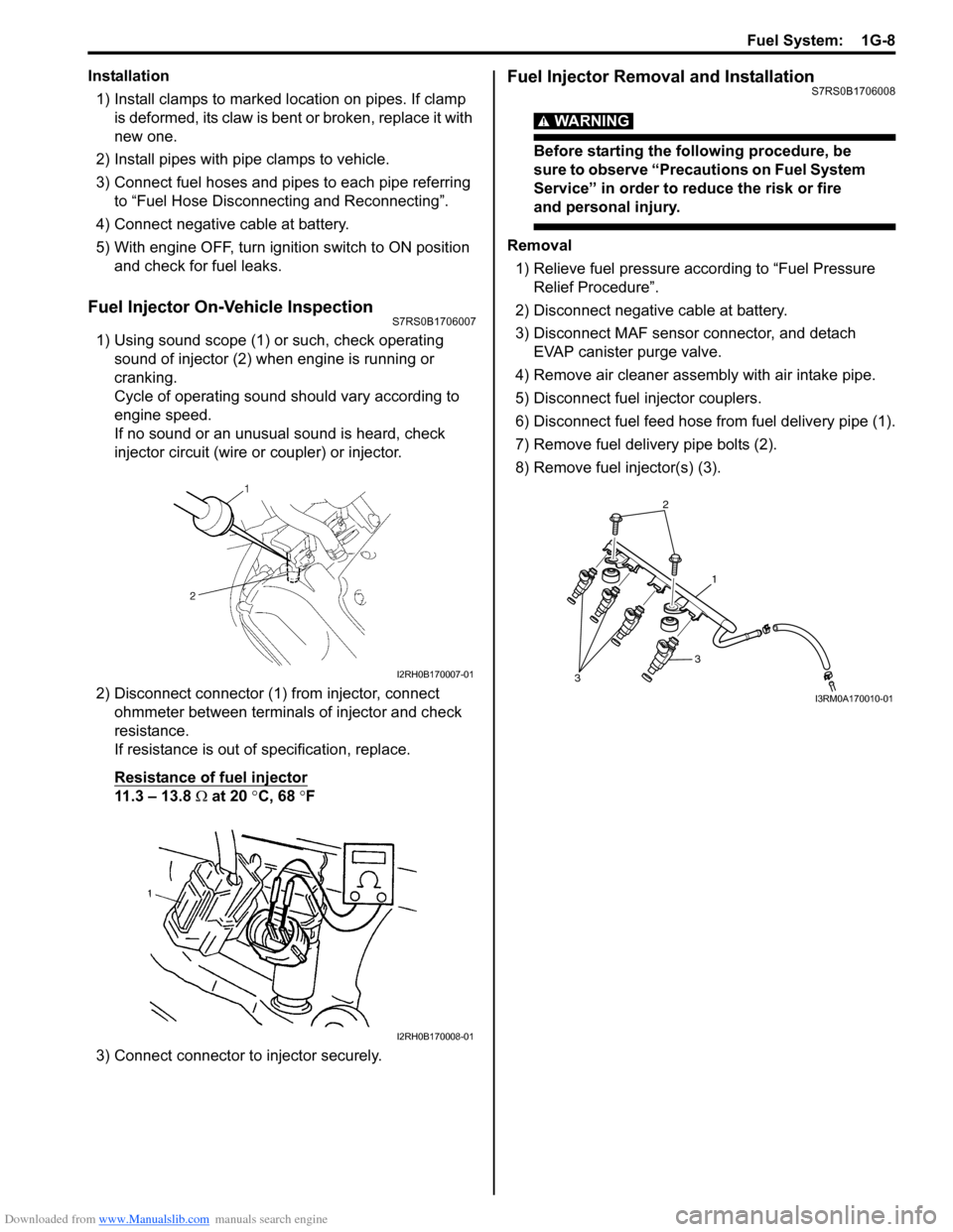
Fuel Injector On-Vehicle InspectionS7RS0B1706007
1) Using sound scope (1) or such, check operating sound of injector (2) when engine is running or
cranking.
Cycle of operating sound should vary according to
engine speed.
If no sound or an unusual sound is heard, check
injector circuit (wire or coupler) or injector.
2) Disconnect connector (1) from injector, connect ohmmeter between terminals of injector and check
resistance.
If resistance is out of specification, replace.
Resistance of fuel injector
11.3 – 13.8 Ω at 20 °C, 68 °F
3) Connect connector to injector securely.
Fuel Injector Removal and InstallationS7RS0B1706008
WARNING!
Before starting the following procedure, be
sure to observe “Precautions on Fuel System
Service” in order to reduce the risk or fire
and personal injury.
Removal 1) Relieve fuel pressure according to “Fuel Pressure Relief Procedure”.
2) Disconnect negative cable at battery.
3) Disconnect MAF sensor connector, and detach EVAP canister purge valve.
4) Remove air cleaner assembly with air intake pipe.
5) Disconnect fuel injector couplers.
6) Disconnect fuel feed hose from fuel delivery pipe (1).
7) Remove fuel delivery pipe bolts (2).
8) Remove fuel injector(s) (3).
I2RH0B170007-01
I2RH0B170008-01
2
1
3
3
I3RM0A170010-01
Page 395 of 1496

Downloaded from www.Manualslib.com manuals search engine Ignition System: 1H-3
Component Location
Ignition System Components LocationS7RS0B1803001
NOTE
The figure shows left-hand steering vehicle. For right-hand steering vehicle, parts with (*) are installed
at the opposite side.
16*
1
2
14
7
5 12 11
410
6
89
3 13*
15
17
I6RS0C180001-01
1. ECM 7. ECT sensor13. Data link connector
2. Ignition coil assembly for No.1 and No.4 spark plugs 8. MAF and IAT sensor 14. Battery fuse box
3. Ignition coil assembly for No.2 and No.3 spark plugs 9. Electric throttle body 15. Relay box
4. CMP sensor 10. Wheel speed sensor (VSS) 16. Junction block assembly
5. CKP sensor 11. High-tension cords
6. MAP sensor 12. Knock sensor
Page 426 of 1496
Downloaded from www.Manualslib.com manuals search engine 1K-3 Exhaust System:
Exhaust Manifold Removal and InstallationS7RS0B1B06002
Removal
WARNING!
To avoid danger of being burned, do not
service exhaust system while it is still hot.
Service should be performed after system
cools down.
1) Disconnect negative cable at battery.
2) Remove engine cover.
3) Remove front bumper with front grille referring to
“Front Bumper and Rear Bumper Components in
Section 9K”.
4) Remove radiator referring to “Radiator Removal and Installation in Section 1F ” for equipped with A/C.
5) With hose connected, detach A/C condenser from vehicle body for equipped with A/C.
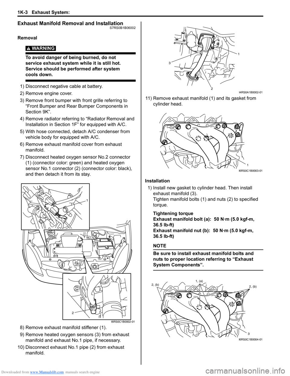
6) Remove exhaust manifold cover from exhaust manifold.
7) Disconnect heated oxygen sensor No.2 connector (1) (connector color: green) and heated oxygen
sensor No.1 connector (2) (connector color: black),
and then detach it from its stay.
8) Remove exhaust manifold stiffener (1).
9) Remove heated oxygen sensors (3) from exhaust manifold and exhaust No.1 pipe, if necessary.
10) Disconnect exhaust No.1 pipe (2) from exhaust manifold. 11) Remove exhaust manifold (1) and its gasket from
cylinder head.
Installation 1) Install new gasket to cylinder head. Then install exhaust manifold (3).
Tighten manifold bolts (1) and nuts (2) to specified
torque.
Tightening torque
Exhaust manifold bolt (a): 50 N·m (5.0 kgf-m,
36.5 lb-ft)
Exhaust manifold nut (b): 50 N·m (5.0 kgf-m,
36.5 lb-ft)
NOTE
Be sure to install exhaust manifold bolts and
nuts to proper location referring to “Exhaust
System Components”.
1
2
I6RS0C1B0002-01
1
2
3
I4RS0A1B0002-01
1
I6RS0C1B0003-01
2, (b) 2, (b)
3
1, (a)
I6RS0C1B0004-01