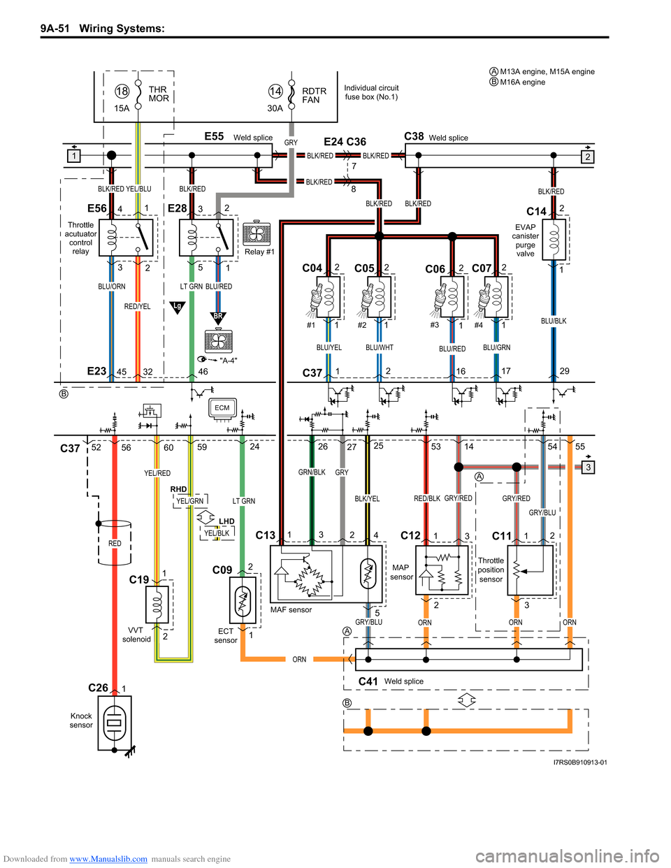
2007 SUZUKI SWIFT Knock sensor wiring
[x] Cancel search: Knock sensor wiringPage 157 of 1496

Downloaded from www.Manualslib.com manuals search engine Engine General Information and Diagnosis: 1A-107
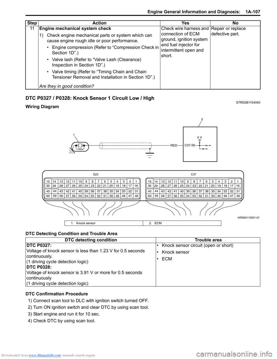
DTC P0327 / P0328: Knock Sensor 1 Circuit Low / HighS7RS0B1104040
Wiring Diagram
DTC Detecting Condition and Trouble Area
DTC Confirmation Procedure1) Connect scan tool to DLC with ignition switch turned OFF.
2) Turn ON ignition switch and clear DTC by using scan tool.
3) Start engine and run it for 10 sec.
4) Check DTC by using scan tool. 11
Engine mechanical system check
1) Check engine mechanical parts or system which can
cause engine rough idle or poor performance.
• Engine compression (Refer to “Compression Check in Section 1D”.)
• Valve lash (Refer to “Valve Lash (Clearance) Inspection in Section 1D”.)
• Valve timing (Refer to “Timing Chain and Chain Tensioner Removal and Installation in Section 1D”.)
Are they in good condition? Check wire harness and
connection of ECM
ground, ignition system
and fuel injector for
intermittent open and
short.
Repair or replace
defective part.
Step
Action YesNo
E23 C37
34
1819
567
1011
17
20
47 46
495051
2122
52 16
25 9
24
14
29
55
57 54 53
59
60 58 2
262728
15
30
56 4832 31
34353637
40
42 39 38
44
45 43 41 331
1213
238
34
1819
567
1011
17
20
47 46
495051
2122
52 16
25 9
24
14
29
55
57 54 53
59
60 58 2
262728
15
30
56 4832 31
34353637
40
42 39 38
44
45 43 41 331
1213
238
1 2
REDC37-56
5 V
I4RS0A110031-01
1. Knock sensor
2. ECM
DTC detecting condition Trouble area
DTC P0327:
Voltage of knock sensor is less than 1.23 V for 0.5 seconds
continuously.
(1 driving cycle detection logic)
DTC P0328:
Voltage of knock sensor is 3.91 V or more for 0.5 seconds
continuously
(1 driving cycle detection logic) • Knock sensor circuit (open or short)
• Knock sensor
•ECM
Page 159 of 1496

Downloaded from www.Manualslib.com manuals search engine Engine General Information and Diagnosis: 1A-109
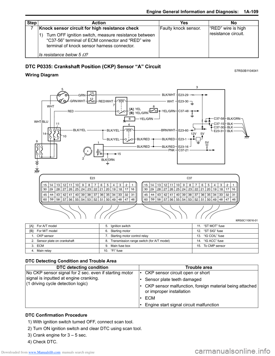
DTC P0335: Crankshaft Position (CKP) Sensor “A” CircuitS7RS0B1104041
Wiring Diagram
DTC Detecting Condition and Trouble Area
DTC Confirmation Procedure1) With ignition switch turned OFF, connect scan tool.
2) Turn ON ignition switch and clear DTC using scan tool.
3) Crank engine for 3 – 5 sec.
4) Check DTC. 7
Knock sensor circuit for high resistance check
1) Turn OFF ignition switch, measure resistance between
“C37-56” terminal of ECM connector and “RED” wire
terminal of knock sensor harness connector.
Is resistance below 5
Ω? Faulty knock sensor. “RED” wire is high
resistance circuit.
Step
Action YesNo
E23 C37
34
1819
567
1011
17
20
47 46
495051
2122
52 16
25 9
24
14
29
55
57 54 53
59
60 58 2
262728
15
30
56 4832 31
34353637
40
42 39 38
44
45 43 41 331
1213
238
34
1819
567
1011
17
20
47 46
495051
2122
52 16
25 9
24
14
29
55
57 54 53
59
60 58 2
262728
15
30
56 4832 31
34353637
40
42 39 38
44
45 43 41 331
1213
238
12V
5V
BLK/RED
BLK/RED
BLK/YELBLK/YEL
BLK/YEL
BRN/WHT
5
9 4
13
3
C37-30C37-15
C37-58
E23-31
BLK/ORN
BLKBLKBLK
10
BLK/RED
BLK/RED
E23-16
E23-60
E23-1
BLK/ORN
1
15
C37-21 5V
7RED/WHTGRN/WHT
GRN
RED
BLK/WHT
YEL/GRN
YEL/GRN
WHT
[A]: YEL
[B]: YEL/GRN
68
12
11
14
PNK
2
WHT
WHT/BLU
C37-48
E23-30
E23-29
I6RS0C110016-01
[A]: For A/T model 5. Ignition switch 11. “ST MOT” fuse
[B]: For M/T model 6. Starting motor 12. “ST SIG” fuse
1. CKP sensor 7. Starting motor control relay 13. “IG COIL” fuse
2. Sensor plate on crankshaft 8. Transmission range switch (for A/T model) 14. “IG ACC” fuse
3. ECM 9. Main fuse box 15. To CMP sensor
4. Main relay 10. “FI” fuse
DTC detecting condition Trouble area
No CKP sensor signal for 2 se c. even if starting motor
signal is inputted at engine cranking.
(1 driving cycle detection logic) • CKP sensor circuit open or short
• Sensor plate teeth damaged
• CKP sensor malfunction, foreign material being attached
or improper installation
•ECM
• Engine start signal circuit malfunction
Page 394 of 1496

Downloaded from www.Manualslib.com manuals search engine 1H-2 Ignition System:
Schematic and Routing Diagram
Ignition System Wiring Circuit DiagramS7RS0B1802001
E23-60
E23-29 12V 5V
5V
E23-1
E23-16
BLK/WHT
BLK/RED
BLK/RED BLK/RED
BLK/YELBLK/YEL
BLK/YEL
GRN
BLKWHT
WHT
BRN/WHT
BLK/ORN
BLK
BLK
C37-20
BLK/RED
PNK
5V
C37-21
BLK/WHT
7
3 4
1
12 5
6
2
11
8
9
10
GRN/YEL
GRN/WHT
C37-6
C37-5 5V
5V
RED/YEL
C37-58
C37-15
C37-30
E23
C37
34
1819
567
1011
17
20
47 46
495051
2122
52 16
25 9
24
14
29
55
57 54 53
59
60 58 2
262728
15
30
56 4832 31
34353637
40
42 39 38
44
45 43 41 331
1213
238
34
1819
567
1011
17
20
47 46
495051
2122
52 16
25 9
24
14
29
55
57 54 53
59
60 58 2
262728
15
30
56 4832 31
34353637
40
42 39 38
44
45 43 41 331
1213
238
13
14
15
16
17
50A50A80A
BLK/ORN
E23-31 BLK
I4RS0B180001-01
1. Ignition switch 7. No.1 spark plug 13. Individual circuit fuse box
No.1
2. Main relay 8. No.2 spark plug 14. “IG ACC” fuse
3. Ignition coil assembly for No.1 and No.4 spark plugs 9. No.3 spark plug 15. “FI” fuse
4. Ignition coil assembly for No.2 and No.3 spark plugs 10. No.4 spark plug 16. Junction block assembly
5. CMP sensor 11. Sensed information (MAP sensor, ECT sensor, MAF and IAT
sensor, TP sensor, Knock sensor, VSS, Electric load signal,
Engine start signal) 17. “IG COIL” fuse
6. CKP sensor 12. Battery fuse box
Page 1182 of 1496

Downloaded from www.Manualslib.com manuals search engine 9A-11 Wiring Systems:
C: Engine harnessNo./Color Connective position No./Color Connective positionC01/GRY IAC valve C22/- Generator #2
C02/GRY IG Coil #1 C23/BLK Starting motor #1
C03/GRY IG Coil #2 C24/- Starting motor #2
C04/GRY Fuel injector #1 C25/GR Y VSS (Vehicle speed sensor)
C05/GRY Fuel injector #2 C26/GRY Knock sensor
C06/GRY Fuel injector #3 C27/BLU (A/
T) Input shaft speed sensor
C07/GRY Fuel injector #4 C28/GRY
(A/T) Trans axle range sensor
C08/BLK or GRY CMP sensor C29/GRY
(A/T) Shift solenoid
C09/BLK ECT sensor C30/BLK
(M/T) Back-up light switch
C10/GRY EGR stepper motor C31/- Main fuse box C11/BLK Throttle position sensor C32/GRY
(IF EQPD) Current sensor
C12/BLK MAP sensor C33/- Main fuse box
C13/BLK MAF sensor C34/N (A/T) TCM
C14/BLK EVAP canister purge valve C35/N (A/T) TCM
C15/GRY Heated oxygen sensor #1 C36/N Main harness (To E24)
C16/GRN Heated oxygen sensor #2 C37/GRY ECM C17/BLK A/C compressor C38/- Weld splice C18/N Oil pressure switch C39/- Weld splice
C19/BLU VVT solenoid C40/- Weld splice
C20/GRY CKP sensor C41/- Weld splice
C21/GRY or BLK Generator #1
Page 1184 of 1496

Downloaded from www.Manualslib.com manuals search engine 9A-13 Wiring Systems:
C: Engine harness
D: Oil pressure switch wireNo./Color Connective position No./Color Connective position
C02/GRY IG Coil #1 C24/- Starting motor #2
C03/GRY IG Coil #2 C23/BLK Starting motor #1
C04/GRY Fuel injector #1 C25/GRY
(A/T) VSS (Vehicle speed sensor)
C05/GRY Fuel injector #2 C26/GRY Knock shaft speed sensor
C06/GRY Fuel injector #3 C27/BLU (A/
T) Input shaft speed sensor
C07/GRY Fuel injector #4 C28/GRY
(A/T) Trans axle range sensor
C08/BLK CMP sensor C29/GRY
(A/T) Shift solenoid
C09/BLK ECT sensor C30/BLK
(M/T) Back-up light switch
C10/GRY EGR stepper motor C31/- Main fuse box C12/BLK MAP sensor C32/GRY Current sensor
C13/BLK MAF sensor C33/- Main fuse box
C14/BLK EVAP canister purge valve C34/N (A/T) TCM
C15/BLK Heated oxygen sensor #1 C35/N (A/T) TCM
C16/GRN Heated oxygen sensor #2 C36/N Main harness (To E24) C17/BLK A/C compressor C37/GRY ECM C18/N Oil pressure switch wire (To D02) C38/- Weld splice
C19/BLU VVT solenoid C39/- Weld splice
C20/GRY CKP sensor C40/- Weld splice C21/BLK Generator #1 C42/BLK Electric throttle body C22/- Generator #2
No./Color Connective position No./ColorConnective position
D01/N Oil pressure switch D02/GRY Engine harness (To C18)
Page 1222 of 1496

Downloaded from www.Manualslib.com manuals search engine 9A-51 Wiring Systems:
Throttle
acutuator controlrelay
4532
BLK/REDYEL/BLU
1
243E562
135E28
15A THR
MOR
18
M13A engine, M15A engine
M16A engine
A
B
A
A
B
B
2C09
LT GRN
1
C12
C13
C11
E23
C37
C37
Knock
sensor
C19
ECM
C042
1C052
1C062
1C072
1
#2
#1 #3
#4
BLU/REDBLU/WHTBLU/YELBLU/GRN
BLK/RED
BLU/BLK
EVAP
canister purgevalve
C14
ECT
sensor
ORN
MAF sensor
MAP
sensorThrottle
position sensor
Weld spliceC41
ORNORNORN
LT GRNBLU/REDBLU/ORN
RED/YEL
GRY
"A-4"
Lg
30A RDTR
FAN
14
Relay #1
BR
46
1
2
1
29
17
16
2
1
2425
26 27
4
3
2
1
5
1
2 3
1
32
2
3
54 55
RED/BLKGRY/REDGRY/RED
GRY/BLU
53 14
E24 C36
8
7
C26
RED
1
56
VVT
solenoid
1
2
60 59
BLK/RED
E55Weld spliceC38Weld splice
BLK/REDBLK/RED
BLK/REDBLK/RED
BLK/RED
GRN/BLKGRY
BLK/YEL
GRY/BLU
52
YEL/RED
Individual circuit
fuse box (No.1)
YEL/GRN
YEL/BLK
RHD
LHD
I7RS0B910913-01