2007 SUZUKI SWIFT Signals
[x] Cancel search: SignalsPage 663 of 1496
Downloaded from www.Manualslib.com manuals search engine Automatic Transmission/Transaxle: 5A-19
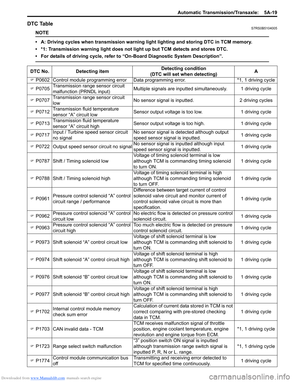
DTC TableS7RS0B5104005
NOTE
• A: Driving cycles when transmission warning light lighting and storing DTC in TCM memory.
• *1: Transmission warning light does not light up but TCM detects and stores DTC.
• For details of driving cycle, refer to “On-Board Diagnostic System Description”.
DTC No.Detecting item Detecting condition
(DTC will set when detecting) A
�) P0602 Control module programming error D ata programming error. *1, 1 driving cycle
�) P0705 Transmission range sensor circuit
malfunction (PRNDL input) Multiple signals are inputted
simultaneously. 1 driving cycle
�) P0707 Transmission range sensor circuit
low No sensor signal is inputted.
2 driving cycles
�) P0712 Transmission fluid temperature
sensor “A” circuit low Sensor output voltage is too low.
1 driving cycle
�) P0713 Transmission fluid temperature
sensor “A” circuit high Sensor output voltage is too high.
1 driving cycle
�) P0717 Input / Turbine speed sensor circuit
no signal No sensor signal is detected although output
speed sensor signal is inputted.
1 driving cycle
�) P0722 Output speed sensor circuit no signal No sensor signal is inputted although input
speed sensor signal is inputted. 1 driving cycle
�) P0787 Shift / Timing solenoid low Voltage of timing solenoid terminal is low
although TCM is commanding timing solenoid
to turn ON. 1 driving cycle
�) P0788 Shift / Timing solenoid high Voltage of timing solenoid terminal is high
although TCM is commanding timing solenoid
to turn OFF. 1 driving cycle
�) P0961 Pressure control solenoid “A” control
circuit range / performance Difference between target current of control
solenoid valve circuit and monitor current of
control solenoid valve circuit is more than
specification.
1 driving cycle
�) P0962 Pressure control solenoid “A” control
circuit low No electric flow is detected on pressure control
solenoid circuit.
1 driving cycle
�) P0963 Pressure control solenoid “A” control
circuit high Too much electric flow is detected on pressure
control solenoid circuit.
1 driving cycle
�) P0973 Shift solenoid “A” control circuit low Voltage of shift solenoid terminal is low
although TCM is commanding shift solenoid to
turn ON. 1 driving cycle
�) P0974 Shift solenoid “A” control circuit high Voltage of shift solenoid terminal is high
although TCM is commanding shift solenoid to
turn OFF. 1 driving cycle
�) P0976 Shift solenoid “B” control circuit low Voltage of shift solenoid terminal is low
although TCM is commanding shift solenoid to
turn ON. 1 driving cycle
�) P0977 Shift solenoid “B” control circuit high Voltage of shift solenoid terminal is high
although TCM is commanding shift solenoid to
turn OFF. 1 driving cycle
�) P1702 Internal control module memory
check sum error Calculation of current data stored in TCM is not
correct comparing with pre-stored checking
data in TCM.
1 driving cycle
�) P1703 CAN invalid data - TCM TCM receives malfunction signal of throttle
position
, engine coolan t temperature, engine
revolution and engine torque from ECM. *1, 1 driving cycle
�) P1723 Range select switch malfunction “3” position switch ON signal is inputted
although transmission range switch signal is
inputted P, R, N or L. range. *1, 1 driving cycle
�) P1774 Control module communication bus
off Transmitting and receiving error detected to
TCM for specified time continuously.
1 driving cycle
Page 669 of 1496
Downloaded from www.Manualslib.com manuals search engine Automatic Transmission/Transaxle: 5A-25
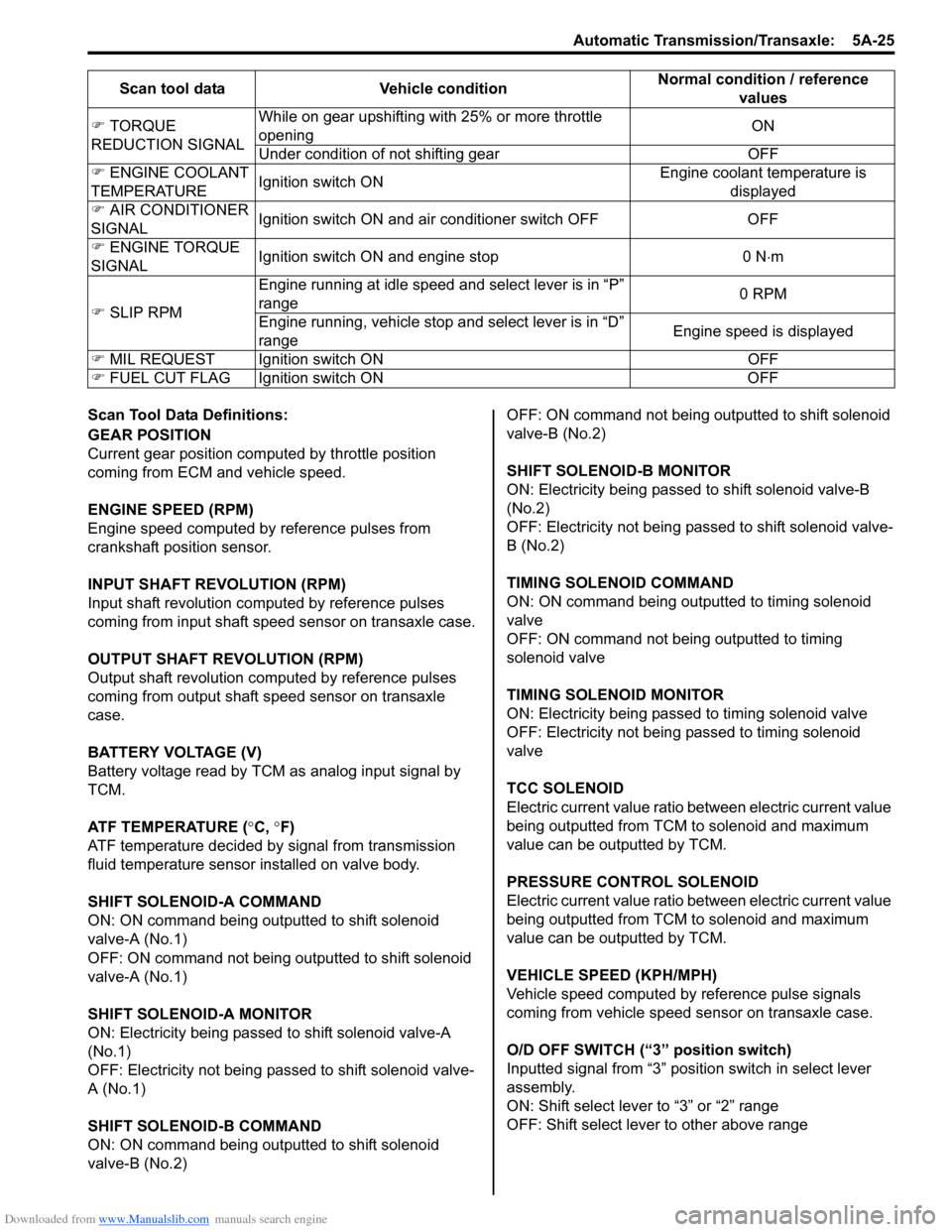
Scan Tool Data Definitions:
GEAR POSITION
Current gear position computed by throttle position
coming from ECM and vehicle speed.
ENGINE SPEED (RPM)
Engine speed computed by reference pulses from
crankshaft position sensor.
INPUT SHAFT REVOLUTION (RPM)
Input shaft revolution computed by reference pulses
coming from input shaft speed sensor on transaxle case.
OUTPUT SHAFT REVOLUTION (RPM)
Output shaft revolution computed by reference pulses
coming from output shaft speed sensor on transaxle
case.
BATTERY VOLTAGE (V)
Battery voltage read by TCM as analog input signal by
TCM.
ATF TEMPERATURE (°C, °F)
ATF temperature decided by signal from transmission
fluid temperature sensor installed on valve body.
SHIFT SOLENOID-A COMMAND
ON: ON command being outputted to shift solenoid
valve-A (No.1)
OFF: ON command not being outputted to shift solenoid
valve-A (No.1)
SHIFT SOLENOID-A MONITOR
ON: Electricity being passed to shift solenoid valve-A
(No.1)
OFF: Electricity not being passed to shift solenoid valve-
A (No.1)
SHIFT SOLENOID-B COMMAND
ON: ON command being outputted to shift solenoid
valve-B (No.2) OFF: ON command not being outputted to shift solenoid
valve-B (No.2)
SHIFT SOLENOID-B MONITOR
ON: Electricity being passed to shift solenoid valve-B
(No.2)
OFF: Electricity not being passed to shift solenoid valve-
B (No.2)
TIMING SOLENOID COMMAND
ON: ON command being outputted to timing solenoid
valve
OFF: ON command not being outputted to timing
solenoid valve
TIMING SOLENOID MONITOR
ON: Electricity being passed to timing solenoid valve
OFF: Electricity not being passed to timing solenoid
valve
TCC SOLENOID
Electric current value ratio between electric current value
being outputted from TCM to solenoid and maximum
value can be outputted by TCM.
PRESSURE CONTROL SOLENOID
Electric current value ratio between electric current value
being outputted from TCM to solenoid and maximum
value can be outputted by TCM.
VEHICLE SPEED (KPH/MPH)
Vehicle speed computed by reference pulse signals
coming from vehicle speed sensor on transaxle case.
O/D OFF SWITCH (“3” position switch)
Inputted signal from “3” position switch in select lever
assembly.
ON: Shift select lever to “3” or “2” range
OFF: Shift select lever to other above range
�)
TORQUE
REDUCTION SIGNAL While on gear upshifting with 25% or more throttle
opening
ON
Under condition of not shifting gear OFF
�) ENGINE COOLANT
TEMPERATURE Ignition switch ON Engine coolant temperature is
displayed
�) AIR CONDITIONER
SIGNAL Ignition switch ON and air conditioner switch OFF OFF
�) ENGINE TORQUE
SIGNAL Ignition switch ON and engine stop 0 N
⋅m
�) SLIP RPM Engine running at idle speed
and select lever is in “P”
range 0 RPM
Engine running, vehicle stop and select lever is in “D”
range Engine speed is displayed
�) MIL REQUEST Ignition switch ON OFF
�) FUEL CUT FLAG Ignition switch ON OFFScan tool data Vehicle condition
Normal condition / reference
values
Page 689 of 1496
Downloaded from www.Manualslib.com manuals search engine Automatic Transmission/Transaxle: 5A-45
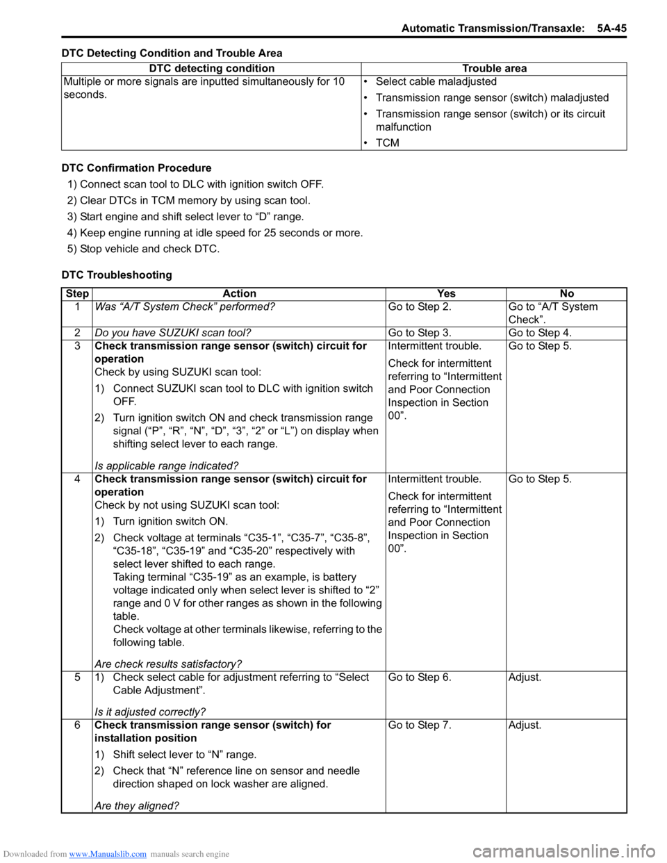
DTC Detecting Condition and Trouble Area
DTC Confirmation Procedure1) Connect scan tool to DLC with ignition switch OFF.
2) Clear DTCs in TCM memo ry by using scan tool.
3) Start engine and shift select lever to “D” range.
4) Keep engine running at idle speed for 25 seconds or more.
5) Stop vehicle and check DTC.
DTC Troubleshooting DTC detecting condition Trouble area
Multiple or more signals are inputted simultaneously for 10
seconds. • Select cable maladjusted
• Transmission range sensor (switch) maladjusted
• Transmission range sensor (switch) or its circuit
malfunction
•TCM
Step Action YesNo
1 Was “A/T System Check” performed? Go to Step 2.Go to “A/T System
Check”.
2 Do you have SUZUKI scan tool? Go to Step 3.Go to Step 4.
3 Check transmission range sensor (switch) circuit for
operation
Check by using SUZUKI scan tool:
1) Connect SUZUKI scan tool to DLC with ignition switch
OFF.
2) Turn ignition switch ON and check transmission range signal (“P”, “R”, “N”, “D”, “3”, “2” or “L”) on display when
shifting select lever to each range.
Is applicable range indicated? Intermittent trouble.
Check for intermittent
referring to “Intermittent
and Poor Connection
Inspection in Section
00”.
Go to Step 5.
4 Check transmission range sensor (switch) circuit for
operation
Check by not using SUZUKI scan tool:
1) Turn ignition switch ON.
2) Check voltage at terminals “C35-1”, “C35-7”, “C35-8”,
“C35-18”, “C35-19” and “C35-20” respectively with
select lever shifted to each range.
Taking terminal “C35-19” as an example, is battery
voltage indicated only when se lect lever is shifted to “2”
range and 0 V for other ranges as shown in the following
table.
Check voltage at other terminals likewise, referring to the
following table.
Are check results satisfactory? Intermittent trouble.
Check for intermittent
referring to “Intermittent
and Poor Connection
Inspection in Section
00”.
Go to Step 5.
5 1) Check select cable for adjustment referring to “Select Cable Adjustment”.
Is it adjusted correctly? Go to Step 6.
Adjust.
6 Check transmission range sensor (switch) for
installation position
1) Shift select lever to “N” range.
2) Check that “N” reference line on sensor and needle
direction shaped on lock washer are aligned.
Are they aligned? Go to Step 7.
Adjust.
Page 695 of 1496
Downloaded from www.Manualslib.com manuals search engine Automatic Transmission/Transaxle: 5A-51
DTC P0717: Input / Turbine Speed Sensor “A” Circuit MalfunctionS7RS0B5104027
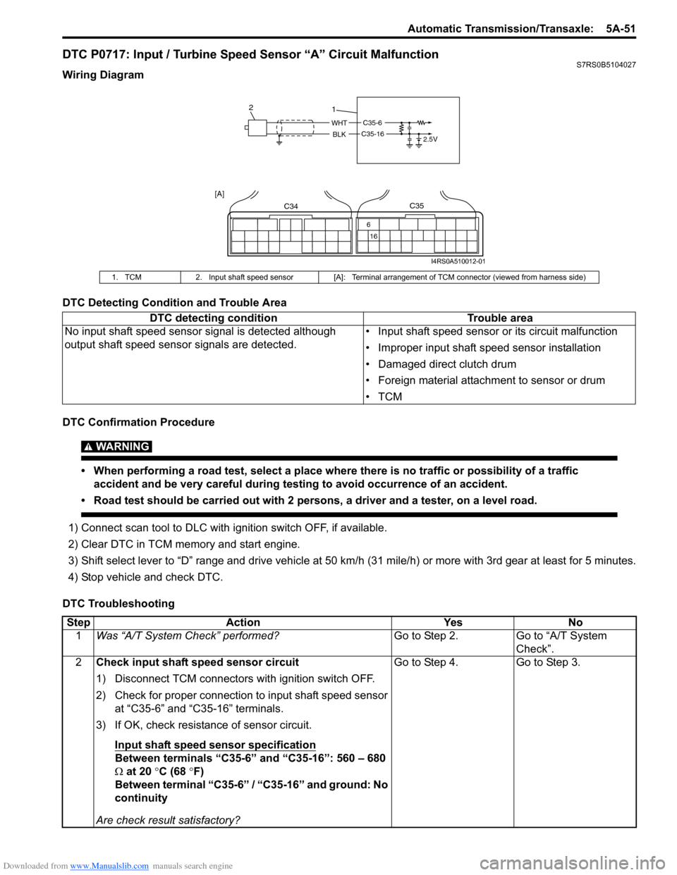
Wiring Diagram
DTC Detecting Condition and Trouble Area
DTC Confirmation Procedure
WARNING!
• When performing a road test, select a place where there is no traffic or possibility of a traffic accident and be very careful during testing to avoid occurrence of an accident.
• Road test should be carried out with 2 persons, a driver and a tester, on a level road.
1) Connect scan tool to DLC with ig nition switch OFF, if available.
2) Clear DTC in TCM memory and start engine.
3) Shift select lever to “D” range and drive vehicle at 50 km /h (31 mile/h) or more with 3rd gear at least for 5 minutes.
4) Stop vehicle and check DTC.
DTC Troubleshooting
1. TCM 2. Input shaft speed sensor [A]: Terminal arrangement of TCM connector (viewed from harness side)
DTC detecting condition Trouble area
No input shaft speed sensor signal is detected although
output shaft speed sens or signals are detected. • Input shaft speed sensor or its circuit malfunction
• Improper input shaft speed sensor installation
• Damaged direct clutch drum
• Foreign material attachment to sensor or drum
•TCM
C35-6
2.5VWHT
BLKC35-16
1
2
C34
16
6
C35
[A]
I4RS0A510012-01
Step
Action YesNo
1 Was “A/T System Check” performed? Go to Step 2.Go to “A/T System
Check”.
2 Check input shaft speed sensor circuit
1) Disconnect TCM connectors with ignition switch OFF.
2) Check for proper connection to input shaft speed sensor
at “C35-6” and “C35-16” terminals.
3) If OK, check resistance of sensor circuit.
Input shaft speed sensor specification
Between terminals “C35-6” and “C35-16”: 560 – 680
Ω at 20 °C (68 °F)
Between terminal “C35-6” / “C35-16” and ground: No
continuity
Are check result satisfactory? Go to Step 4. Go to Step 3.
Page 696 of 1496

Downloaded from www.Manualslib.com manuals search engine 5A-52 Automatic Transmission/Transaxle:
DTC P0722: Output Speed Sensor Circuit No SignalS7RS0B5104028
Wiring Diagram
DTC Detecting Condition and Trouble Area
DTC Confirmation Procedure
WARNING!
• When performing a road test, select a place where there is no traffic or possibility of a traffic
accident and be very careful during testing to avoid occurrence of an accident.
• Road test should be carried out with 2 persons, a driver and a tester, on a level road.
3 Inspect input shaft speed sensor
1) Inspect input shaft speed sensor referring to “Input Shaft
Speed Sensor Inspection”.
Is result satisfactory? “WHT” or “BLK” circuit
open or short.
Replace input shaft
speed sensor.
4 Check visually input shaft speed sensor and direct
clutch drum for the following
• No damage
• No foreign material attached
• Correct installation
Are they in good condition? Intermittent trouble or
faulty TCM.
Check for intermittent
referring to “Intermittent
and Poor Connection
Inspection in Section
00”.
If OK, substitute a
known-good TCM and
recheck.
Clean, repair or replace.
Step Action Yes No
I2RH0B510020-01
1. TCM
3. To ECM
2. Output shaft speed sensor [A]: Terminal arrangement of TCM connector (viewed from harness side)
DTC detecting condition Trouble area
No output shaft speed sensor signal is detected although
input shaft speed sensor signal s are detected while vehicle is
running at 5 km/h (3 mile/h) or more in vehicle speed with
“D”, “2” or “L” range. • Output shaft speed sensor or its circuit malfunction
• Damaged sensor gear (driven gear)
• Damaged output shaft speed sensor drive gear
•TCM
IG112V
PPLC35-25
2
C34
25
C35
[A]
1
BLK/RED
BLK/ORN
3
I4RS0B510005-01
Page 884 of 1496

Downloaded from www.Manualslib.com manuals search engine 6C-2 Power Assisted Steering System:
General Description
P/S System DescriptionS7RS0B6301001
This power steering (P/S) system consists of a P/S control module (3), a torque sensor (4), a motor (5). In this system,
the P/S control module determines the level and direction of the assist force for the steering wheel (1) according to the
signals from the torque sensor and vehicle speed signal from ECM. The P/S control module runs the motor so as to
assist the operation of the steering wheel.
The P/S control module diagnoses troubles which may occur in the area including the following components when the
ignition switch is ON and the engine is running. When the P/S control module detects any malfunction, it stops the
motor operation.
• Torque sensor
• Vehicle speed signal
• Engine speed signal
• P/S motor
• P/S control module.
2. Steering column 7. Battery9. ABS/ESP® control module
6. Steering gear case assembly 8. ECM10. Wheel speed sensor (right-front, left-front)
7
3
9
10
10
1
2
4
5
6
8
I7RS0B630001-01
Page 910 of 1496
Downloaded from www.Manualslib.com manuals search engine 6C-28 Power Assisted Steering System:
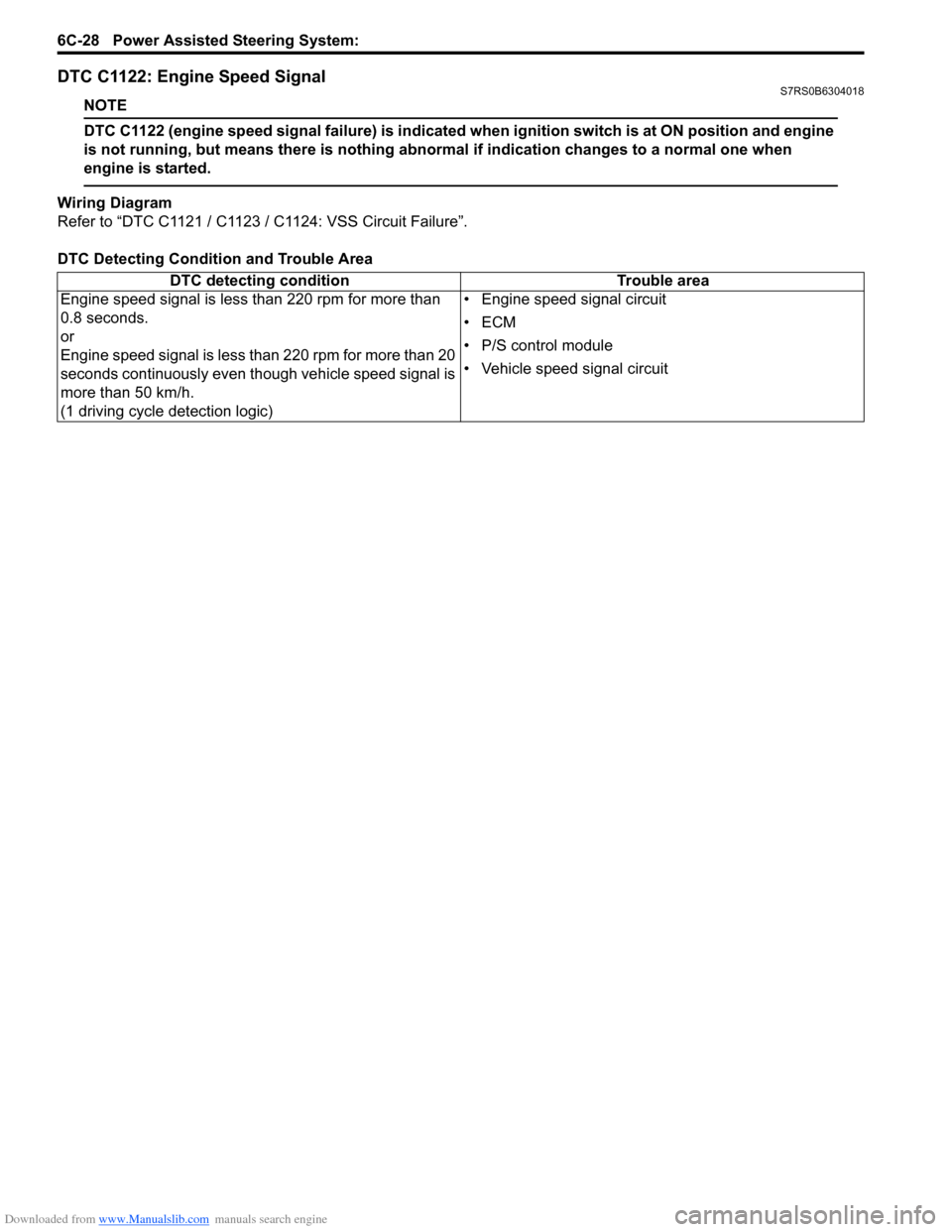
DTC C1122: Engine Speed SignalS7RS0B6304018
NOTE
DTC C1122 (engine speed signal failure) is indicated when ignition switch is at ON position and engine
is not running, but means there is nothing abnormal if indication changes to a normal one when
engine is started.
Wiring Diagram
Refer to “DTC C1121 / C1123 / C1124: VSS Circuit Failure”.
DTC Detecting Condition and Trouble Area DTC detecting condition Trouble area
Engine speed signal is less than 220 rpm for more than
0.8 seconds.
or
Engine speed signal is less than 220 rpm for more than 20
seconds continuously even though vehicle speed signal is
more than 50 km/h.
(1 driving cycle detection logic) • Engine speed signal circuit
•ECM
• P/S control module
• Vehicle speed signal circuit
Page 952 of 1496
Downloaded from www.Manualslib.com manuals search engine 7B-4 Air Conditioning System: Manual Type
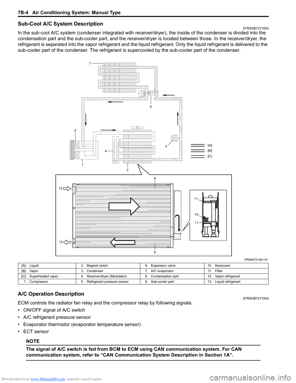
Sub-Cool A/C System DescriptionS7RS0B7211003
In the sub-cool A/C system (condenser integrated with receiver/dryer), the inside of the condenser is divided into the
condensation part and the sub-cooler part, and the receiver/dryer is located between those. In the receiver/dryer, the
refrigerant is separated into the vapor refrigerant and the liqui d refrigerant. Only the liquid refrigerant is delivered to the
sub-cooler part of the condenser. The refrigerant is supercooled by the sub-cooler part of the condenser.
A/C Operation DescriptionS7RS0B7211004
ECM controls the radiator fan relay and the compressor relay by following signals.
• ON/OFF signal of A/C switch
• A/C refrigerant pressure sensor
• Evaporator thermistor (evaporator temperature sensor)
• ECT sensor
NOTE
The signal of A/C swit ch is fed from BCM to ECM usin g CAN communication system. For CAN
communication system, refer to “CAN Communication System Description in Section 1A”.
I7RS0A721001-01
[A]: Liquid 2. Magnet clutch 6. Expansion valve10. Desiccant
[B]: Vapor 3. Condenser 7. A/C evaporator11. Filter
[C]: Superheated vapor 4. Receiver/dryer (Modulator) 8. Condensation part12. Vapor refrigerant
1. Compressor 5. Refrigerant pressure sensor 9. Sub-cooler part 13. Liquid refrigerant