2007 SUZUKI SWIFT Signals
[x] Cancel search: SignalsPage 984 of 1496
Downloaded from www.Manualslib.com manuals search engine 7B-36 Air Conditioning System: Automatic Type
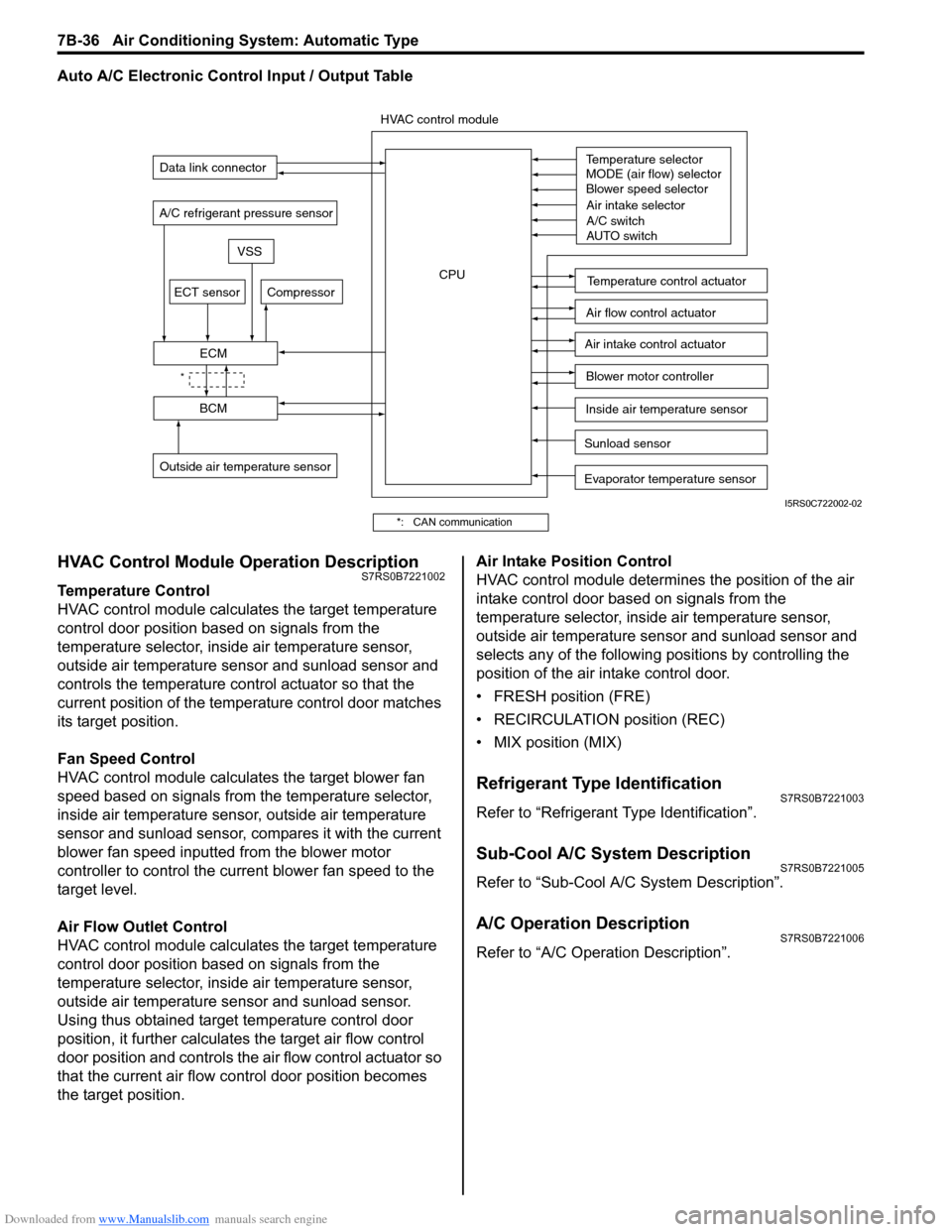
Auto A/C Electronic Control Input / Output Table
HVAC Control Module Operation DescriptionS7RS0B7221002
Temperature Control
HVAC control module calculates the target temperature
control door position based on signals from the
temperature selector, inside air temperature sensor,
outside air temperature sensor and sunload sensor and
controls the temperature control actuator so that the
current position of the temperature control door matches
its target position.
Fan Speed Control
HVAC control module calculates the target blower fan
speed based on signals from the temperature selector,
inside air temperature sensor, outside air temperature
sensor and sunload sensor, compares it with the current
blower fan speed inputted from the blower motor
controller to control the current blower fan speed to the
target level.
Air Flow Outlet Control
HVAC control module calculates the target temperature
control door position based on signals from the
temperature selector, inside air temperature sensor,
outside air temperature sensor and sunload sensor.
Using thus obtained target temperature control door
position, it further calculates the target air flow control
door position and controls the ai r flow control actuator so
that the current air flow c ontrol door position becomes
the target position. Air Intake Position Control
HVAC control module determines the position of the air
intake control door based on signals from the
temperature selector, inside air temperature sensor,
outside air temperature sensor and sunload sensor and
selects any of the following positions by controlling the
position of the air intake control door.
• FRESH position (FRE)
• RECIRCULATION position (REC)
• MIX position (MIX)
Refrigerant Type IdentificationS7RS0B7221003
Refer to “Refrigerant Type Identification”.
Sub-Cool A/C System DescriptionS7RS0B7221005
Refer to “Sub-Cool A/C System Description”.
A/C Operation DescriptionS7RS0B7221006
Refer to “A/C Operation Description”.
Sunload sensor
Outside air temperature sensor Evaporator temperature sensor
A/C refrigerant pressure sensor
Temperature selector
MODE (air flow) selector
Blower speed selector
Air intake selector
AUTO switch
A/C switch
Compressor
Blower motor controller
Temperature control actuator
Air flow control actuator
Air intake control actuator
BCM
ECM
Data link connector
HVAC control module
CPU
ECT sensor
Inside air temperature sensor
VSS
*
I5RS0C722002-02
*: CAN communication
Page 995 of 1496
Downloaded from www.Manualslib.com manuals search engine Air Conditioning System: Automatic Type 7B-47
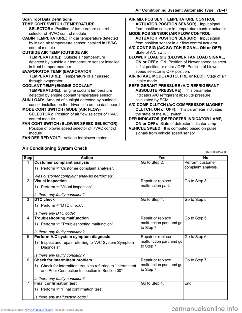
Scan Tool Data Definitions
TEMP CONT SWITCH (TEMPERATURE SELECTOR): Position of temperature control
selector of HVAC control module
CABIN TEMPERATURE: In-car temperature detected
by inside air temperature sensor installed in HVAC
control module
OUTSIDE AIR TEMP (OUTSIDE AIR TEMPERATURE): Outside air temperature
detected by outside air temperature sensor installed
in front bumper member
EVAPORATOR TEMP (EVAPORATOR TEMPERATURE): Temperature of air passed
through evaporator
COOLANT TEMP (ENGINE COOLANT TEMPERATURE): Engine coolant temperature
detected by engine coolant temperature sensor
SUN LOAD: Amount of sunlight detected by sunload
sensor installed on the driver side on the dashboard
MODE CONT SWITCH (MODE (AIR FLOW) SELECTOR): Position of air flow selector of HVAC
control module
FAN CONT SWITCH (BLOWER SPEED SELECTOR): Position of blower speed selector of HVAC control
module
FAN DESIRED VOLT: Voltage for blower motor AIR MIX POS SEN (TEMPERATURE CONTROL
ACTUATOR POSITI ON SENSOR): Input signal
from position sensor in temperature control actuator
MODE POS SENSOR (AIR FLOW CONTROL ACTUATOR POSITI ON SENSOR): Input signal
from position sensor in air flow control actuator
A/C CONT SIG (A/C SWITCH SIGNAL, ON or OFF): State of A/C switch
BLOWER LOAD SIG (BLO WER FAN LOAD SIGNAL,
ON or OFF): ON: Position of blower speed selector
is 1st position or more / OFF: Position of blower
speed selector is OFF position.
AIR INTAKE MODE (AUTO, FRE or REC): State of air
intake mode
REFRIGERANT PRESSURE (A/C REFRIGERANT ABSOLUTE PRESSURE): This parameter
indicates A/C refrigerant absolute pressure
calculated by ECM
A/C COMP CLUTCH (A/C COMPRESSOR MAGNET CLUTCH, ON or OFF): This parameter indicates
the state of the A/C switch
DFR INDICATOR (DEFROSTER INDICATOR LAMP, ON or OFF): State of defroster indicator lamp
VEHICLE SPEED: It is computed based on pulse
signals from vehicle speed sensor
Air Conditioning System CheckS7RS0B7224008
Step Action YesNo
1 Customer complaint analysis
1) Perform �)”Customer complaint analysis”.
Was customer complaint analysis performed? Go to Step 2.
Perform customer
complaint analysis.
2 Visual inspection
1) Perform �)“Visual inspection”.
Is there any faulty condition? Repair or replace
malfunction part.
Go to Step 3.
3 DTC check
1) Perform �)“DTC check”.
Is there any DTC code? Go to Step 4.
Go to Step 5.
4 Troubleshooting malfunction
1) Perform �) “Troubleshooting malfunction”.
Is there any faulty condition? Repair or replace
malfunction part, and go
to Step 7.
Go to Step 5.
5 Perform A/C system symptom diagnosis
1) Inspect and repair referri ng to “A/C System Symptom
Diagnosis”.
Is there any faulty condition? Repair or replace
malfunction part, and go
to Step 7.
Go to Step 6.
6 Check for intermittent problem
1) Check for intermittent troubles referring to “Intermittent
and Poor Connection Inspection in Section 00”.
Is there any faulty condition? Repair or replace
malfunction part, and go
to Step 7.
Go to Step 7.
7 Final confirmation test
1) Perform �) “Final confirmation test”.
Is there any malfunction code? Go to Step 4.
End.
Page 1296 of 1496
Downloaded from www.Manualslib.com manuals search engine 9C-1 Instrumentation / Driver Info. / Horn:
Body, Cab and Accessories
Instrumentation / Driver Info. / Horn
Precautions
Precautions in Diagnosing Troubles for Combination MeterS7RS0B9300001
Combination meter uses signals (information) from each control module by CAN communication to control
speedometer, tachometer, engine coolant temp meter, warning light and indicator light (other than air bag warning
light, high beam indicator light, EPS warn ing light and turn signal indicator light). Therefore, check that no DTC is
detected in each module before performing combination me ter symptom diagnosis. If any DTC is detected, correct
trouble indicated by that DTC troubleshooting first.
General Description
CAN Communication System DescriptionS7RS0B9301001
Refer to “CAN Communication System Description in Section 1A” for Can communication system description.
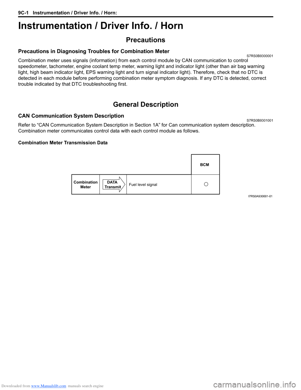
Combination meter communicates control data with each control module as follows.
Combination Meter Transmission Data
BCM
Combination Meter DATA
TransmitFuel level signal
I7RS0A930001-01
Page 1416 of 1496
Downloaded from www.Manualslib.com manuals search engine 10B-13 Body Electrical Control System:
Scan Tool Data Definitions
Vehicle Speed (km/h, mph): It is computed based on pulse signals from vehicle speed sensor on transmission.
Outside air Temp ( °C, °F): It is detected by outside air temperature sensor.
Battery Voltage (V): This parameter indicates battery po sitive voltage inputted to BCM.
Coolant Temp (Engine coolant temperature) ( °C, °F): It is detected by engine coolant temperature sensor.
Engine Speed (RPM): It is computed by reference pulse signals from CMP sensor.
Fuel Consumption (km/l): This parameter indicates the fuel consumption computed by ECM.
Key Reminder Sw (Key reminder switch) (Pulled / Key in): This parameter indicates the state of the key reminder
switch.
Rear Wiper Sw (Rear wiper switch) (ON / INT / OFF): This parameter indicates the state of the rear wiper switch.
Door key Sw (Door key cylinder switch) (Lock / Neutral / Unlock): This parameter indicates the state of the door
key cylinder switch.
Door lock Sw (Manual door lock switch) (Lock / Neutral / Unlock): This parameter indicates the state of the
manual door lock switch.
Driv Door Sw (Driver side d oor switch) (Open / Close): This parameter indicates the state of the driver side door
switch.
Pass Door Sw (Other than driver side door switch) (Open / Close): This parameter indicates the state of the door
switches other than driver side door switch.
Brake Fluid Level (Low / Normal): Low: Brake fluid level is lower than specified level.
Normal: Brake fluid level is higher than MIN level.
Parking Brake Sw (Parking brake switch) (ON / OFF): ON: Parking brake lever is pulled up.
OFF: Parking brake lever is released.
Rear Defogger Sw (Rear end door window defogger switch) (ON / OFF): This parameter indicates the state of
the rear end door window defogger switch.
Tail Light Sw (Lighting switch) (ON / OFF): This parameter indicates the state of the lighting switch.
Driv Seatbelt Sw (Driver seat belt switch) (Fasten / Unfasten): This parameter indicates the state of the driver
side seat belt buckle switch.
Rear end Door Opener (Rear end door opener switch) (ON / OFF): This parameter indicates the state of the rear
end door opener switch.
“3” position Sw (ON/OFF): This parameter indicates the state of the “3 ” position switch included in A/T manual
selector assembly.
Charge lamp (ON / OFF): This parameter indicates the state of the charge system monitor switch.
Oil pressure switch (ON / OFF): This parameter indicates the state of the oil pressure switch.
A/C Switch (ON / OFF): This parameter indicates the state of the air conditioning switch.
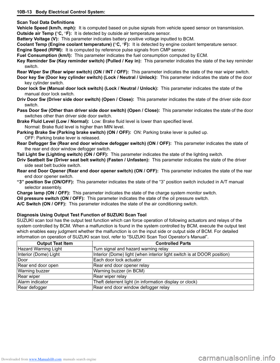
Diagnosis Using Output Test Function of SUZUKI Scan Tool
SUZUKI scan tool has the output test function which can force operation of following actuators and relays of the
system controlled by BCM. When a malf unction is found in the system controlled by BCM, execute the output test
which enables easy judgment whether the malfunction is on the input side or output side of BCM. For detailed
information on operation of SUZUKI scan tool, refer to “SUZUKI Scan Tool Operator’s Manual”.
Output Teat Item Controlled Parts
Hazard Warning Light Turn signal and hazard warning relay
Interior (Dome) Light Interior (Dome) light (wh en interior light switch is at DOOR position)
Door Each door lock actuator
Rear end door open Rear end door opener relay
Warning buzzer Warning buzzer (in BCM)
Rear wiper Rear wiper relay
Alarm indicator Theft deterrent light (in information display or clock)
Rear defogger Rear end door window defogger relay
Page 1474 of 1496
Downloaded from www.Manualslib.com manuals search engine 10E-12 Keyless Start System:
DTC ClearanceS7RS0BA504009
1) Perform Steps 1) through 5) of DTC check procedure and have DTC indicated.
2) Open driver side door.
3) Close driver side door and within 10 seconds after that, perform Steps a) to c) described below.
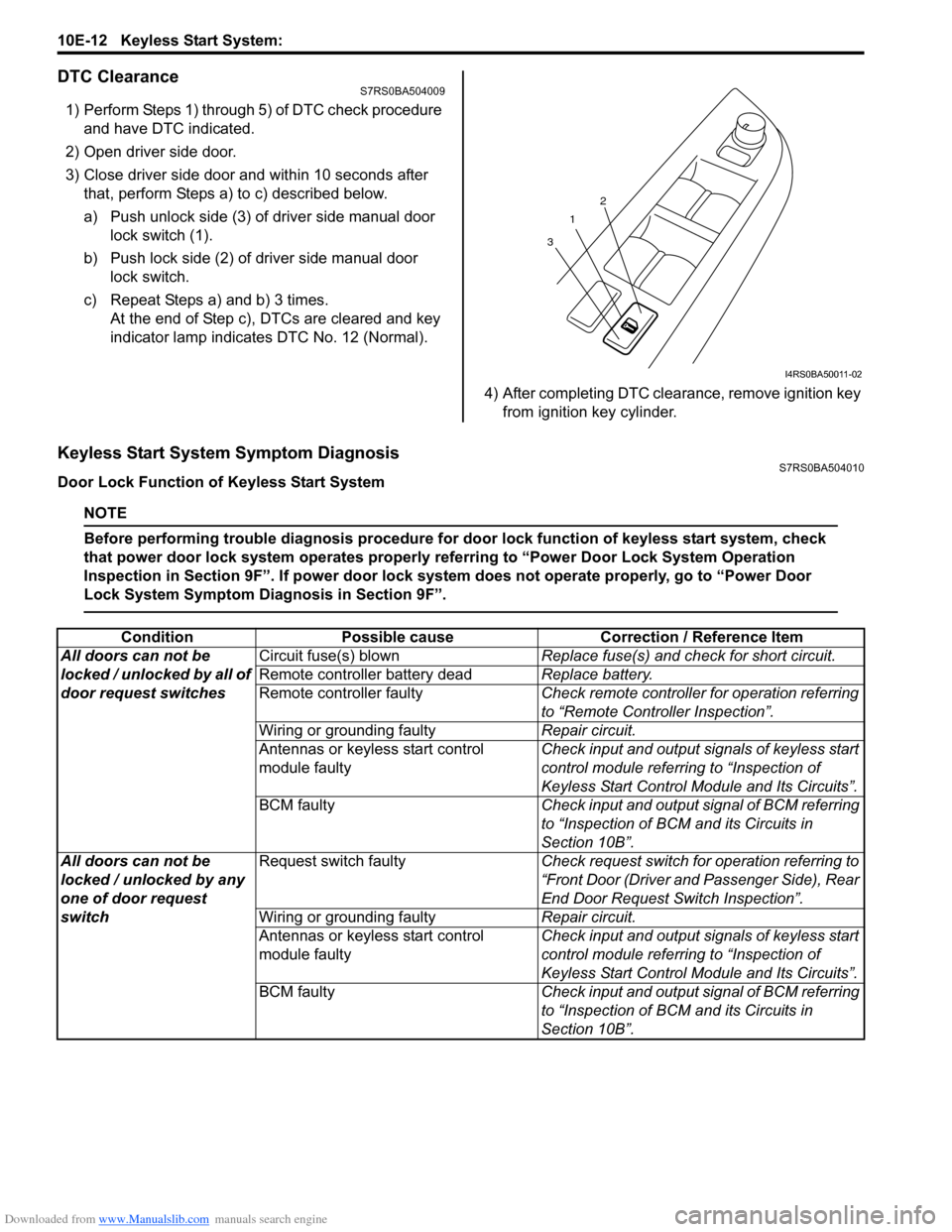
a) Push unlock side (3) of driver side manual door lock switch (1).
b) Push lock side (2) of driver side manual door lock switch.
c) Repeat Steps a) and b) 3 times. At the end of Step c), DTCs are cleared and key
indicator lamp indicates DTC No. 12 (Normal).
4) After completing DTC clearance, remove ignition key from ignition key cylinder.
Keyless Start System Symptom DiagnosisS7RS0BA504010
Door Lock Function of Keyless Start System
NOTE
Before performing trouble diagnosis procedure for door lock function of keyless start system, check
that power door lock system operates properly referring to “Power Door Lock System Operation
Inspection in Section 9F”. If power door lock system does not operate properly, go to “Power Door
Lock System Symptom Diagnosis in Section 9F”.
1
3 2
I4RS0BA50011-02
Condition
Possible cause Correction / Reference Item
All doors can not be
locked / unlocked by all of
door request switches Circuit fuse(s) blown
Replace fuse(s) and check for short circuit.
Remote controller battery dead Replace battery.
Remote controller faulty Check remote controller for operation referring
to “Remote Controller Inspection”.
Wiring or grounding faulty Repair circuit.
Antennas or keyless start control
module faulty Check input and output signals of keyless start
control module referring to “Inspection of
Keyless Start Control Mo
dule and Its Circuits”.
BCM faulty Check input and output signal of BCM referring
to “Inspection of BCM and its Circuits in
Section 10B”.
All doors can not be
locked / unlocked by any
one of door request
switch Request switch faulty
Check request switch for operation referring to
“Front Door (Driver and Passenger Side), Rear
End Door Request Switch Inspection”.
Wiring or grounding faulty Repair circuit.
Antennas or keyless start control
module faulty Check input and output signals of keyless start
control module referring to “Inspection of
Keyless Start Control Mo
dule and Its Circuits”.
BCM faulty Check input and output signal of BCM referring
to “Inspection of BCM and its Circuits in
Section 10B”.
Page 1475 of 1496
Downloaded from www.Manualslib.com manuals search engine Keyless Start System: 10E-13
Keyless Engine Start Function
NOTE
Before performing symptom diagnosis procedure for keyless engine start system, check that engine
starts by using ignition key. If it cannot be started by using ignition key, go to “Engine Symptom
Diagnosis in Section 1A”.
Keyless Start System Operation InspectionS7RS0BA504011
Keyless engine start operation
1) Sit in driver seat with re mote controller carried with
you.
2) Check that all doors are closed and ignition key is not inserted in ignition key cylinder.
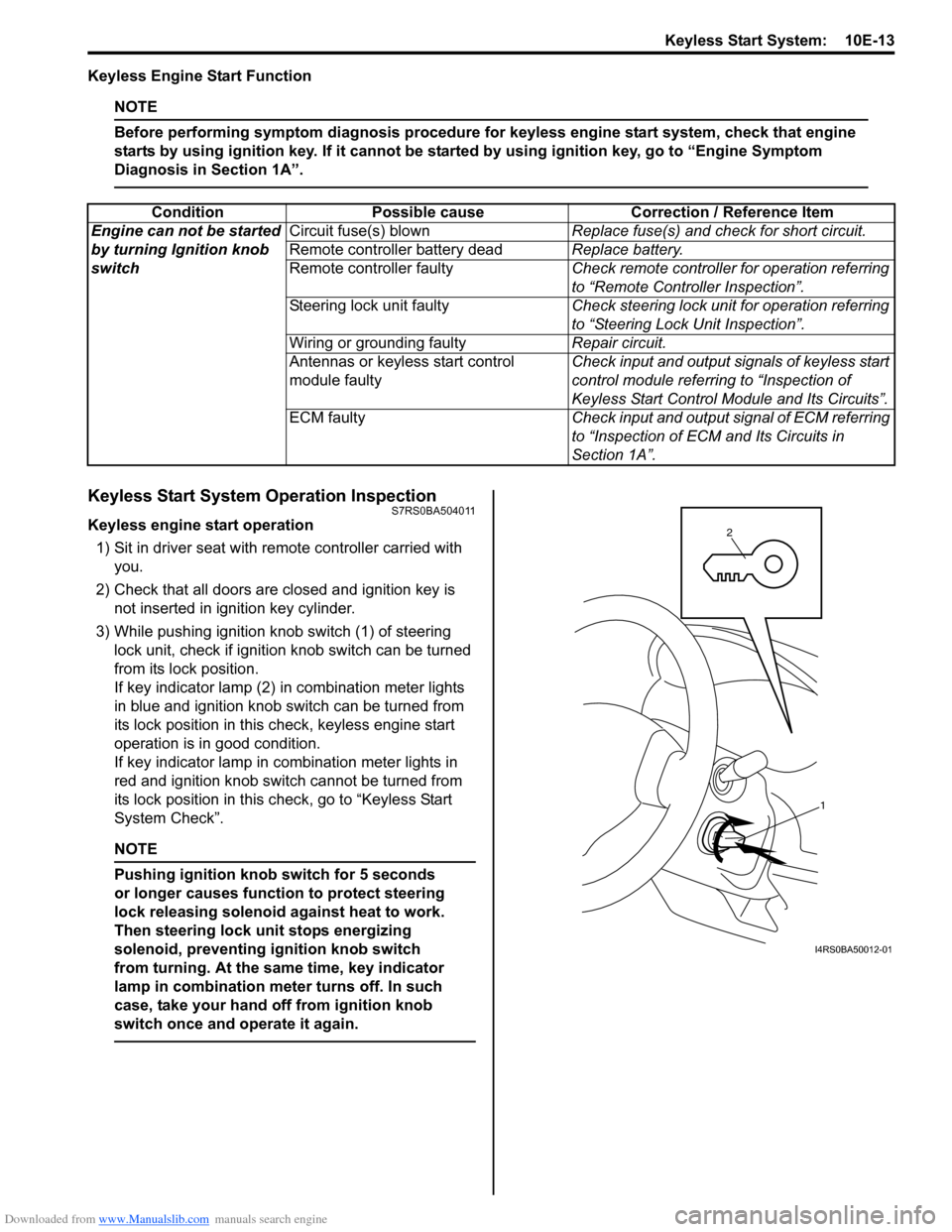
3) While pushing ignition knob switch (1) of steering lock unit, check if ignition knob switch can be turned
from its lock position.
If key indicator lamp (2) in combination meter lights
in blue and ignition knob switch can be turned from
its lock position in this check, keyless engine start
operation is in good condition.
If key indicator lamp in combination meter lights in
red and ignition knob switch cannot be turned from
its lock position in this check, go to “Keyless Start
System Check”.
NOTE
Pushing ignition knob switch for 5 seconds
or longer causes function to protect steering
lock releasing solenoid against heat to work.
Then steering lock unit stops energizing
solenoid, preventing ignition knob switch
from turning. At the same time, key indicator
lamp in combination mete r turns off. In such
case, take your hand off from ignition knob
switch once and operate it again.
Condition Possible cause Correction / Reference Item
Engine can not be started
by turning Ignition knob
switch Circuit fuse(s) blown
Replace fuse(s) and check for short circuit.
Remote controller battery dead Replace battery.
Remote controller faulty Check remote controller for operation referring
to “Remote Controller Inspection”.
Steering lock unit faulty Check steering lock unit for operation referring
to “Steering Lock Unit Inspection”.
Wiring or grounding faulty Repair circuit.
Antennas or keyless start control
module faulty Check input and output signals of keyless start
control module referring to “Inspection of
Keyless Start Control Mo
dule and Its Circuits”.
ECM faulty Check input and output signal of ECM referring
to “Inspection of ECM and Its Circuits in
Section 1A”.
1
2
I4RS0BA50012-01
Page 1478 of 1496
Downloaded from www.Manualslib.com manuals search engine 10E-16 Keyless Start System:
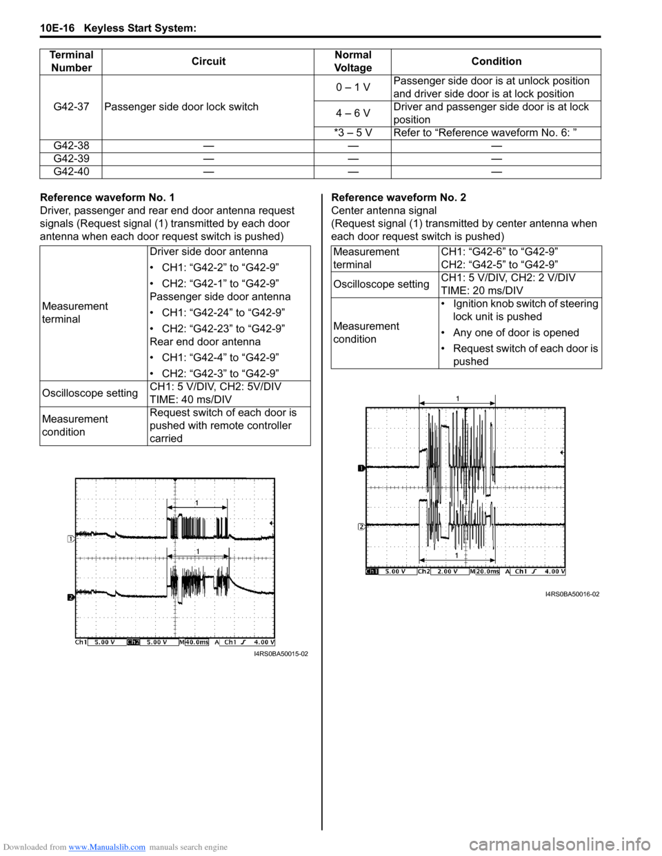
Reference waveform No. 1
Driver, passenger and rear end door antenna request
signals (Request signal (1) transmitted by each door
antenna when each door request switch is pushed)Reference waveform No. 2
Center antenna signal
(Request signal (1) transmitted by center antenna when
each door request switch is pushed)
G42-37 Passenger side door lock switch
0 – 1 V
Passenger side door is at unlock position
and driver side door is at lock position
4 – 6 V Driver and passenger side door is at lock
position
*3 – 5 V Refer to “Reference waveform No. 6: ”
G42-38 — — —
G42-39 — — —
G42-40 — — —
Terminal
Number Circuit Normal
Vo l ta g e Condition
Measurement
terminalDriver side door antenna
• CH1: “G42-2” to “G42-9”
• CH2: “G42-1” to “G42-9”
Passenger side door antenna
• CH1: “G42-24” to “G42-9”
• CH2: “G42-23” to “G42-9”
Rear end door antenna
• CH1: “G42-4” to “G42-9”
• CH2: “G42-3” to “G42-9”
Oscilloscope setting CH1: 5 V/DIV, CH2: 5V/DIV
TIME: 40 ms/DIV
Measurement
condition Request switch of each door is
pushed with remote controller
carried
I4RS0BA50015-02
Measurement
terminal
CH1: “G42-6” to “G42-9”
CH2: “G42-5” to “G42-9”
Oscilloscope setting CH1: 5 V/DIV, CH2: 2 V/DIV
TIME: 20 ms/DIV
Measurement
condition • Ignition knob switch of steering
lock unit is pushed
• Any one of door is opened
• Request switch of each door is pushed
I4RS0BA50016-02
Page 1479 of 1496
Downloaded from www.Manualslib.com manuals search engine Keyless Start System: 10E-17
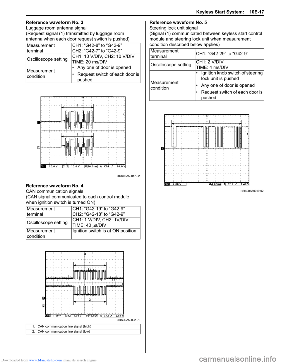
Reference waveform No. 3
Luggage room antenna signal
(Request signal (1) transmitted by luggage room
antenna when each door request switch is pushed)
Reference waveform No. 4
CAN communication signals
(CAN signal communicated to each control module
when ignition switch is turned ON)Reference waveform No. 5
Steering lock unit signal
(Signal (1) communicated between keyless start control
module and steering lock unit when measurement
condition described below applies)
Measurement
terminal CH1: “G42-8” to “G42-9”
CH2: “G42-7” to “G42-9”
Oscilloscope setting CH1: 10 V/DIV, CH2: 10 V/DIV
TIME: 20 ms/DIV
Measurement
condition • Any one of door is opened
• Request switch of each door is
pushed
Measurement
terminal CH1: “G42-19” to “G42-9”
CH2: “G42-18” to “G42-9”
Oscilloscope setting CH1: 1 V/DIV, CH2: 1V/DIV
TIME: 40
µs/DIV
Measurement
condition Ignition switch is at ON position
1. CAN communication line signal (high)
2. CAN communication line signal (low)
I4RS0BA50017-02
I5RS0DA50002-01
Measurement
terminal
CH1: “G42-29” to “G42-9”
Oscilloscope setting CH1: 2 V/DIV
TIME: 4 ms/DIV
Measurement
condition • Ignition knob switch of steering
lock unit is pushed
• Any one of door is opened
• Request switch of each door is pushed
I4RS0BA50019-02