2007 SUZUKI SWIFT Ket
[x] Cancel search: KetPage 670 of 1496
Downloaded from www.Manualslib.com manuals search engine 5A-26 Automatic Transmission/Transaxle:
TRANSAXLE RANGE
Transaxle range detected by signal fed from
transmission range sensor.
D RANGE SIGNAL
ON: Signal which TCM require ECM to increase idle
speed
OFF: Signal which TCM does not require ECM to
increase idle speed
THROTTLE POSITION (%)
Throttle opening ratio computed by CAN signal from
ECM.
BRAKE SWITCH
Inputted signal from brake light switch on pedal bracket.
ON: Brake pedal depressed
OFF: Brake pedal released
TORQUE REDUCTION SIGNAL
ON: Signal which TCM require ECM to reduce output
torque at shifting gear
OFF: Signal which TCM does not require ECM to reduce
output torque
ENGINE COOLANT TEMPERATURE ( °C, °F)
Engine coolant temperature computed by CAN signal
from ECM. AIR CONDITIONER SIGNAL
ON: Signal which inform that air conditioner compressor
is turned ON.
OFF: Signal which inform that air conditioner
compressor is not turned ON.
ENGINE TORQUE SIGNAL (N
⋅m)
Engine torque computed by duty pulse signal outputted
from ECM.
SLIP RPM (RPM)
This parameter indicates slip ping rotation in the torque
converter (difference between input shaft rotation and
engine rotation)
MIL REQUEST
ON: Signal which TCM requires combination meter to
turn on malfunction indicator lamp.
OFF: Signal which TCM does not require combination
meter to turn on malf unction indicator lamp.
FUEL CUT FLAG
ON: Signal which inform that fuel cut is operating.
OFF: Signal which inform that fuel cut is not operating.
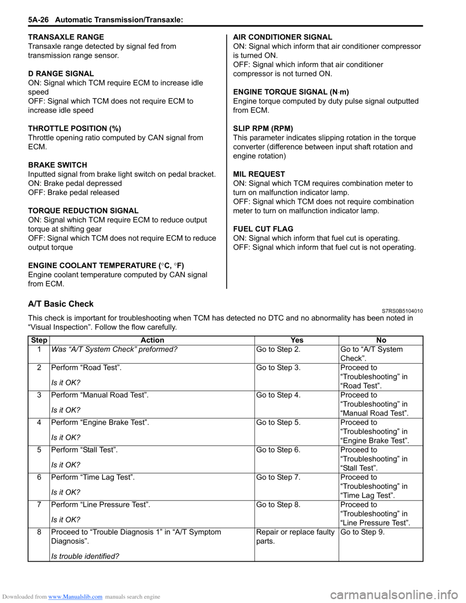
A/T Basic CheckS7RS0B5104010
This check is important for troubleshooting when TCM has detected no DTC and no abnormality has been noted in
“Visual Inspection”. Fo llow the flow carefully.
Step Action YesNo
1 Was “A/T System Check” preformed? Go to Step 2.Go to “A/T System
Check”.
2 Perform “Road Test”.
Is it OK? Go to Step 3.
Proceed to
“Troubleshooting” in
“Road Test”.
3 Perform “Manual Road Test”.
Is it OK? Go to Step 4.
Proceed to
“Troubleshooting” in
“Manual Road Test”.
4 Perform “Engine Brake Test”.
Is it OK? Go to Step 5.
Proceed to
“Troubleshooting” in
“Engine Brake Test”.
5 Perform “Stall Test”.
Is it OK? Go to Step 6.
Proceed to
“Troubleshooting” in
“Stall Test”.
6 Perform “Time Lag Test”.
Is it OK? Go to Step 7.
Proceed to
“Troubleshooting” in
“Time Lag Test”.
7 Perform “Line Pressure Test”.
Is it OK? Go to Step 8.
Proceed to
“Troubleshooting” in
“Line Pressure Test”.
8 Proceed to “Trouble Diag nosis 1” in “A/T Symptom
Diagnosis”.
Is trouble identified? Repair or replace faulty
parts.
Go to Step 9.
Page 736 of 1496
Downloaded from www.Manualslib.com manuals search engine 5A-92 Automatic Transmission/Transaxle:
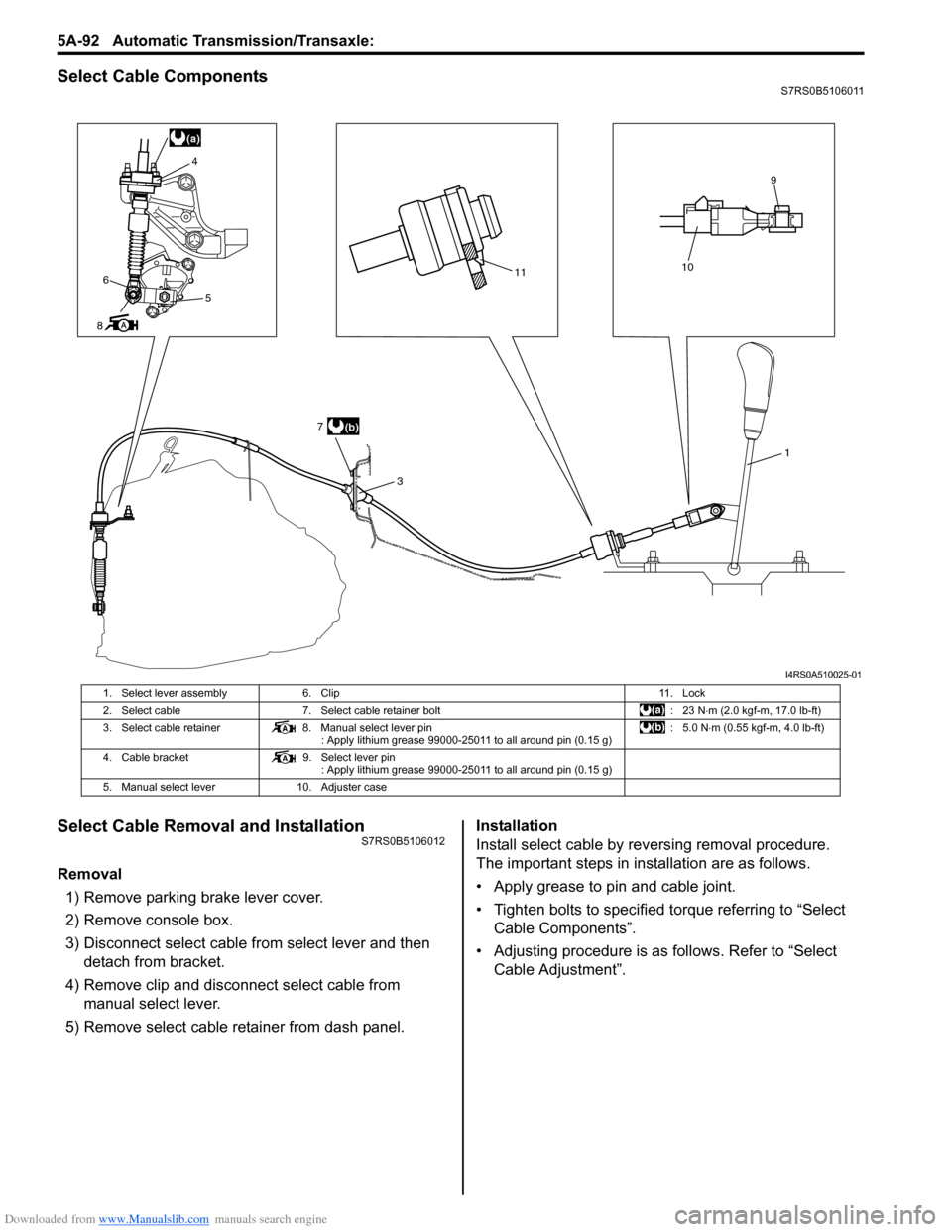
Select Cable ComponentsS7RS0B5106011
Select Cable Removal and InstallationS7RS0B5106012
Removal
1) Remove parking brake lever cover.
2) Remove console box.
3) Disconnect select cable from select lever and then detach from bracket.
4) Remove clip and disconnect select cable from manual select lever.
5) Remove select cable retainer from dash panel. Installation
Install select cable by reversing removal procedure.
The important steps in inst
allation are as follows.
• Apply grease to pin and cable joint.
• Tighten bolts to specified torque referring to “Select Cable Components”.
• Adjusting procedure is as follows. Refer to “Select Cable Adjustment”.
(a)
11
3
10
9
6
8 4
5
(b)
7
1
I4RS0A510025-01
1. Select lever assembly
6. Clip 11. Lock
2. Select cable 7. Select cable retainer bolt : 23 N⋅m (2.0 kgf-m, 17.0 lb-ft)
3. Select cable retainer 8. Manual select lever pin
: Apply lithium grease 99000-25011 to all around pin (0.15 g) :5.0 N
⋅m (0.55 kgf-m, 4.0 lb-ft)
4. Cable bracket 9. Select lever pin
: Apply lithium grease 99000-25011 to all around pin (0.15 g)
5. Manual select lever 10. Adjuster case
Page 738 of 1496
Downloaded from www.Manualslib.com manuals search engine 5A-94 Automatic Transmission/Transaxle:
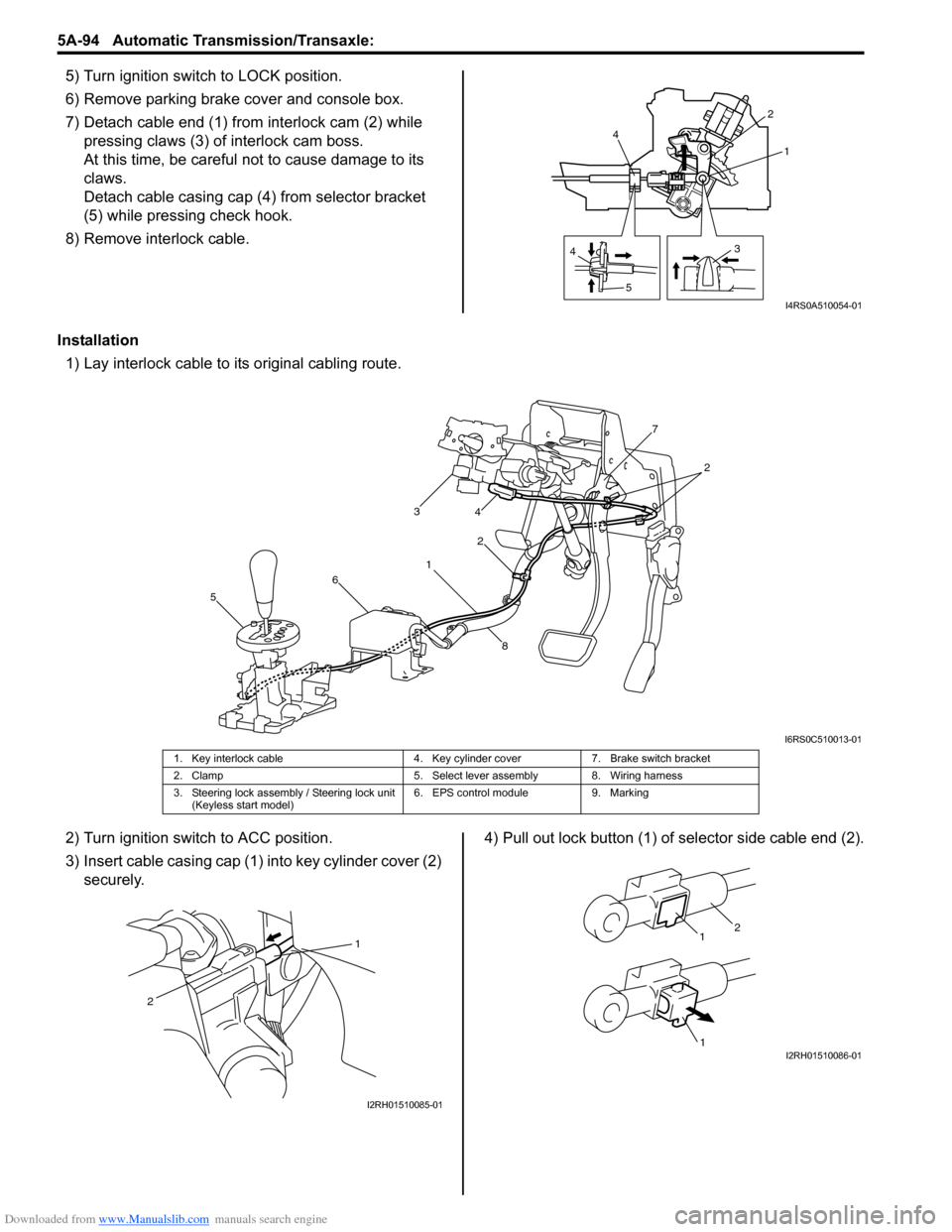
5) Turn ignition switch to LOCK position.
6) Remove parking brake cover and console box.
7) Detach cable end (1) from interlock cam (2) while
pressing claws (3) of interlock cam boss.
At this time, be careful no t to cause damage to its
claws.
Detach cable casing cap (4 ) from selector bracket
(5) while pressing check hook.
8) Remove interlock cable.
Installation 1) Lay interlock cable to its original cabling route.
2) Turn ignition switch to ACC position.
3) Insert cable casing cap (1) into key cylinder cover (2) securely. 4) Pull out lock button (1) of selector side cable end (2).
4
5 31
2
4
I4RS0A510054-01
1 2
3
4
5 6 7
8
2
I6RS0C510013-01
1. Key interlock cable 4. Key cylinder cover7. Brake switch bracket
2. Clamp 5. Select lever assembly 8. Wiring harness
3. Steering lock assembly / Steering lock unit (Keyless start model) 6. EPS control module
9. Marking
1
2
I2RH01510085-01
1
1
2
I2RH01510086-01
Page 739 of 1496
Downloaded from www.Manualslib.com manuals search engine Automatic Transmission/Transaxle: 5A-95
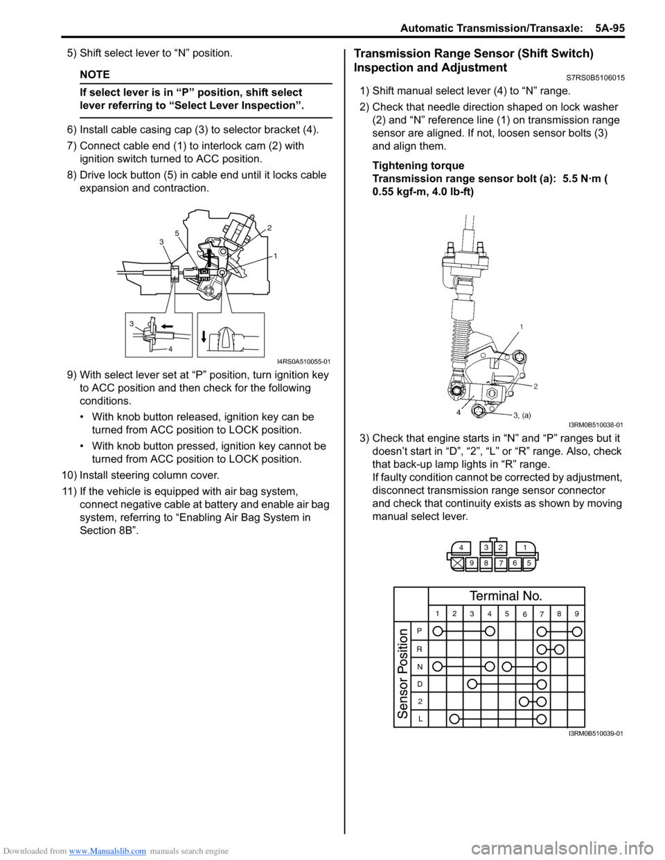
5) Shift select lever to “N” position.
NOTE
If select lever is in “P” position, shift select
lever referring to “Select Lever Inspection”.
6) Install cable casing cap (3) to selector bracket (4).
7) Connect cable end (1) to interlock cam (2) with ignition switch turned to ACC position.
8) Drive lock button (5) in cable end until it locks cable expansion and contraction.
9) With select lever set at “P ” position, turn ignition key
to ACC position and then check for the following
conditions.
• With knob button released, ignition key can be turned from ACC position to LOCK position.
• With knob button pressed, ignition key cannot be
turned from ACC position to LOCK position.
10) Install steering column cover. 11) If the vehicle is equipped with air bag system, connect negative cable at battery and enable air bag
system, referring to “Enabling Air Bag System in
Section 8B”.
Transmission Range Sensor (Shift Switch)
Inspection and Adjustment
S7RS0B5106015
1) Shift manual select lever (4) to “N” range.
2) Check that needle direction shaped on lock washer (2) and “N” reference line (1) on transmission range
sensor are aligned. If not, loosen sensor bolts (3)
and align them.
Tightening torque
Transmission range sensor bolt (a): 5.5 N·m (
0.55 kgf-m, 4.0 lb-ft)
3) Check that engine starts in “N” and “P” ranges but it doesn’t start in “D”, “2”, “L” or “R” range. Also, check
that back-up lamp lights in “R” range.
If faulty condition cannot be corrected by adjustment,
disconnect transmission range sensor connector
and check that continuity ex ists as shown by moving
manual select lever.
3
4 1
2
3 5
I4RS0A510055-01
I3RM0B510038-01
4
3
2
1
98 76 5
12 345
6789
P
R N
D 2
L
I3RM0B510039-01
Page 741 of 1496
Downloaded from www.Manualslib.com manuals search engine Automatic Transmission/Transaxle: 5A-97
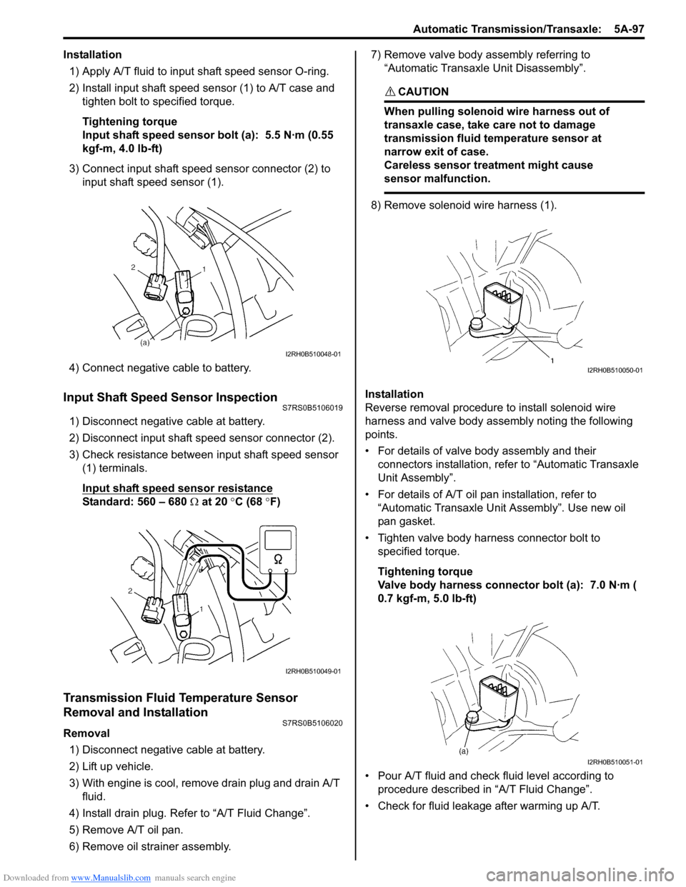
Installation1) Apply A/T fluid to input shaft speed sensor O-ring.
2) Install input shaft speed se nsor (1) to A/T case and
tighten bolt to specified torque.
Tightening torque
Input shaft speed sensor bolt (a): 5.5 N·m (0.55
kgf-m, 4.0 lb-ft)
3) Connect input shaft speed sensor connector (2) to input shaft speed sensor (1).
4) Connect negative cable to battery.
Input Shaft Speed Sensor InspectionS7RS0B5106019
1) Disconnect negative cable at battery.
2) Disconnect input shaft speed sensor connector (2).
3) Check resistance between input shaft speed sensor (1) terminals.
Input shaft speed sensor resistance
Standard: 560 – 680 Ω at 20 °C (68 °F)
Transmission Fluid Temperature Sensor
Removal and Installation
S7RS0B5106020
Removal
1) Disconnect negative cable at battery.
2) Lift up vehicle.
3) With engine is cool, remove drain plug and drain A/T fluid.
4) Install drain plug. Refer to “A/T Fluid Change”.
5) Remove A/T oil pan.
6) Remove oil stra iner assembly. 7) Remove valve body assembly referring to
“Automatic Transaxl e Unit Disassembly”.
CAUTION!
When pulling solenoid wire harness out of
transaxle case, take care not to damage
transmission fluid temperature sensor at
narrow exit of case.
Careless sensor treatment might cause
sensor malfunction.
8) Remove solenoid wire harness (1).
Installation
Reverse removal procedure to install solenoid wire
harness and valve body assembly noting the following
points.
• For details of valve body assembly and their connectors installation, refer to “Automatic Transaxle
Unit Assembly”.
• For details of A/T oil pa n installation, refer to
“Automatic Transaxle Unit Assembly”. Use new oil
pan gasket.
• Tighten valve body harness connector bolt to specified torque.
Tightening torque
Valve body harness connector bolt (a): 7.0 N·m (
0.7 kgf-m, 5.0 lb-ft)
• Pour A/T fluid and check fluid level according to procedure described in “A/T Fluid Change”.
• Check for fluid leakage after warming up A/T.
I2RH0B510048-01
I2RH0B510049-01
I2RH0B510050-01
I2RH0B510051-01
Page 742 of 1496
Downloaded from www.Manualslib.com manuals search engine 5A-98 Automatic Transmission/Transaxle:
Transmission Fluid Temperature Sensor
Inspection
S7RS0B5106021
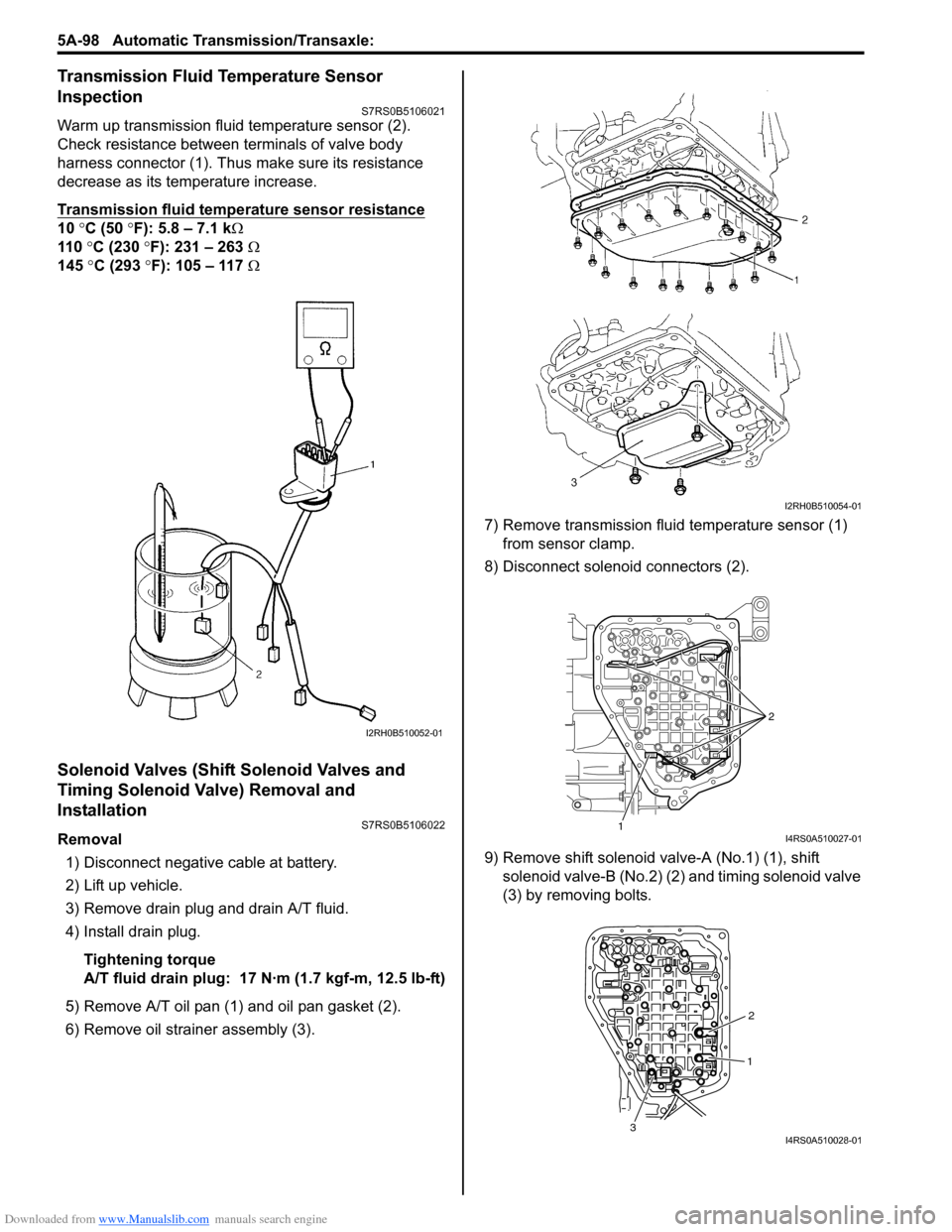
Warm up transmission fluid temperature sensor (2).
Check resistance between terminals of valve body
harness connector (1). Thus make sure its resistance
decrease as its temperature increase.
Transmission fluid temperature sensor resistance
10 °C (50 °F): 5.8 – 7.1 k Ω
110 °C (230 °F): 231 – 263 Ω
145 °C (293 °F): 105 – 117 Ω
Solenoid Valves (Shift Solenoid Valves and
Timing Solenoid Valve) Removal and
Installation
S7RS0B5106022
Removal
1) Disconnect negative cable at battery.
2) Lift up vehicle.
3) Remove drain plug and drain A/T fluid.
4) Install drain plug.
Tightening torque
A/T fluid drain plug: 17 N· m (1.7 kgf-m, 12.5 lb-ft)
5) Remove A/T oil pan (1) and oil pan gasket (2).
6) Remove oil strain er assembly (3). 7) Remove transmission fluid temperature sensor (1)
from sensor clamp.
8) Disconnect solenoid connectors (2).
9) Remove shift solenoid va lve-A (No.1) (1), shift
solenoid valve-B (No.2) (2) and timing solenoid valve
(3) by removing bolts.
I2RH0B510052-01
I2RH0B510054-01
1 2I4RS0A510027-01
1
2
3
I4RS0A510028-01
Page 743 of 1496
Downloaded from www.Manualslib.com manuals search engine Automatic Transmission/Transaxle: 5A-99
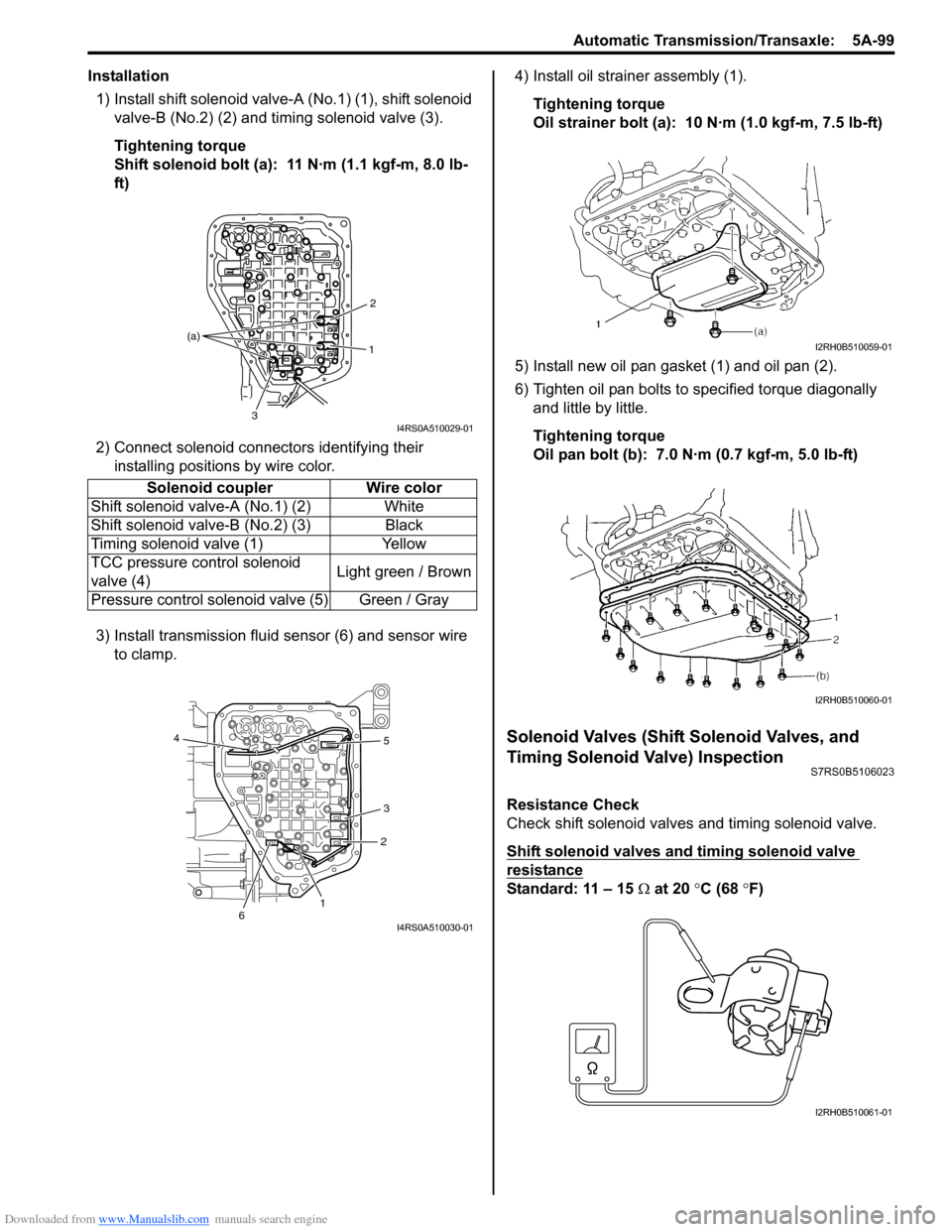
Installation1) Install shift solenoid valve- A (No.1) (1), shift solenoid
valve-B (No.2) (2) and timing solenoid valve (3).
Tightening torque
Shift solenoid bolt (a): 11 N·m (1.1 kgf-m, 8.0 lb-
ft)
2) Connect solenoid connectors identifying their installing positions by wire color.
3) Install transmission fluid sensor (6) and sensor wire to clamp. 4) Install oil strain
er assembly (1).
Tightening torque
Oil strainer bolt (a): 10 N·m (1.0 kgf-m, 7.5 lb-ft)
5) Install new oil pan gasket (1) and oil pan (2).
6) Tighten oil pan bolts to specified torque diagonally and little by little.
Tightening torque
Oil pan bolt (b): 7.0 N·m (0.7 kgf-m, 5.0 lb-ft)
Solenoid Valves (Shift Solenoid Valves, and
Timing Solenoid Valve) Inspection
S7RS0B5106023
Resistance Check
Check shift solenoid valves and timing solenoid valve.
Shift solenoid valves and timing solenoid valve
resistance
Standard: 11 – 15 Ω at 20 °C (68 ° F)
Solenoid coupler Wire color
Shift solenoid valv e-A (No.1) (2) White
Shift solenoid valv e-B (No.2) (3) Black
Timing solenoid valve (1) Yellow
TCC pressure control solenoid
valve (4) Light green / Brown
Pressure control solenoid valve (5) Green / Gray
1 2
3
(a)
I4RS0A510029-01
1
2
3 5
4
6
I4RS0A510030-01
I2RH0B510059-01
I2RH0B510060-01
I2RH0B510061-01
Page 745 of 1496
Downloaded from www.Manualslib.com manuals search engine Automatic Transmission/Transaxle: 5A-101
Pressure Control Solenoid Valves (Pressure
Control Solenoid and TCC Pressure Control
Solenoid) Removal and Installation
S7RS0B5106024
Removal1) Disconnect negative cable at battery.
2) Lift up vehicle.
3) Remove drain plug and drain A/T fluid.
4) Install drain plug.
Tightening torque
A/T fluid drain plug: 17 N·m (1.7 kgf-m, 12.5 lb-ft)
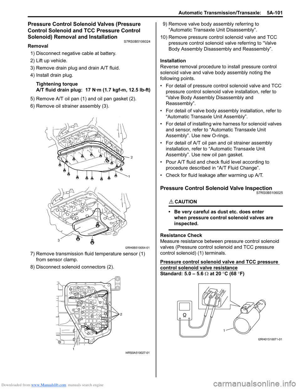
5) Remove A/T oil pan (1) and oil pan gasket (2).
6) Remove oil strain er assembly (3).
7) Remove transmission fluid temperature sensor (1) from sensor clamp.
8) Disconnect solenoid connectors (2). 9) Remove valve body assembly referring to
“Automatic Transaxl e Unit Disassembly”.
10) Remove pressure control solenoid valve and TCC pressure control solenoid valve referring to “Valve
Body Assembly Disassembly and Reassembly”.
Installation
Reverse removal procedure to install pressure control
solenoid valve and valve body assembly noting the
following points.
• For detail of pressure control solenoid valve and TCC pressure control solenoid va lve installation, refer to
“Valve Body Assembly Disassembly and
Reassembly”.
• For detail of valve body asse mbly installation, refer to
“Automatic Transaxle Unit Assembly”.
• For detail of installing wire harness for solenoid valves and sensor, refer to “Automatic Transaxle Unit
Assembly”. Use new O-rings.
• For detail of A/T oil pan and oil strainer assembly
installation, refer to “A utomatic Transaxle Unit
Assembly”. Use new oil pan gasket.
• Pour A/T fluid and check fluid level according to procedure described in “A/T Fluid Change”.
• Check for fluid leakage after warming up A/T.
Pressure Control Solenoid Valve InspectionS7RS0B5106025
CAUTION!
• Be very careful as dust etc. does enter when pressure control solenoid valves are
inspected.
Resistance Check
Measure resistance between pressure control solenoid
valves (Pressure control solenoid and TCC pressure
control solenoid) (1) terminals.
Pressure control solenoid valve and TCC pressure
control solenoid valve resistance
Standard: 5.0 – 5.6 Ω at 20 °C (68 °F)
I2RH0B510054-01
1 2I4RS0A510027-01
1
I2RH01510071-01