2007 SUZUKI SWIFT Ket
[x] Cancel search: KetPage 794 of 1496
Downloaded from www.Manualslib.com manuals search engine 5A-150 Automatic Transmission/Transaxle:
Automatic Transaxle Unit AssemblyS7RS0B5106060
CAUTION!
• Automatic transaxle consists of highly precise parts. As even flaw in small part
may cause oil leakage or decrease in
function, check each part carefully before
installation.
• Clean all parts with compressed air. Never use wiping cloths or rags.
• Before assembling new clutch or brake discs, soak them in automatic transaxle
fluid for at least 2 hours.
• Be sure to use new gaskets and O-rings.
• Lubricate O-rings with automatic transaxle
fluid.
• Apply automatic transaxle fluid on sliding or rotating surfaces of the parts before
assembly.
• Use Suzuki Super Grease “C” to retain parts in place.
• Be sure to install thrust bearings and races in correct direction and position.
• Make sure that snap ring ends are not aligned with one of cut outs and are
installed in groove correctly.
• Do not use adhesive cements on gaskets and similar parts.
• Be sure to torque each bolt and nut to specification.
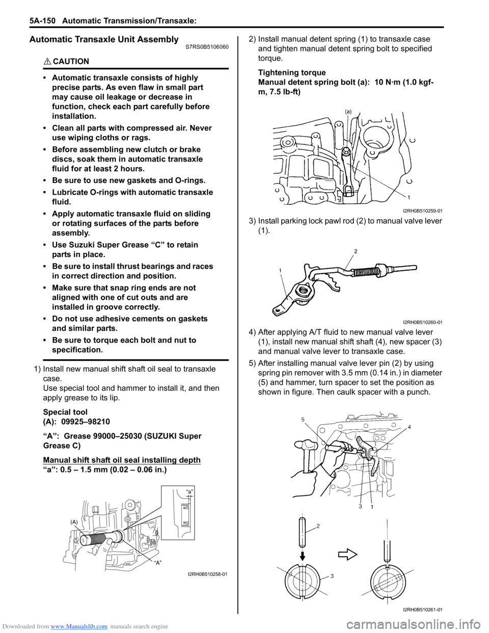
1) Install new manual shift sh aft oil seal to transaxle
case.
Use special tool and hammer to install it, and then
apply grease to its lip.
Special tool
(A): 09925–98210
“A”: Grease 99000–25030 (SUZUKI Super
Grease C)
Manual shift shaft oil seal installing depth
“a”: 0.5 – 1.5 mm (0.02 – 0.06 in.) 2) Install manual detent spring (1) to transaxle case
and tighten manual detent spring bolt to specified
torque.
Tightening torque
Manual detent spring bolt (a): 10 N·m (1.0 kgf-
m, 7.5 lb-ft)
3) Install parking lock pawl ro d (2) to manual valve lever
(1).
4) After applying A/T fluid to new manual valve lever (1), install new manual shift shaft (4), new spacer (3)
and manual valve lever to transaxle case.
5) After installing manual valve lever pin (2) by using spring pin remover with 3.5 mm (0.14 in.) in diameter
(5) and hammer, turn spacer to set the position as
shown in figure. Then caulk spacer with a punch.
“a”
(A)
“A”
I2RH0B510258-01
I2RH0B510259-01
I2RH0B510260-01
I2RH0B510261-01
Page 795 of 1496

Downloaded from www.Manualslib.com manuals search engine Automatic Transmission/Transaxle: 5A-151
6) Install parking lock pawl bracket (1) to transaxle
case.
Tightening torque
Parking lock pawl bracket bolt (a): 7.5 N·m (0.75
kgf-m, 5.5 lb-ft)
7) After applying A/T fluid to new O-rings, install them to 1st and reverse brake piston (3).
8) Install 1st and reverse brake piston (1) to transaxle case (2).
NOTE
Be careful not to damage O-ring when
installing 1st and reverse brake piston.
9) Install 1st and reverse brake return spring subassembly (1) to transaxle case (2).
10) Apply A/T fluid to 1st and reverse brake discs (2), separator plates (3) and retaining plate (1), then
install them to transaxle case.
11) Compress 1st and reverse brake return spring using special tool and hydraulic press, then attach snap
ring.
CAUTION!
Do not damage 1st and reverse brake return
spring subassembly discs, plates and piston
by pressing in 1st and reverse brake return
spring subassembly passing through its
original installing position over 0.8 mm (0.031
in.).
Special tool
(A): 09926–97620
1. Inner O-ring 2. Outer O-ring
I2RH0B510262-01
I2RH0B510263-01
I2RH0B510264-01
I2RH0B510265-01
I2RH0B510266-01
I2RH0B510267-01
Page 798 of 1496

Downloaded from www.Manualslib.com manuals search engine 5A-154 Automatic Transmission/Transaxle:
20) Check for correct installation of planetary gear assembly as follows.
Measure the distance “a” by using micrometer
caliper (1) and straightedge (2). If measured value is
out of specification, remove planetary gear assembly
and reinstall it properly.
Distance between planetary gear assembly and
mating surface of transaxle case
“a”: More than 49.9 m (1.965 in.)
21) Apply A/T fluid to one-way clutch No.2 assembly (1), then install it to planetar y gear assembly. After that,
ensure that planetary carrier rotates only in
counterclockwise direction “A”, not in clockwise
direction “B”. 22) Install one-way clutch outer race retainer (1).
23) Apply A/T fluid to new brake drum gasket (1), then
install it to transaxle case.
24) Apply A/T fluid to 2nd brak e retaining plate (1), discs
(2) and separator plates (3), then install them to
transaxle case.
25) Install 2nd brake return spring subassembly (1) to transaxle case.
“a”
“a”
2 1
I2RH0B510276-01
I2RH0B510277-01
I2RH0B510278-01
I2RH0B510279-01
2
3
1
I2RH0B510280-01
1
I2RH0B510281-01
Page 802 of 1496
Downloaded from www.Manualslib.com manuals search engine 5A-158 Automatic Transmission/Transaxle:
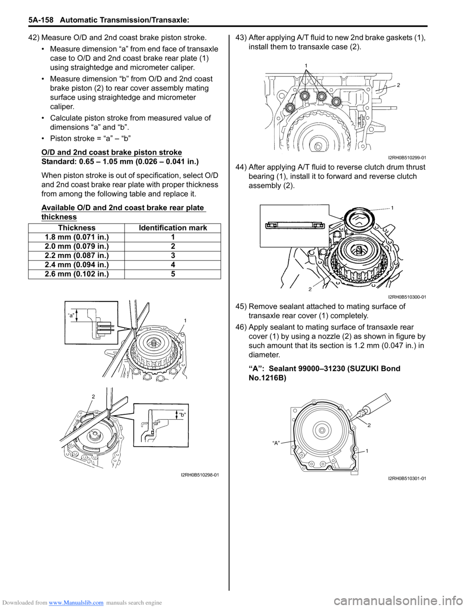
42) Measure O/D and 2nd coast brake piston stroke.• Measure dimension “a” from end face of transaxle case to O/D and 2nd coast brake rear plate (1)
using straightedge and micrometer caliper.
• Measure dimension “b” from O/D and 2nd coast brake piston (2) to rear cover assembly mating
surface using straightedge and micrometer
caliper.
• Calculate piston stroke from measured value of dimensions “a” and “b”.
• Piston stroke = “a” – “b”
O/D and 2nd coast brake piston stroke
Standard: 0.65 – 1.05 mm (0.026 – 0.041 in.)
When piston stroke is out of specification, select O/D
and 2nd coast brake rear plate with proper thickness
from among the following table and replace it.
Available O/D and 2nd coast brake rear plate
thickness
43) After applying A/T fluid to new 2nd brake gaskets (1), install them to transaxle case (2).
44) After applying A/T fluid to reverse clutch drum thrust bearing (1), install it to forward and reverse clutch
assembly (2).
45) Remove sealant attached to mating surface of transaxle rear cover (1) completely.
46) Apply sealant to mating surface of transaxle rear cover (1) by using a nozzle (2) as shown in figure by
such amount that its section is 1.2 mm (0.047 in.) in
diameter.
“A”: Sealant 99000–31230 (SUZUKI Bond
No.1216B)
Thickness Identification mark
1.8 mm (0.071 in.) 1
2.0 mm (0.079 in.) 2
2.2 mm (0.087 in.) 3
2.4 mm (0.094 in.) 4
2.6 mm (0.102 in.) 5
I2RH0B510298-01
I2RH0B510299-01
I2RH0B510300-01
“A” 2
1
I2RH0B510301-01
Page 803 of 1496
Downloaded from www.Manualslib.com manuals search engine Automatic Transmission/Transaxle: 5A-159
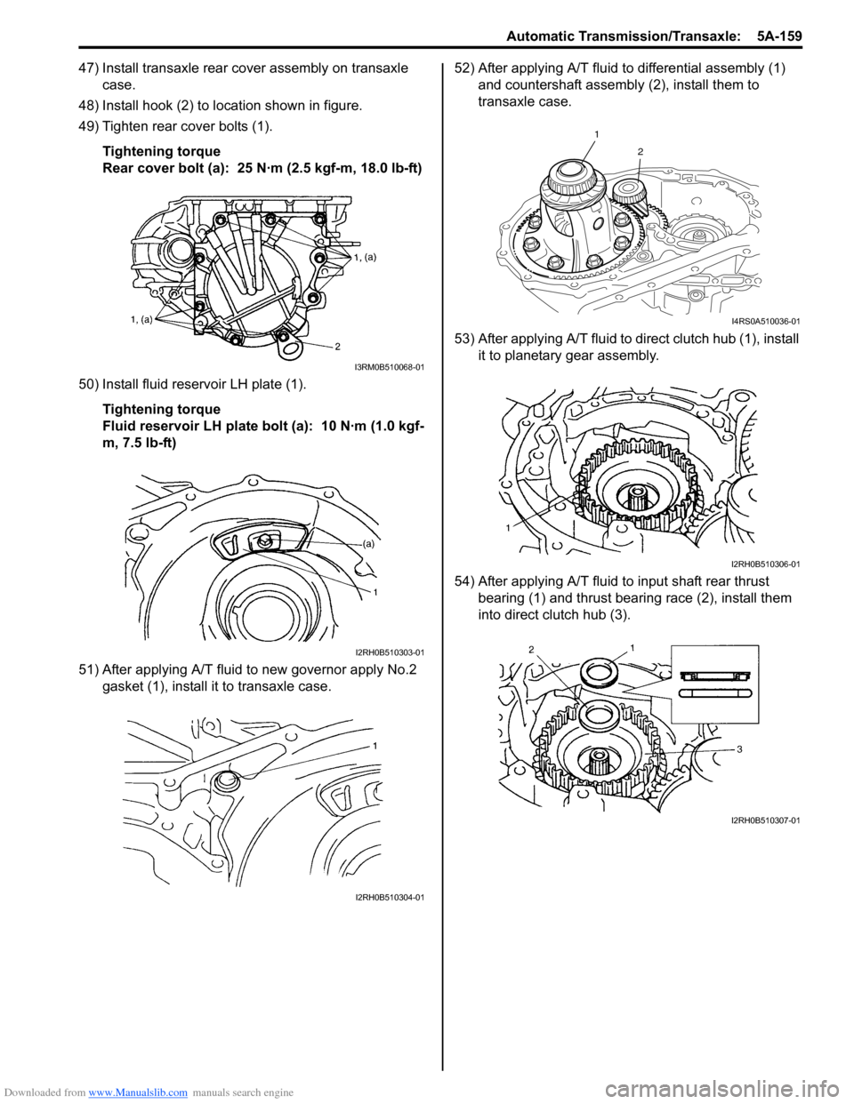
47) Install transaxle rear cover assembly on transaxle case.
48) Install hook (2) to location shown in figure.
49) Tighten rear cover bolts (1).
Tightening torque
Rear cover bolt (a): 25 N·m (2.5 kgf-m, 18.0 lb-ft)
50) Install fluid reservoir LH plate (1). Tightening torque
Fluid reservoir LH plate bolt (a): 10 N·m (1.0 kgf-
m, 7.5 lb-ft)
51) After applying A/T fluid to new governor apply No.2 gasket (1), install it to transaxle case. 52) After applying A/T fluid to differential assembly (1)
and countershaft assembly (2), install them to
transaxle case.
53) After applying A/T fluid to di rect clutch hub (1), install
it to planetary gear assembly.
54) After applying A/T fluid to input shaft rear thrust
bearing (1) and thrust bearing race (2), install them
into direct clutch hub (3).
I3RM0B510068-01
I2RH0B510303-01
I2RH0B510304-01
1
2
I4RS0A510036-01
I2RH0B510306-01
I2RH0B510307-01
Page 807 of 1496
Downloaded from www.Manualslib.com manuals search engine Automatic Transmission/Transaxle: 5A-163
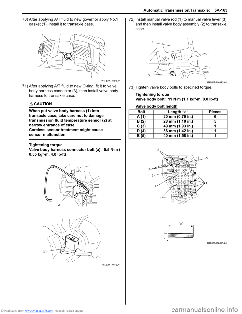
70) After applying A/T fluid to new governor apply No.1 gasket (1), install it to transaxle case.
71) After applying A/T fluid to new O-ring, fit it to valve body harness connector (3), then install valve body
harness to transaxle case.
CAUTION!
When put valve body harness (1) into
transaxle case, take care not to damage
transmission fluid temperature sensor (2) at
narrow entrance of case.
Careless sensor treatment might cause
sensor malfunction.
Tightening torque
Valve body harness connector bolt (a): 5.5 N·m (
0.55 kgf-m, 4.0 lb-ft) 72) Install manual valve rod (1) to manual valve lever (3)
and then install valve body assembly (2) to transaxle
case.
73) Tighten valve body bolts to specified torque. Tightening torque
Valve body bolt: 11 N·m (1.1 kgf-m, 8.0 lb-ft)
Valve body bolt length
I2RH0B510320-01
I2RH0B510321-01
Bolt Length “a” Pieces
A (1) 20 mm (0.79 in.) 6
B (2) 28 mm (1.10 in.) 5
C (3) 49 mm (1.93 in.) 1
D (4) 36 mm (1.42 in.) 1
E (5) 40 mm (1.58 in.) 1
I2RH0B510322-01
I2RH0B510323-01
Page 808 of 1496
Downloaded from www.Manualslib.com manuals search engine 5A-164 Automatic Transmission/Transaxle:
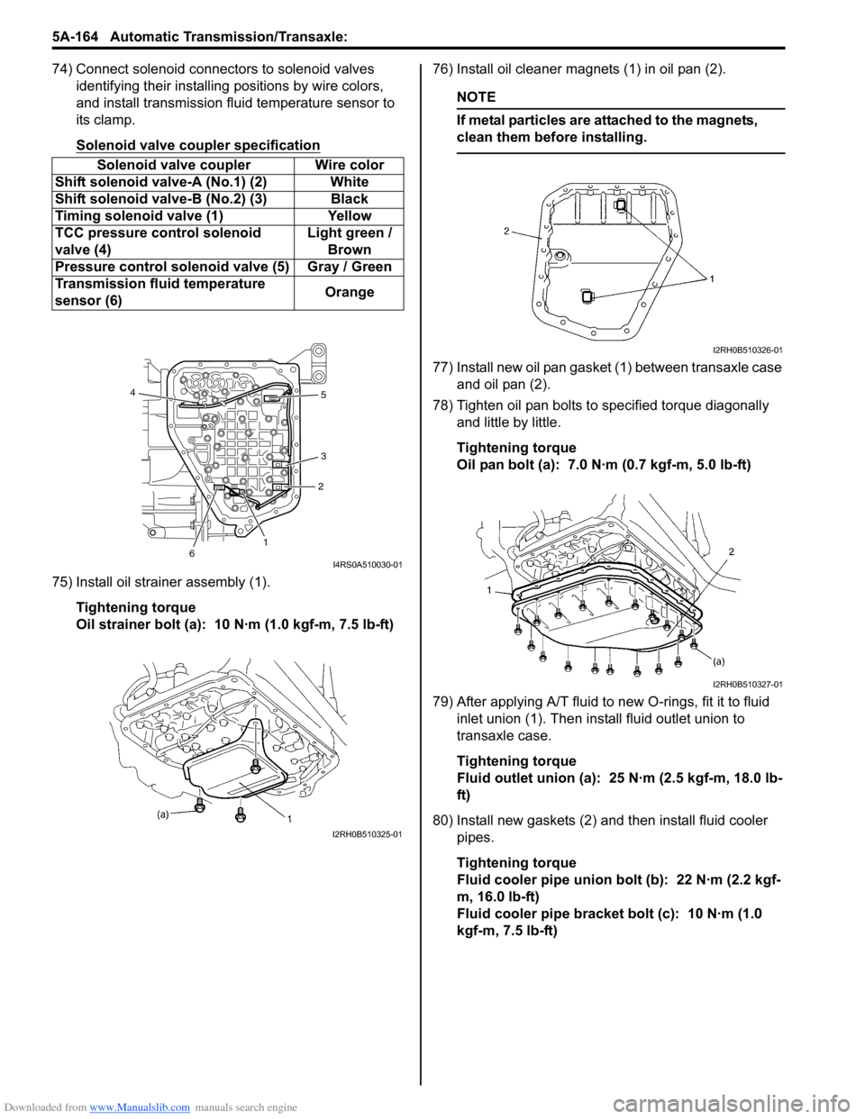
74) Connect solenoid connectors to solenoid valves identifying their installing positions by wire colors,
and install transmission fluid temperature sensor to
its clamp.
Solenoid valve coupler specification
75) Install oil strainer assembly (1).
Tightening torque
Oil strainer bolt (a): 10 N·m (1.0 kgf-m, 7.5 lb-ft) 76) Install oil cleaner magnets (1) in oil pan (2).
NOTE
If metal particles are attached to the magnets,
clean them before installing.
77) Install new oil pan gasket (1) between transaxle case
and oil pan (2).
78) Tighten oil pan bolts to specified torque diagonally and little by little.
Tightening torque
Oil pan bolt (a): 7.0 N·m (0.7 kgf-m, 5.0 lb-ft)
79) After applying A/T fluid to new O-rings, fit it to fluid inlet union (1). Then inst all fluid outlet union to
transaxle case.
Tightening torque
Fluid outlet union (a): 25 N·m (2.5 kgf-m, 18.0 lb-
ft)
80) Install new gaskets (2) and then install fluid cooler pipes.
Tightening torque
Fluid cooler pipe union bolt (b): 22 N·m (2.2 kgf-
m, 16.0 lb-ft)
Fluid cooler pipe bracket bolt (c): 10 N·m (1.0
kgf-m, 7.5 lb-ft)
Solenoid valve coupler Wire color
Shift solenoid valve-A (No.1) (2) White
Shift solenoid val ve-B (No.2) (3) Black
Timing solenoid valve (1) Yellow
TCC pressure control solenoid
valve (4) Light green /
Brown
Pressure control solenoid valve (5) Gray / Green
Transmission fluid temperature
sensor (6) Orange
12
3 5
4
6
I4RS0A510030-01
I2RH0B510325-01
I2RH0B510326-01
I2RH0B510327-01
Page 809 of 1496
Downloaded from www.Manualslib.com manuals search engine Automatic Transmission/Transaxle: 5A-165
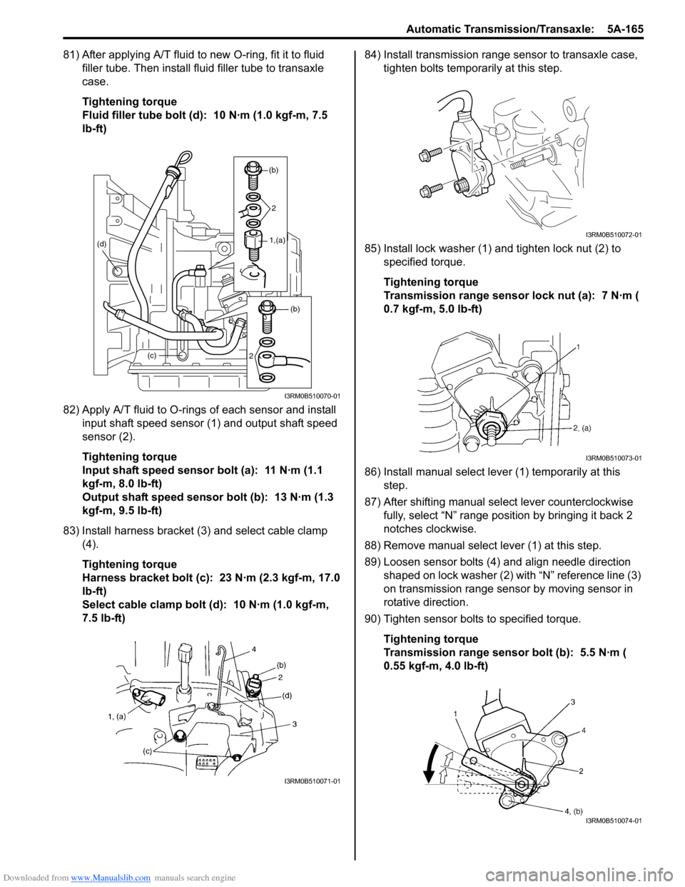
81) After applying A/T fluid to new O-ring, fit it to fluid filler tube. Then install fl uid filler tube to transaxle
case.
Tightening torque
Fluid filler tube bolt (d): 10 N·m (1.0 kgf-m, 7.5
lb-ft)
82) Apply A/T fluid to O-rings of each sensor and install input shaft speed sensor (1) and output shaft speed
sensor (2).
Tightening torque
Input shaft speed sensor bolt (a): 11 N·m (1.1
kgf-m, 8.0 lb-ft)
Output shaft speed sensor bolt (b): 13 N·m (1.3
kgf-m, 9.5 lb-ft)
83) Install harness bracket (3) and select cable clamp (4).
Tightening torque
Harness bracket bolt (c): 23 N·m (2.3 kgf-m, 17.0
lb-ft)
Select cable clamp bolt (d): 10 N·m (1.0 kgf-m,
7.5 lb-ft) 84) Install transmission range sensor to transaxle case,
tighten bolts temporarily at this step.
85) Install lock washer (1) and tighten lock nut (2) to specified torque.
Tightening torque
Transmission range sensor lock nut (a): 7 N·m (
0.7 kgf-m, 5.0 lb-ft)
86) Install manual select leve r (1) temporarily at this
step.
87) After shifting manual se lect lever counterclockwise
fully, select “N” range position by bringing it back 2
notches clockwise.
88) Remove manual select lever (1) at this step.
89) Loosen sensor bolts (4) and align needle direction shaped on lock washer (2) with “N” reference line (3)
on transmission range sensor by moving sensor in
rotative direction.
90) Tighten sensor bolts to specified torque.
Tightening torque
Transmission range sensor bolt (b): 5.5 N·m (
0.55 kgf-m, 4.0 lb-ft)
(c)
(d)
(b)
2
1,(a)
(b)
2
I3RM0B510070-01
I3RM0B510071-01
I3RM0B510072-01
I3RM0B510073-01
I3RM0B510074-01